Table of Contents
Advertisement
Quick Links
MP145E
Q-521 Miniature Stage
User Manual
Version: 1.0.0
PI miCos GmbH, Freiburger Strasse 30, 79427 Eschbach, Germany
Phone +49 7634 5057-0, Fax +49 7634 5057-99, Email info@pimicos.ws, www.pi.ws
Date: 17.03.2016
This document describes the following products:
Q-521
Q-Motion miniature linear positioning stage,
piezoelectric inertia drive
This document applies to various model
versions of the Q-521. The model version of the
Q-521 is coded in the order number by means
of three characters after a period. Meaning of
the characters and valid values:
First character after the period:
Travel range
1 = 12 mm
2 = 22 mm
3 = 32 mm
Second character after the period:
Sensor equipment
0 = without sensor
3 = with sensor, sensor resolution 4 nm
4 = with sensor, sensor resolution 1 nm
Third character after the period:
Vacuum suitability
-6
0 = suitable to 10
hPa
-9
U = suitable to 10
hPa
Advertisement
Table of Contents

Related Manuals for PI Q-521 Series


Summary of Contents for PI Q-521 Series
- Page 1 4 = with sensor, sensor resolution 1 nm Third character after the period: Vacuum suitability 0 = suitable to 10 U = suitable to 10 PI miCos GmbH, Freiburger Strasse 30, 79427 Eschbach, Germany Phone +49 7634 5057-0, Fax +49 7634 5057-99, Email info@pimicos.ws, www.pi.ws...
- Page 2 PI®, PIC®, PICMA®, PILine®, PIFOC®, PiezoWalk®, NEXACT®, NEXLINE®, NanoCube®, NanoAutomation®, Picoactuator®, PInano®, PIMag® © 2016 Physik Instrumente (PI) GmbH & Co. KG, Karlsruhe, Germany. The text, photographs and drawings in this manual are protected by copyright. With regard thereto, Physik Instrumente (PI) GmbH & Co. KG retains all the rights.
-
Page 3: Table Of Contents
Contents About this Document Objective and Target Audience of this User Manual..........1 Symbols and Typographic Conventions..............1 Definition ........................2 Figures ........................2 Other Applicable Documents ..................3 Downloading Manuals ....................3 Safety Intended Use ......................5 General Safety Instructions ..................5 Organizational Measures .................... - Page 4 5.5.1 Connecting the Q-521 to the Drive Electronics ........... 38 5.5.2 Connecting the Q-521 to the Controller ............41 Start-Up and Operation General Notes on Start-Up and Operation ............... 47 Starting Up the stage ....................50 6.2.1 Starting Up the Q-521.x0x with Drive Electronics ........51 6.2.2 Starting Up the Q-521.x3x or Q-521.x4x with a Controller ......
- Page 5 Old Equipment Disposal EC Declaration of Conformity...
-
Page 7: About This Document
1 About this Document About this Document In this Chapter Objective and Target Audience of this User Manual ..............1 Symbols and Typographic Conventions ..................1 Definition ............................2 Figures ............................2 Other Applicable Documents ......................3 Downloading Manuals ........................3 Objective and Target Audience of this User Manual This manual contains the necessary information on the intended use of the Q-521. -
Page 8: Definition
1 About this Document INFORMATION Information for easier handling, tricks, tips, etc. Symbol/ Meaning Label Action consisting of several steps whose sequential order must be observed Action consisting of one or several steps whose sequential order is irrelevant List item p. -
Page 9: Other Applicable Documents
1 About this Document Other Applicable Documents The devices and software tools which are mentioned in this documentation are described in their own manuals. Description Document E-870.10, E-870.11, E-870.21, E-870.41 Piezomotor / E870T0001 Technical Note PiezoMike Drive Electronics, OEM Board, 1 to 4 Channels E-870.1G, E-870.2G, E-870.4G Piezomotor / PiezoMike E870T0002 Technical Note Drive Electronics, Bench-Top, 1 to 4 Channels... - Page 10 1 About this Document Downloading Manuals 1. Open the website http://www.pi.ws. 2. Click Info. 3. If you have a user name and password: a) Click Login. b) Log in with the user name and password. 4. Click >> Product Downloads.
-
Page 11: Safety
2 Safety Safety In this Chapter Intended Use ..........................5 General Safety Instructions......................5 Organizational Measures ....................... 6 Measures for Handling Vacuum-Compatible Products ..............6 Intended Use The Q-521 is a laboratory device as defined by DIN EN 61010-1. It is intended to be used in interior spaces and in an environment which is free of dirt, oil, and lubricants. -
Page 12: Organizational Measures
When handling the vacuum version of the stage, attention must be paid to appropriate cleanliness. At PI, all parts are cleaned before assembly. During assembly and measurement, powder-free gloves are worn. In addition, the Q-521.xxU models are wipe cleaned afterwards and then shrink-wrapped twice in vacuum-compatible film. -
Page 13: Product Description
3 Product Description Product Description In this Chapter Model Overview ..........................7 Product View ..........................10 Product Labeling .......................... 12 Scope of Delivery ......................... 13 Accessories ........................... 14 Suitable Electronics ........................15 Technical Features ........................17 Model Overview Classification of the Q-521 models The model version of the Q-521 is coded in the order number by means of three characters after a period;... - Page 14 3 Product Description Order number Product name Q-521.10U Q-Motion® Miniature Linear Positioning Stage, 12 mm Travel Range, Without Position Sensor for Open-Loop Operation, 1 N Push/Pull Force, Dimensions 21 × 30 × 10 mm (W × L × H), Piezoelectric Inertia Drive, Vacuum-Compatible to 10 Q-521.130 Q-Motion®...
- Page 15 3 Product Description Order number Product name Q-521.30U Q-Motion® Miniature Linear Positioning Stage, 32 mm Travel Range, Without Position Sensor for Open-Loop Operation, 1 N Push/Pull Force, Dimensions 21 × 42 × 10 mm (W × L × H), Piezoelectric Inertia Drive, Vacuum-Compatible to 10 Q-521.330 Q-Motion®...
-
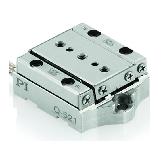
Page 16: Product View
3 Product Description Product View Figure 1: Example for models without sensor: Q-521.200 stage Moving platform Cable exit for drive connection Connection for drive; with Q-521.x00 models: Sub-D 15 (m) connector, with Q-521.x0U models: Sub-D 15 (f) connector Type plate p. 12 Base body Version: 1.0.0 MP145E... - Page 17 3 Product Description Figure 2: Example for models with sensor: Q-521.240 stage Moving platform Cable exit for connection of drive and sensor Warning sign "Electrostatic sensitive devices" Connection for drive and sensor; with Q-521.xx0 models: Sub-D 15 (m) connector, with Q-521.xxU models: Sub-D 15 (f) connector ESD protection: ESD protective cap with Q-521.xx0;...
-
Page 18: Product Labeling
3 Product Description Figure 3: Direction of motion of the platform of the Q-521, Q-521.240 used as an example The arrow in the figure above shows the direction of motion on positive commanding. Product Labeling Figure 4: Example for models with sensor: Product labeling and type plate of the Q-521.240 stage Version: 1.0.0 MP145E Q-521 Miniature Stage... -
Page 19: Scope Of Delivery
4 to 9 = consecutive numbers Product name (example), the characters Q-521.240 following the period refer to the model Old equipment disposal WWW.PI.WS Manufacturer's address (website) Warning sign "Electrostatic sensitive devices" Scope of Delivery The Q-521 is delivered with the following components:... -
Page 20: Accessories
3 Product Description Item ID Components Only for models with sensor: Air-side adapter cable for connection to the E-871 controller, 7202500043-0015 Sub-D 15 (f) to HD Sub-D 15 (m) and HD Sub-D 15 (f), 0.3 m Only for models suitable for operation to 10 hPa: 5604500041 Adapter for operation outside of a vacuum chamber, Sub-D 15 (m/m) -
Page 21: Suitable Electronics
3 Product Description For Q-521.xx0 models only (suitable for use in a vacuum to 10 hPa): Order number Description Vacuum feedthrough (drive and sensor signals), Sub-D 15 (m/f), including C-815.VF C815T0003 Technical Note For Q-521.xxU models only (suitable for use in a vacuum to 10 hPa): Order number Description... - Page 22 3 Product Description Electronics Suitable for Order number Description Stage without Stage with sensor sensor Q-521.x3x Q-521.x0x Q-521.x4x E-870.21 PIShift Piezomotor / PiezoMike Drive Electronics, 2 Channels, OEM Board with Connector Strip E-870.2G PIShift Piezomotor / PiezoMike Drive Electronics, 2 Channels, ...
-
Page 23: Technical Features
Settings for the sensor: Interpolation rate, corrections of hysteresis as well as of phase and offset, gain values When switched on or rebooted, controllers from PI read the data from the ID chip. For more information on the ID chip recognition, see the manual of the controller used. Q-521 Miniature Stage MP145E Version: 1.0.0... -
Page 25: Unpacking
When handling the vacuum version of the stage, attention must be paid to appropriate cleanliness. At PI, all parts are cleaned before assembly. During assembly and measurement, powder-free gloves are worn. In addition, the Q-521.xxU models are wipe cleaned afterwards and then shrink-wrapped twice in vacuum-compatible film. -
Page 27: Installation
5 Installation Installation In this Chapter General Notes on Installation ...................... 21 Mounting the Q-521 on a Surface and Connecting It to a Protective Earth Conductor ....23 Setting Up a Multi-Axis System ....................25 Affixing the Load to the Q-521 ..................... 36 Connecting the Q-521 to the Electronics .................. - Page 28 When the stage is mounted vertically, make sure that the installed load is lower than the self-locking of the drive (p. 61). NOTICE Damage from unsuitable cables! Unsuitable cables can damage the electronics. Only use cables provided by PI for connecting the Q-521 to the electronics. Version: 1.0.0 MP145E Q-521 Miniature Stage...
-
Page 29: Mounting The Q-521 On A Surface And Connecting It To A Protective Earth Conductor
5 Installation INFORMATION For optimum repeatability, all components must be firmly affixed to each other. INFORMATION When handling the vacuum version of the stage, appropriate cleanliness must be ensured. Only touch the stage with powder-free gloves. If necessary, wipe the stage clean. INFORMATION The positive direction of motion of the axis is given in the product view (p. - Page 30 5 Installation INFORMATION The electrical contact of the Q-521 to the protective earth conductor is established via the surface, on which the Q-521 is mounted. The corresponding contact surfaces must be sufficiently conductive. The protective earth conductor is connected to the surface on which the Q-521 is mounted.
-
Page 31: Setting Up A Multi-Axis System
5 Installation Option: 2 1.5 m6 x 4 locating pins, in the scope of delivery Suitable tools for tightening the screws Thread-locking adhesive Mounting the Q-521 on a surface and connecting it to a protective earth conductor Figure 6: Mounting from above, using a Q-521.2xx as an example Option: Aligning the stage (view from below) on the surface with 1.5 m6 x 4 locating pins. - Page 32 5 Installation Figure 7: Example of an XYZ system: Three Q-521.240 mounted using an adapter plate and an adapter bracket Lower stage Q-121.80U adapter plate (for use in a vacuum to 10 hPa) Middle stage Q-121.x0U adapter bracket (for use in a vacuum to 10 hPa) Upper stage Version: 1.0.0...
-
Page 33: General Information On Setting Up A Multi-Axis System
5 Installation 5.3.1 General Information on Setting Up a Multi-Axis System NOTICE Impermissibly high load on the stages! In a multi-axis system, the stage used for the Y and/or Z axis must also be moved. Impermissibly high loads impair the motion and can damage the stages. ... - Page 34 5 Installation Requirements You have read and understood the general notes on installation (p. 21). You have read and understood the general notes on setting up a multi-axis system (p. 27). The stages are disconnected from the electronics. ...
- Page 35 5 Installation Setting up an XY system Figure 8: Example: Mounting a Q-521.240 on a Q-521.240 Lower stage 2 locating pins, 1.5 m6 x 4 Q-121.80U adapter plate 2 machine screws, M2x4 2 locating pins, 1.5 m6 x 4 2 socket head cap screws, M2x6 Upper stage 1.
-
Page 36: Setting Up A Z System With An Adapter Bracket
5 Installation − Maximum torque: 35 Ncm 3. Check that the upper stage is affixed firmly. 5.3.3 Setting Up a Z System with an Adapter Bracket NOTICE Screws and locating pins that are too long! Screws and locating pins that are inserted too deeply damage the Q-521. ... - Page 37 5 Installation Systems with Q-121.10U adapter bracket Orientation of adapter bracket and upper stage to the lower stage: Combination of 0° 90° 180° 270° stages and adapter bracket: Q-521.1xx + Q-121.10U Q-521.2xx + Not possible. The Not possible. The moving platforms of moving platforms of the stages collide the stages collide...
- Page 38 5 Installation Systems with Q-121.20U adapter bracket Orientation of adapter bracket and upper stage to the lower stage: Combination of 0° 90° 180° 270° stages and adapter bracket: Q-521.2xx + Q-121.20U Q-521.3xx + Not possible. The Not possible. The moving platforms of moving platforms of the stages collide the stages collide...
- Page 39 5 Installation Systems with Q-121.30U adapter bracket Orientation of adapter bracket and upper stage to the lower stage: Combination of 0° 90° 180° 270° stages and adapter bracket: Q-521.3xx + Q-121.30U Requirements You have read and understood the general notes on installation (p. 21). ...
- Page 40 5 Installation − Q-121.10U adapter bracket − Q-121.20U adapter bracket − Q-121.30U adapter bracket For the diameter and position of the holes in the adapter bracket, see "Dimensions" (p. 65) Mounting accessories from the scope of delivery of the adapter bracket: ...
- Page 41 5 Installation Setting up a Z system with an adapter bracket Figure 9: Example: Setting up an XZ system consisting of two Q-521.240 and a Q-121.20U adapter bracket Lower stage 4 locating pins, 1.5 m6 x 5 Q-121.20U adapter bracket 6 machine screws, M2x8 Upper stage 1.
-
Page 42: Affixing The Load To The Q-521
5 Installation 3. Check that the adapter bracket and the upper stage are affixed firmly. Affixing the Load to the Q-521 NOTICE Impermissibly high forces and torques! Impermissibly high forces and torques that are applied to the moving platform can damage the Q-521. - Page 43 5 Installation Q-521.1xx Q-521.2xx Q-521.3xx The arrows mark the mounting holes in the moving platform of the Q-521: For aligning the load: White arrows: Locating holes Ø 1.5 mm H7, depth 3 mm For affixing the load: Black arrows: M2 threaded holes, depth 3 mm Requirements ...
-
Page 44: Connecting The Q-521 To The Electronics
5 Installation Affixing the load to the Q-521 1. Option: Align the load on the Q-521 with the locating pins. 2. Affix the load using the screws. − Maximum torque: 35 Ncm 3. Check that load is affixed firmly. Connecting the Q-521 to the Electronics The electronics to be used for operating the Q-521 depends on the presence of a sensor (see also "Suitable Electronics"... - Page 45 5 Installation If a Q-521.x0U is to be operated at atmospheric pressure: 5604500041 adapter, in the scope of delivery (p. 13) If the Q-521 is to be operated in a vacuum: − E-873.UHVx extension cable, available as optional accessory (p. 14) −...
- Page 46 5 Installation 1. Connect the stage and drive electronics to each other as shown in the connection diagram above. 2. Take suitable measures to secure the connections against accidental disconnection. Connecting the Q-521.x0x to E-870 drive electronics with Mini-DIN 4 socket for operation in a vacuum Figure 12: Connection diagram for Q-521.x00 and drive electronics with Mini-DIN 4 socket,...
-
Page 47: Connecting The Q-521 To The Controller
5 Installation a) Obtain the dimensions from the corresponding dimensional drawing (p. 72). b) Make sure that the vacuum feedthrough is oriented correctly: C-815.VF: Vacuum side = Sub-D 15 (f) socket C-815.VFUx: See dimensional drawing (p. 72) c) Make a suitable opening in the vacuum chamber. d) Install the vacuum feedthrough. - Page 48 5 Installation − Suitable tools for installing the vacuum feedthrough Connecting the Q-521.x3x or Q-521.x4x to the E-871 controller for operation at atmospheric pressure Figure 14: Connection diagram for Q-521.x30 or Q-521.x40 and E-871 controller, for operation at atmospheric pressure E-871.1A1 controller 7202500043-0015 Y adapter cable Q-521.x30 or Q-521.x40...
- Page 49 5 Installation Connecting the Q-521.x3x or Q-521.x4x to the E-873 controller for operation at atmospheric pressure Figure 16: Connection diagram for Q-521.x30 or Q-521.x40 and E-873 controller, for operation at atmospheric pressure E-873 controller (here E-873.1A1) Q-521.x30 or Q-521.x40 Figure 17: Connection diagram for Q-521.x4U and E-873 controller, for operation at atmospheric pressure E-873 controller (here E-873.1A1)
- Page 50 5 Installation Connecting the Q-521.x3x or Q-521.x4x to the E-871 controller for operation in a vacuum Figure 18: Connection diagram for Q-521.x30 or Q-521.x40 and E-871 controller, for operation in a vacuum to 10 E-871.1A1 controller 7202500043-0015 Y adapter cable E-873.UHVx extension cable C-815.VF vacuum feedthrough Q-521.x30 or Q-521.x40...
- Page 51 5 Installation d) Install the vacuum feedthrough. 2. Remove the ESD protection from the connection of the Q-521. 3. Connect the stage and controller to each other as shown in the connection diagram above. 4. Secure the connections with the integrated screws against accidental disconnection. Connecting the Q-521.x3x or Q-521.x4x to the E-873 controller for operation in a vacuum Figure 20:...
- Page 52 5 Installation 1. Before connecting for the first time: Install the vacuum feedthrough: a) Obtain the dimensions from the corresponding dimensional drawing (p. 72). b) Make sure the vacuum feedthrough is oriented correctly: C-815.VF: Vacuum side = Sub-D 15 (f) socket C-815.VFUx: See dimensional drawing (p.
-
Page 53: Start-Up And Operation
6 Start-Up and Operation Start-Up and Operation In this Chapter General Notes on Start-Up and Operation .................. 47 Starting Up the stage ........................50 General Notes on Start-Up and Operation CAUTION Risk of electric shock if the protective earth conductor is not connected! If a protective earth conductor is not or not properly connected, dangerous touch voltages can occur on the Q-521 in the case of malfunction or failure of the system. - Page 54 An operating frequency that is too high can cause damage to the Q-521. Only operate the Q-521 with controllers/drivers and original accessories from PI. Do not exceed the operating frequency range (p. 63) for which the Q-521 is specified.
- Page 55 Operating voltages that are too high or incorrectly connected can cause damage to the Q-521. Only operate the Q-521 with controllers/drivers and original accessories from PI. Do not exceed the operating voltage range (p. 63) for which the Q-521 is specified.
-
Page 56: Starting Up The Stage
6 Start-Up and Operation NOTICE Destruction of the piezo actuators by electric flashovers! Using the Q-521 in environments that increase the electrical conductivity can lead to the destruction of the piezo actuators of the drive by electric flashovers. Electric flashovers can be caused by moisture, high humidity, liquids and conductive materials (e.g. -
Page 57: Starting Up The Q-521.X0X With Drive Electronics
6 Start-Up and Operation 6.2.1 Starting Up the Q-521.x0x with Drive Electronics INFORMATION The values for the parameters of the E-870 drive electronics are listed in a table in this section. For optimum drive performance, the values of the following parameters should be identical: ... -
Page 58: Starting Up The Q-521.X3X Or Q-521.X4X With A Controller
PIMicosStages2.dat stage database. The entries in the stage database are updated regularly. Download the PI Update Finder from the PI website (http://www.update.pi-portal.ws) and use it to update the PIMicosStages2.dat stage database on your PC. - Page 59 6 Start-Up and Operation The controller and the required PC software have been installed. All connections on the controller have been set up (see user manual of the controller). Starting up the Q-521.x3x or Q-521.x4x with the E-871 or E-873 controller 1.
-
Page 61: Maintenance
7 Maintenance Maintenance In this Chapter General Notes on Maintenance ....................55 Performing a Maintenance Run ....................55 Cleaning the Q-521 ........................55 General Notes on Maintenance NOTICE Damage due to improper maintenance! Improper maintenance can lead to misalignment and failure of the Q-521. ... -
Page 63: Troubleshooting
Drive Electronics" (p. 51) and Technical Note The stage has E870T0001 and/or E870T0002). been replaced E-871 or E-873 controller from PI: Load the parameter set from the stage database that corresponds to the Q-521 model. If necessary: Set the parameters on the... - Page 64 8 Troubleshooting Problem Possible causes Solution Unfavorable load Observe the maximum torque when affixing mounting the load (p. 36). Keep the distance between the center of gravity of the load and the center of the moving platform as small as possible in all directions.
-
Page 65: Customer Service
9 Customer Service Customer Service For inquiries and orders, contact your PI sales engineer or send us an e-mail (info@pi.ws). If you have questions concerning your system, have the following information ready: − Product codes and serial numbers of all products in the system −... -
Page 67: Technical Data
10 Technical Data Technical Data In this Chapter Specifications ..........................61 Operating Time ..........................64 Dimensions ..........................65 Pin Assignment ..........................78 10.1 Specifications 10.1.1 Data Table Preliminary Data Q-521.130 Q-521.140 Q-521.230 Q-521.240 Q-521.330 Q-521.340 Q-521.x00 Unit Q-521.14U Q-521.24U Q-521.34U Q-521.x0U Motion and 12 mm... - Page 68 10 Technical Data Preliminary Data Q-521.130 Q-521.140 Q-521.230 Q-521.240 Q-521.330 Q-521.340 Q-521.x00 Unit Q-521.14U Q-521.24U Q-521.34U Q-521.x0U Bidirectional repeatability over entire travel range Unidirectional repeatability over 100 µm travel range Bidirectional repeatability over 100 µm travel range Pitch / yaw over µrad entire travel range...
-
Page 69: Maximum Ratings
10 Technical Data Preliminary Data Q-521.130 Q-521.140 Q-521.230 Q-521.240 Q-521.330 Q-521.340 Q-521.x00 Unit Q-521.14U Q-521.24U Q-521.34U Q-521.x0U Cable length Connector Sub-D Sub-D Sub-D Sub-D Sub-D Sub-D Sub-D Recommended E-871, E-871, E-871, E-871, E-871, E-871, E-870 controller E-873 E-873 E-873 E-873 E-873 E-873 * Typical velocity at a control frequency of 20 kHz... -
Page 70: Operating Time
10 Technical Data Storage temperature -20 °C to 70 °C Transport temperature -20 °C to 70 °C Maximum bakeout temperature 120 °C, for 12 hours, only in switched-off state for Q-521.xxU: Maximum bakeout temperature 80 °C, for 2 hours, only in switched-off state for Q-521.xx0: Overvoltage category (acc. -
Page 71: Dimensions
10 Technical Data 10.3 Dimensions 10.3.1 Q-521.1xx Dimensions in mm. Note that the decimal places are separated by a comma in the drawings. Figure 22: Q-521.1xx Q-521 Miniature Stage MP145E Version: 1.0.0... -
Page 72: Q-521.2Xx
10 Technical Data 10.3.2 Q-521.2xx Dimensions in mm. Note that the decimal places are separated by a comma in the drawings. Figure 23: Q-521.2xx Version: 1.0.0 MP145E Q-521 Miniature Stage... -
Page 73: Q-521.3Xx
10 Technical Data 10.3.3 Q-521.3xx Dimensions in mm. Note that the decimal places are separated by a comma in the drawings. Figure 24: Q-521.3xx Q-521 Miniature Stage MP145E Version: 1.0.0... -
Page 74: Q-121.80U Adapter Plate
10 Technical Data 10.3.4 Q-121.80U Adapter Plate Dimensions in mm. Note that the decimal places are separated by a comma in the drawings. Figure 25: Q-121.80U adapter plate Version: 1.0.0 MP145E Q-521 Miniature Stage... -
Page 75: Q-121.10U Adapter Bracket
10 Technical Data 10.3.5 Q-121.10U Adapter Bracket Dimensions in mm. Note that the decimal places are separated by a comma in the drawings. Figure 26: Q-121.10U adapter bracket Q-521 Miniature Stage MP145E Version: 1.0.0... -
Page 76: Q-121.20U Adapter Bracket
10 Technical Data 10.3.6 Q-121.20U Adapter Bracket Dimensions in mm. Note that the decimal places are separated by a comma in the drawings. Figure 27: Q-121.20U adapter bracket Version: 1.0.0 MP145E Q-521 Miniature Stage... -
Page 77: Q-121.30U Adapter Bracket
10 Technical Data 10.3.7 Q-121.30U Adapter Bracket Dimensions in mm. Note that the decimal places are separated by a comma in the drawings. Figure 28: Q-121.30U adapter bracket Q-521 Miniature Stage MP145E Version: 1.0.0... -
Page 78: Vacuum Feedthroughs
10 Technical Data 10.3.8 Vacuum Feedthroughs Available vacuum feedthroughs: C-815.VF (p. 73) C-815.VFU1 (p. 74) C-815.VFU3 (p. 75) C-815.VFU6 (p. 76) C-815.VFU15 (p. 77) Version: 1.0.0 MP145E Q-521 Miniature Stage... - Page 79 10 Technical Data C-815.VF vacuum feedthrough for 10 Dimensions in mm. Note that the decimal places are separated by a comma in the drawings. Figure 29: C-815.VF vacuum feedthrough Sub-D 15 (m/f) Q-521 Miniature Stage MP145E Version: 1.0.0...
- Page 80 10 Technical Data C-815.VFU1 vacuum feedthrough for 10 Dimensions in mm. Note that the decimal places are separated by a comma in the drawings. Figure 30: C-815.VFU1 vacuum feedthrough, Sub-D 15 (m/m) Vacuum side Air side Version: 1.0.0 MP145E Q-521 Miniature Stage...
- Page 81 10 Technical Data C-815.VFU3 vacuum feedthrough for 10 Dimensions in mm. Note that the decimal places are separated by a comma in the drawings. Figure 31: C-815.VFU3 vacuum feedthrough, Sub-D 15 (m/m) Vacuum side Air side Q-521 Miniature Stage MP145E Version: 1.0.0...
- Page 82 10 Technical Data C-815.VFU6 vacuum feedthrough for 10 Dimensions in mm. Note that the decimal places are separated by a comma in the drawings. Figure 32: C-815.VFU6 vacuum feedthrough, Sub-D 15 (m/m) Vacuum side Air side Version: 1.0.0 MP145E Q-521 Miniature Stage...
- Page 83 10 Technical Data C-815.VFU15 vacuum feedthrough for 10 Dimensions in mm. Note that the decimal places are separated by a comma in the drawings. Figure 33: C-815.VFU15 vacuum feedthrough, Sub-D 15 (m/m) Vacuum side Air side Q-521 Miniature Stage MP145E Version: 1.0.0...
-
Page 84: Pin Assignment
10 Technical Data 10.4 Pin Assignment 10.4.1 Q-521.xx0 Connector: Sub-D 15 (m) The Sub-D 15 (m) connector transmits the signals of the drive and, for the models with sensor, in addition the signals of the sensor and of the ID chip. Figure 34: Sub-D 15 (m) connector Signal... -
Page 85: Q-521.Xxu
10 Technical Data The "-" sign indicates that the corresponding pin has not been assigned. Only for models with sensor. Not assigned for models without sensor. The cable shield is connected to the connector shell. 10.4.2 Q-521.xxU Connector: Sub-D 15 (f) The Sub-D 15 (f) connector transmits the signals of the drive and, for the models with sensor, in addition the signals of the sensor and of the ID chip. -
Page 86: C-815.Vf Vacuum Feedthrough
10 Technical Data Signal Function Direction Motor (+) Motor signal differential (+) Input Motor (-) Motor signal differential (-) Input The "-" sign indicates that the corresponding pin has not been assigned. Only for models with sensor. Not assigned for models without sensor. The cable shield is connected to the connector shell. -
Page 87: C-815.Vfux Vacuum Feedthrough
10 Technical Data Vacuum side (f) Air side (m) Signal Function REF - Reference signal differential (-) Motor (-) Motor signal differential (-) Motor (+) Motor signal differential (+) Supply voltage (+5 V) ID chip data ID chip data SIN - Encoder A (-) COS - Encoder B (-) - Page 88 10 Technical Data Figure 39: Sub-D 15 (m) panel plug Vacuum side Air side Signal Function COS - Encoder B (-) SIN - Encoder A (-) ID chip data ID chip data Supply voltage (+5 V) Motor (+) Motor signal differential (+) Motor (-) Motor signal differential (-) REF -...
-
Page 89: 5604500041 Adapter
10 Technical Data 10.4.5 5604500041 Adapter Sub-D 15 (m/m) The adapter is only required if a Q-521.xxU model is to be operated at atmospheric pressure (i.e., without a vacuum feedthrough). Figure 40: Sub-D 15 (m) connector Figure 41: Pin assignment of the 5604500041 adapter Q-521 Miniature Stage MP145E Version: 1.0.0... - Page 91 PI miCos equipment made available on the market after 13 August 2005 without charge. Any old PI miCos equipment can be sent free of charge to the following address: PI miCos GmbH Freiburger Strasse 30...
- Page 93 12 EC Declaration of Conformity EC Declaration of Conformity For the Q-521, an EC Declaration of Conformity has been issued in accordance with the following European directives: Low Voltage Directive EMC Directive RoHS Directive The applied standards certifying the conformity are listed below. Safety (Low Voltage Directive): EN 61010-1 EMC: EN 61326-1 RoHS: EN 50581...
Need help?
Do you have a question about the Q-521 Series and is the answer not in the manual?
Questions and answers