Table of Contents
Advertisement
Quick Links
INSTALLER AND OWNER GUIDE
Please keep me in a safe place for future use.
Models;
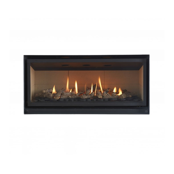
1000FS, 1000RC
Inset live fuel effect gas fire
We trust that this guide gives sufficient details to enable this appliance to be installed,
operated and maintained satisfactorily. However, if further information is required, our
Valor Technical Helpline will be pleased to help.
Telephone 0844 879 35 88 (National call rates apply in the United Kingdom).
In the Republic of Ireland Telephone 01 842 8222.
©
GDC Group Ltd. NOV 2017
600FS, 600RC
800FS, 800RC
08/53230/0 REV: 06
Advertisement
Table of Contents

Related Manuals for Valor Inspire 1000FS


Summary of Contents for Valor Inspire 1000FS
- Page 1 We trust that this guide gives sufficient details to enable this appliance to be installed, operated and maintained satisfactorily. However, if further information is required, our Valor Technical Helpline will be pleased to help. Telephone 0844 879 35 88 (National call rates apply in the United Kingdom).
- Page 2 THIS APPLIANCE IS FOR USE WITH NATURAL GAS (G20). THIS APPLIANCE IS SUITABLE ONLY FOR INSTALLATION IN THE UNITED KINGDOM (GB) AND THE REPUBLIC OF IRELAND (IE). © GDC Group Ltd. All rights reserved. No part of this publication may be reproduced in any material form (including photocopying), stored in any medium by electronic means (including in any retrieval system or database) or transmitted, in any form or by any means, whether electronic, mechanical, recording or otherwise, without the prior written permission of...
- Page 3 BS EN ISO 9001 quality system accepted by the British Standards Institute. The Highest Standards Valor is a member of the Benchark scheme and HHIC (Heating and Hot water Industry Council) that work to ensure high standards of safety, quality and performance.
-
Page 4: Installer Guide
INSTALLER GUIDE INSTALLER GUIDE FOR OWNER GUIDE SEE PAGES 45 TO 64 © Page 4 GDC Group Ltd. NOV 2017... -
Page 5: Table Of Contents
INSTALLER GUIDE CONTENTS Section Page INSTALLER GUIDE 4 - 44 OWNER GUIDE 45 - 64 1. APPLIANCE DIMENSIONS 2. SAFETY 3. THE BENCHMARKING SCHEME 4. APPLIANCE DATA, EFFICIENCY AND NOx 4.1 General information. 4.2 Efficiency. 4.3 NOx 4.4 Accessories 5. GENERAL INSTALLATION REQUIREMENTS 5.1 Regulations, Standards and Law. - Page 6 CONTENTS (Continued) Section Page 11. CONVECTION BOX INSTALLATION 11.1 Method 1 - Front fixing to fireplace surround. 11.2 Method 2 - Cable retention and floor fixing. 26 - 27 11.3 Sealing floor front - Method 1 & 2 inc Frameless 12.
- Page 7 INSTALLER GUIDE CONTENTS (Continued) Section Page 18. SERVICING & PARTS REPLACEMENT 18.1 To remove the trim. 18.2 To remove the visual baffle. 18.3 To remove the window door panel. 18.4 To remove the fuel effect and ember wool 18.5 To remove the top tray. 18.6 To remove the base tray.
-
Page 8: Appliance Dimensions
INSTALLER GUIDE 1.APPLIANCE DIMENSIONS Dimension 600FS / 600RC 800FS / 800RC 1000FS / 1000RC 470 mm 470 mm 470 mm 646 mm 846 mm 968 mm 293 mm 293 mm 293 mm 596 mm 796 mm 918 mm 443 mm 443 mm 443 mm FRAMELESS... -
Page 9: Safety
INSTALLER GUIDE 2.SAFETY Installer Before continuing any further with the installation of this appliance please read the following guide to manual handling. The lifting weight of this appliance (kg) is approx as below: Model Weight 600RCInspire engine only* 18.0 Kg 600FS Inspire engine only* 17.5 Kg 800RCInspire engine only*... -
Page 10: The Benchmarking Scheme
INSTALLER GUIDE 3.THE BENCHMARK SCHEME GDC Group is a licensed member of the Benchmark Scheme which aims to improve the standards of installation and commissioning of domestic heating and hot water systems in the UK and to encourage regular servicing to optimise safety, efficiency and performance. -
Page 11: Appliance Data, Efficiency And Nox
INSTALLER GUIDE Accessories 4. APPLIANCE DATA, EFFICIENCY, NO x AND 4.1 General information. The appliance information label is located on the burner tray on the left hand side of the fire. This can be found by removing the Visual Baffle and Trim if fitted. Models 600FS/600RC 800FS/800RC... -
Page 12: Efficiency
For NG the 'Weighted' result for these appliances equates to NO x Class 4. 4.4 Accessories Gather Hood Connector Inspire 600FS/600RC Product Code: 061638 Gather Hood Connector Inspire 800FS/800RC Product Code: 061645 & Inspire 1000FS/1000RC © Page 12 GDC Group Ltd. NOV 2017... -
Page 13: General Installation Requirements
INSTALLER GUIDE 5. GENERAL INSTALLATION REQUIREMENTS 5.1 Regulations, Standards and Law. The installation must be in accordance with these instructions. For the user’s protection, in the United Kingdom it is the law that all gas appliances are installed by competent persons in accordance with the current edition of the Gas Safety (Installation and Use) Regulations. -
Page 14: The Atmosphere Sensing Device (Asd)
INSTALLER GUIDE 5.3 The Atmosphere sensing device (ASD). The appliance is fitted with an A.S.D (Atmosphere sensing device). If the appliance closes down after a period of operation for no apparent reason, the consumer should be informed to stop using the appliance until the installation and appliance have been thoroughly checked. -
Page 15: The Fireplace
INSTALLER GUIDE 5.7.4 Like all efficient gas fires care should be taken to the choice and layout of installed back panels. Marble and other similar natural materials may have microscopic flaws or stress points, under heat these may open and crack. If in doubt the use of a three/four piece back panel layout is recommended. -
Page 16: Installation Options
INSTALLER GUIDE 5.10 Installation options. In the United Kingdom, as supplied, the appliance can be installed in the following situations: Hearth & Fireplace opening dims Dimension 600FS / 600RC 800FS / 800RC 1000FS / 1000RC 460 mm Max / 450 mm Min 460 mm Max / 450 mm Min 460 mm Max / 450 mm Min 635 mm Max / 600 mm Min... -
Page 17: Flues
INSTALLER GUIDE 5.10.3. Gather hood installation in Stud work Chimney The Inspire gas fire products are intended to be used only in a fireplace of non- combustible material.However if a stud work chimney breast is used the builder/installer MUST ensure to leave a minimum 75mm clear to the sides of the appliance and a minimum of 100mm clear to the rear of the gather hood connector. - Page 18 INSTALLER GUIDE © Page 18 GDC Group Ltd. NOV 2017...
-
Page 19: Pack Contents
INSTALLER GUIDE 6. PACK CONTENTS The items required for this appliance are packed in sections. The Ceramic/Vermiculite/Glass liner options are all fragile so care necessary when handling. They are packed inside the top fitment as you open the carton. Section 1 - Fire unit contains: Burner and convection box unit. -
Page 20: Fireplace Check
INSTALLER GUIDE 7. FIREPLACE CHECK 8.1 Soundness for appliance attachment Primary method of retaining the appliance is by fixing to the fireplace front. Using concealed The methods are detailed in section 11 of this manual. Before selecting the retention method, consult with the customer. Method 2 is provided for instances where drilling holes in the front surface of the fireplace surround is unacceptable to the customer or otherwise impractical. -
Page 21: Preparing Appliance For Installation
INSTALLER GUIDE 9. PREPARING APPLIANCE FOR INSTALLATION 1. Remove the visual baffle, by unscrewing by hand the two M5 knurled screws in an anti clockwise direction. Keep these two screws save as they will be needed later. Carefully slide out the visual baffle and place carefully to one side. - Page 22 INSTALLER GUIDE 6. Detach the burner tray from the convection box by removing two locating screws. Slide the burner tray forward and clear of the convection box. IMPORTANT Before continuing with the installation of this gas fire the aeration setting on the burner must be checked.
-
Page 23: Ignition Check
INSTALLER GUIDE 9. There is a length of self adhesive foam seal supplied with the fire. This will need to be fitted to the outer rear edges of the side and top flanges of the convector box. Ensure that there is no gap between the foam seals where they meet. -
Page 24: Setting The Handset And Receiver Relationship (Rc)
INSTALLER GUIDE WARNING: NEVER connect a 9-Volt battery directly to the cable of the remote battery box. This connection is the only to be used to connect the reciever to the remote control. It is important that the wires from the battery box do not touch the underside of the burner tray and that the battery box is positioned as far on the Left Hand Side as possible and along the front to make access for replacement of batteries as easy as possible. -
Page 25: Fitting Slider Handle To Control Cam (Fs)
INSTALLER GUIDE Slider Control (FS) Models 9.5 Fitting slider handle to control cam. The slider handle needs to be fitted to the cam assembly as shown, with the two M4 x 8mm screws provided. NOTE: Two handle finish options have been supplied Chrome and Black please ask the customers preference before selecting one to be fitted. -
Page 26: Convection Box Installation
INSTALLER GUIDE 11. CONVECTION BOX INSTALLATION 11.1 Method 1 - Front fixing to fireplace surround. 1. Make sure that the fireplace front surround area is sound enough to take the wall plugs and screws. If necessary, make sound with suitable cement. 2. - Page 27 INSTALLER GUIDE Upper cable locations masonry drill for the wall plugs supplied. The holes should be equidistant each side of the centre line of the fireplace to ensure that the appliance finishes centrally in the opening when tension is applied to the cables. Lower cable retention 3.
-
Page 28: Sealing Floor Front - Method 1 & 2 Inc Frameless
INSTALLER GUIDE used, insert the convection box into the fireplace feeding the supply pipe through the pierced hole in the rear grommet. 7. Thread the cables through the eyebolts. Return the cables through the holes near the bottom of the convection box back panel. 8. -
Page 29: Fitting The Wall Liners & Fuel Effect
INSTALLER GUIDE 12. FITTING THE WALL LINERS There are a range of wall liners available some may have a patterned or in the case of the glass a mirrored side depending on the liner set purchased. Ensure the decorated or glass mirrored side is fitted facing outwards. -
Page 30: Fitting The Log Fuel Effect
INSTALLER GUIDE 12.4 Fitting the fuel effect. The installer and owner guide for the ceramic fuel effect is supplied in a seperate booklet. It is important that the fitting guide for the ceramic fuel effect be placed inside or attached to this guide and handed to the customer following completion of the ‘Final review’... -
Page 31: Adjusting Flame Height (Rc)
INSTALLER GUIDE Continuing signals confirms the ignition is in progress. There will be a slight delay and several sparks should be seen between the electrode and pilot tip. On sensing a flame is not present the burner unit will shut off. If there are no sparks check the following: 13.3.2 Adjusting flame height. -
Page 32: Adjusting Flame Height (Fs)
INSTALLER GUIDE 13.3.6 Adjusting flame height. When the burner is operating step the slider handle to the RHS, increments will be felt as the slider moves giving you the following outputs; Position 1 - After ignition Front burner is on LOW Position 2 - Moving slider handle one increment to RHS, front burner is on HIGH. -
Page 33: Reassemble Of Fire
INSTALLER GUIDE 14. REASSEMBLE OF FIRE The parts that where removed earlier now need to be refitted; 14.1 Place the bottom tray back into the convector box above the main burner assembly as before. Line up the tray with the screw holes in the inner convector box and using the screws removed earlier, secure it to the inner convector box. -
Page 34: Replacing The Log Fuel Effect
INSTALLER GUIDE 14.4 Install the log set supplied - Reference the log fitting guide for details how the set must be placed. 14.5 Refit the window door panel, hook the top of the window door panel onto the top of the inner convector box. -
Page 35: Flame Supervision And Spillage Monitoring System
This monitoring system must not be adjusted, bypassed or put out of operation. This monitoring system or any of its parts must only be exchanged using Valor authorised parts. ©... -
Page 36: Trim Or Frameless Installation
INSTALLER GUIDE 16. TRIM & FRAMELESS INSTALLATION 1. Trim Ensure the four magnets supplied on the rear of the trim are loacted one into each corner. Laid them flat against the inside corner surface of the trim. Offer the trim towards the fire, the trim secures with the magnets to the outside metal return on the outer convector box. -
Page 37: Final Review
INSTALLER GUIDE 17. FINAL REVIEW 1. COMPLETE THE INFORMATION IN THE GAS FIRE COMMISIONING CHECKLIST AND SERVICE RECORD OF THE OWNER GUIDE (See last pages of the OWNER guide). 2. Visually inspect the appliance. Clean off any marks incurred during installation. 3. -
Page 38: Servicing & Parts Replacement
INSTALLER GUIDE 18. SERVICING & PARTS REPLACEMENT Always turn off the gas supply before commencing any servicing and allow the fire to cool completely (The appliance inlet ‘T’ connector incorporates an isolating valve). It is recommended that, at least once a year, the appliance is disconnected and the fireplace opening checked and cleared of any debris. -
Page 39: To Remove The Visual Baffle
INSTALLER GUIDE 18.2 To remove the visual baffle. 1. Complete section 19.1 2. Remove the visual baffle, by unscrewing by hand the two M5 knurled screws in an anti clockwise direction. Keep these two screws save as they will be needed later. -
Page 40: To Remove The Burner Assembly And Tray
INSTALLER GUIDE 18.7 To remove the burner assembly and tray. 1. Complete section 19.1 - 19.6 2. Isolate the gas supply at the inlet isolating ‘T’ connector. 3. Support the inlet ‘T’ connector to avoid straining the pipework and disconnect the appliance from the inlet ‘T’ connector. -
Page 41: To Remove The Wall Liners
INSTALLER GUIDE 18.10 To remove the wall liners. 1. Complete section 18.1 - 18.7 2. The two side liners are secured in place by a metal tab bent up at 90 degrees. Using a flat head screw driver carefully bent these tabs back down horizontally to allow the liners to be moved. -
Page 42: To Remove The Mertik Gv60 Gas Valve. (Rc)
INSTALLER GUIDE 18.12 To remove the Mertik GV60 gas valve. (RC models only) 1. Remove the burner assembly and tray (See section 18.7). 2. If turning the burner tray upside down, ensure that the work surface is suitably protected. This will avoid damage to the work surface. -
Page 43: To Remove The Teddington Gas Valve And Switch. (Fs)
INSTALLER GUIDE 18.13 To remove the Teddington gas valve and switch. (FS models only) 1. Remove the burner assembly (See section 18.7). 2. If turning the burner tray upside down, ensure that the work surface is suitably protected. This will avoid damage to the work surface. 3. -
Page 44: To Remove The Thermocouple Interrupter Block. (Rc)
INSTALLER GUIDE 18.14 To remove the thermocouple interrupter block (RC models only). 1. Remove the burner unit (See section 18.7). 2. Detach the thermocouple from the interrupter block by unscrewing the thermocouple nut. 3. Detach the two leads from the interrupter block making sure to pull on the base of the tabs and not the leads. -
Page 45: Owner Guide
OWNER GUIDE OWNER GUIDE FOR WARRANTY, SERVICE AND BENCHMARK INFORMATION SEE PAGES 58 TO 63 © Page 45 GDC Group Ltd. NOV 2017... - Page 46 OWNER GUIDE LIST OF CONTENTS Section Page APPLIANCE DIMENSIONS SAFETY 48 - 49 GAS CONSUMPTION OPERATING YOUR FIRE The Oxysafe flame sensing and flue blockage safety system. Operating the fire WITH the Remote Control (RC) Handset. Lighting the fire. Adjusting the flame height. Switching ON and OFF the rear burner Adjusting to the pilot only setting.
-
Page 47: Appliance Dimensions
OWNER GUIDE APPLIANCE DIMENSIONS Dimension 600FS / 600RC 800FS / 800RC 1000FS / 1000RC 470 mm 470 mm 470 mm 646 mm 846 mm 968 mm 293 mm 293 mm 293 mm 596 mm 796 mm 918 mm 443 mm 443 mm 443 mm FRAMELESS... -
Page 48: Safety
OWNER GUIDE SAFETY IF YOU SMELL GAS DON’T SMOKE. EXTINGUISH ALL NAKED FLAMES. DON’T TURN ELECTRICAL SWITCHES ON OR OFF. TURN OFF THE GAS SUPPLY AT THE METER OR TANK AS APPROPRIATE. OPEN DOORS AND WINDOWS TO GET RID OF THE GAS. IMMEDIATELY CALL THE GAS EMERGENCY SERVICE FROM A NEIGHBOURS PHONE - GAS EMERGENCY CONTACT NUMBERS ARE;... - Page 49 OWNER GUIDE Do ensure all combustable materials must be removed from the area shown in below diagram. The use of heat resistant plaster or board is recomended within the below shaded areas Model Dimension X 600FS / 600RC 600 mm Min 800FS / 800RC 800 mm Min 1000FS / 1000RC...
-
Page 50: Gas Consumption
GAS CONSUMPTION Natural Gas - 600RC Maximum (both burners HIGH) NG input of 6.0kw (Gross) Medium (both burners LOW or front burner only HIGH) NG input of 3.2kw (Gross) Minimum (front burner only LOW) NG input of 2.4kw (Gross) Natural Gas - 600FS Maximum (both burners HIGH) NG input of 6.0kw (Gross) Medium (front burner only HIGH) NG input of... -
Page 51: Operating The Fire With The Remote Control (Rc) Handset
This device incorporates a probe which senses that the heat from the pilot flame is correct. If this probe is cool, the device will prevent any gas flow unless the control knob is held in at the ignition position. If, for any reason, the flames go out when the fire is hot or if the fire is turned off when hot, always wait at least three minutes before attempting to relight. -
Page 52: Switching On And Off The Rear Burner
To turn the fire off press the ‘ON/OFF’ switch to the ‘O’ (Off position), rocker switch only fitted onto 600RC & 800RC models. If the appliance will not operate, follow the instructions “To Turn Off” below and call the Valor Technical Helpline 0844 8711 565. © Page 52... -
Page 53: Operating The Fire With Slider Control (Fs) Models
Slider Control models - 600FS, 800FS & 1000FS Lighting the fire. Push the slider handle to the LEFT as far as possible till the ignition position is reached, several sparks will occur between the electrode and pilot tip. Hold in this position till the pilot flame has heated the thermocouple sufficiently to hold. -
Page 54: Cleaning Your Fire
CLEANING YOUR FIRE To maintain the high performance and quality finish of your fire please follow these guidelines: - Before attempting to clean the fire, please remember to turn off the fire and wait for the appliance to cool completely. The fire will retain heat for some time before cleaning can begin. -
Page 55: Burner
- Light coatings of soot will usually be burnt off during the normal operation of the fire. Should any soot accumulation become excessive, the effected overlay log or ceramic fuel effect base should be removed from the fire for cleaning. - Cleaning should be carried out in a well ventilated area or in the open air by gently brushing with the pieces held away from your face so that you avoid inhaling the dust. -
Page 56: Maintenance
MAINTENANCE Battery replacement. Please note: In order to ensure maximum battery life and optimal performance, we recommend that only 'Long Life' alkaline type replacement batteries are used. Handset (RC only) The remote control handset is battery powered. To replace the battery, remove the rear compartment cover from the remote control handset. -
Page 57: Fs Spark Ignition Generator
Spark ignition generator (FS only) The spark ignition generator are battery powered (1.5-Volt). To replace the single ‘AA’ battery required it is not necessary to remove the visual baffle but you may do so if easier access required. At the front of the electronic spark generator there is a removable circular battery cover. -
Page 58: Warranty, Service And Benchmark
WARRANTY, SERVICE AND BENCHMARK Standard Warranty Terms & Conditions The warranty is for 12 months subject to contract. In the United Kingdom servicing can be carried out either by a GDC service operative or a GAS SAFE REGISTER operative. You must register your fire by calling our telephone registration line on 08444 810 214. - Page 59 Our promise to you If you experience a fault with your new fire, we aim to provide a safe and high quality repair service supported by our dedicated national network of highly skilled operatives. If your installer can’t resolve the problem for you, we will do everything we can to get an operative out to you as quickly as possible.
- Page 60 What this warranty does not cover Repairs to fires which haven’t been installed and commissioned properly and as set out in the installation instructions. Faults caused by inadequate supply of gas or electricity (where applicable). Reimbursement of any third party repair or replacement costs that we haven’t been told about or agreed with you in advance.
- Page 61 GAS FIRE COMMISSIONING CHECKLIST compliance with the appropriate Building Regulations and then handed to the customer to keep for future reference. www.centralheating.co.uk © Page 61 GDC Group Ltd. NOV 2017...
-
Page 62: Benchmark Service Record
SERVICE RECORD Service Provider SERVICE 01 SERVICE 02 SERVICE 03 SERVICE 04 SERVICE 05 SERVICE 06 SERVICE 07 SERVICE 08 SERVICE 09 SERVICE 10 www.centralheating.co.uk © Page 62 GDC Group Ltd. NOV 2017... -
Page 63: Serial Number Label
A LABEL CONTAINING THE SERIAL NUMBER AND BARCODE MAY HAVE BEEN PLACED INSIDE THIS BOX. SERIAL NUMBER LABEL TO BE AFFIXED HERE © Page 63 GDC Group Ltd. NOV 2017... - Page 64 © Page 64 GDC Group Ltd. NOV 2017...
Need help?
Do you have a question about the Inspire 1000FS and is the answer not in the manual?
Questions and answers