Advertisement
Quick Links
Advertisement

Related Manuals for Casall EB300


Summary of Contents for Casall EB300
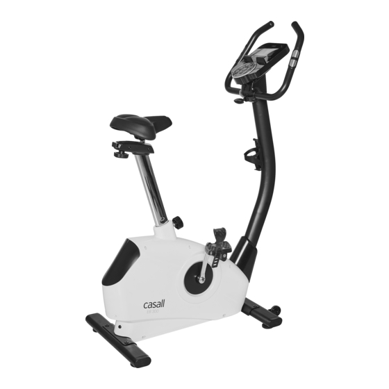
- Page 1 Casall EB300 Bike 91034...
- Page 2 Important: Please locate your serial number and record in the box below for service support purposes. Serial number here:...
- Page 3 91034/EB300 N-4 Box spanner (1) N-3 Allen bolt M8xP1.25x16L (4) N-6 Allen key (1) N-1 T-shape knob M8x69L (1) N-5 Screwdriver (1) (MM)
- Page 4 EXPLODED DIAGRAM...
-
Page 5: Parts List
PARTS LIST Description Q'TY Console & Screw A, A-1 Hex. Screw Shaft Belt pulley Bushing Flywheel set C-1~C-13 Hex screw M6xP1.0x12L Idler wheel Wave washer φ10.5xφ15x0.3t Nylon nut M8 Hex screw M8xP1.25x18L Flat washer φ8.5xφ25x1t Flat washer φ6xφ12x1t Spring for idler Idler lever Semicircle washer φ8xφ19x2t Allen bolt M8xP1.25x16L... - Page 6 Sensor holder G-23 Cover for handlebar post G-24 Flat washer φ5xφ10x1t G-25 Upper console cable Handlebar post Screw M5xP0.8x20L Front cover for console Rear cover for console Bottle holder End cap for rear stabilizer Screw 3/16″x11/8" Adjustment pad Rear stabilizer End cap for front stabilizer Front stabilizer Nylon nut M8...
-
Page 7: Step 2 Pedal Assembly
Step 1 Foot Tube Assembly 1. Attach the front stabilizer (J-2) to the main frame (G-9) using two M8x16 Allen bolts (N-3). 2. Attach the rear stabilizer (I-4) to the main frame (G-9) using two M8x16 Allen bolts (N-3). N-3 M8x16L N-6 Allen key Step 2 Pedal Assembly 1. - Page 8 Step 3 --Seat Tube Assembly 1. Assemble the seat (G-6) to the slider. The slider can be adjusted in different angles. Tighten the two nuts under the seat using a screwdriver. In addition, the slider can be adjusted at a horizontal level by loosening the knob.
- Page 9 Step 4-Handlebar post assembly 1. Please remove the M8x16 Allen bolt (E-2), semicircle washers (E-1) and flat washers (E-3) from the main frame (G-9). 2. Take the handlebar post cover (G-24) and pass it through the handlebar post (H-2). 3. Hold the handlebar post (H-2) and connect the lower console cable (G-20) to the upper console cable (H-1).
- Page 10 Step 5- Handlebar and Computer and Water holder Assembly 1. Pass the hand-pulse wire (M-4) through the handlebar post hole. 2. Attach the handlebar (M-6) to the handlebar post (H-2). 3. Attach the front cover (H-5) and the T-Knob (N-1) clamp by fixing the screws (H-3) to the handlebar post (H-2).
- Page 11 SM1790-67 SERIES INSTRUCTION MANUAL DISPLAY FUNCTIONS ITEM DESCRIPTION TIME Count up – No preset target, Time will count up from 00:00 to maximum 99:59 with each increment being 1 minute. Count down – If you are training with preset Time, Time will count down fro reset to 00:00.
-
Page 12: Key Function
KEY FUNCTION ITEM DESCRIPTION Increase resistance level Setting selection. (Encoder) Down Decrease resistance level (Encoder) Setting selection. Mode / Enter Confirm setting or selection. Press and hold for 2 seconds, the computer will reboot and start from user setting. Reset Go back to the main menu during the presetting of your workout value or stop mode. -
Page 13: Workout Selection
OPERATION: POWER ON Plug in the power supply, the computer will power on and display all segments on LCD for 2 seconds (Drawing 1). Drawing 1 WORKOUT SELECTION Use UP or DOWN (Encoder) to select to workout manually (Drawing2)Program (Drawing 3) User Program (Drawing 4)... - Page 14 Drawing 9 Drawing 10 Drawing 11 Program Mode 1. Use UP or DOWN (Encoder) to select your workout program, choose Beginner mode and press MODE / ENTER to get into. 2. Use UP or DOWN (Encoder) to select program 1~12 (Drawing 12) and press MODE / ENTER...
- Page 15 H.R.C. Mode 1. Use UP or DOWN (Encoder) to select your workout program, choose H.R.C. and press MODE / ENTER to get in. 2. Use UP or DOWN (Encoder) to set your age (Drawing 14). 3. Use UP or DOWN (Encoder) to select 55%.75%.90% or TAG (TARGET H.R.) (default : 100, Drawing 15).
- Page 16 RECOVERY After exercising for a period, keep holding on the hand grips and press the RECOVERY key. The display will stop showing any functions except for “TIME”. Time starts counting down from 00:60 to 00:00 (Drawing 17). The screen will display your heart rate recovery status with F1, F2…. to F6. F1 is the best, F6 is the worst (Drawing 18).
Need help?
Do you have a question about the EB300 and is the answer not in the manual?
Questions and answers