Advertisement
Quick Links
Advertisement

Related Manuals for Casall GRAVITY 1.2X


Summary of Contents for Casall GRAVITY 1.2X
- Page 1 GRAVITY 1.2X CROSSTRAINER USER MANUAL...
- Page 2 Customer, e are pleased that you have chosen a Casall Fitness Equipment. This quality product has been designed for in-home use and has been tested and certified according to the European Norm EN 957-1/6. Please carefully read the instructions prior to assembly and first use and be sure to keep the instructions for reference and maintenance.
- Page 3 Please have the product model name, number and serial number ready when you call. Advice The owner’s manual is only for the customer reference. Casall cannot be held responsible for mistakes due to translation or changes in technical specification of the product.
- Page 4 Product-Preparation: Follow the steps of the assembly instruction carefully. Product-Preparation: Only use suitable tools for assembly and ask for assistance if necessary. Product-Preparation: Only use original Casall parts as delivered (see checklist). Use-Preparation: Tighten all adjustable parts to prevent sudden movement while training.
- Page 5 For this reason, worn or damaged parts should be replaced immediately and the equipment taken out of use until this has been done. Product-Maintenance: Only use original Casall spare parts. Product-Maintenance: Do not under any circumstances carry out electrical repairs or alterations yourself.
- Page 6 A.CONTENTS CHECKLIST...
- Page 7 B. HARD ARE COMPARISON CHART...
-
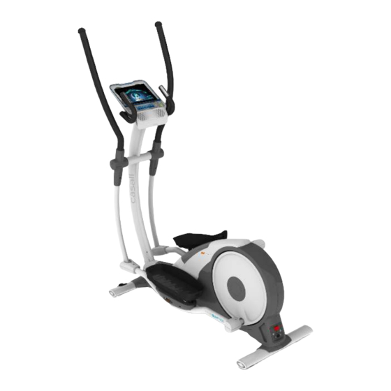
Page 8: Power Switch
Elliptical parts guideline Action Handlebar Hand pulse sensor iPad frame Loud Speaker Foot Plate Power switch Foot Plate Tube Rear Stabilizer tube... - Page 9 Front Foot Plate Tube front Cover Transportation wheel Front Stabilizer tube...
-
Page 10: Assembly Instruction
Assembly Instruction... - Page 22 Assembly complete...
- Page 23 ower Connecting the power cord for Bike and turn on the power switch.
- Page 24 lay music This home-trainer comes with loud speaker , connceting the MP3 audio data line for iPad or mobile device with MP3 audio output to enjoy music. There is an USB jack at the right side of console. It can charge electronic devices once connect the USB cable.
- Page 25 Transport and adjustment foot...
- Page 27 Correct Use roper Ergonomic ositioning: Please refer to the diagram to the left as indication of the proper training position. Mount and dismount the equipment: Select any flank of the equipment, which flank you can easy and comfortable to move your foot to mount on or dismount from the equipment. Make sure you step on the pedal in the lowest position steadily and hold the handle bars firmly.
-
Page 28: Wiring Diagram
Wiring diagram... -
Page 29: Exploded View
Exploded view... - Page 32 Spare art List Part No. DESCRIPTION Q'ty per unit Front Stabilizer tube Rear Stabilizer tube Transportation Wheel set Front Stabilizer Tube End Cap Front Stabilizer Tube Foot Rear Stabilizer Tube Adjustment Foot 6004 Bearing Crank shaft bushing Main frame Bushing Ø21X29X33.5 Speed sensor Holder-OD6X40X10 T-2.0 Console rear cover Console housing-Lower...
- Page 33 Upright Axle Bushing Upright tube Console support tube 6203 Bearing Console Upright Insert Bearing holder- ID22XOD47XT20 Bushing-ID18XOD21X64.5 Bearing holder-ID26XOD47XT23 Bearing bushing Hand Pulse cover Console support tube end cap Foot Plate Crank Crank Shaft Plate Driving Belt large pulley Driving Belt-630J-6 Crank Shaft Pedal buffer Pedal soft cushion...
- Page 34 Main Chain Cover- Right Front Chain Cover- Right Side cover-outside Switch Board plastic cover Switch Board Buffer set sleeve-10X63.4 Right side Chain Cover- Rear Crank disk Front Foot Plate Tube front Cover- Upper Front Foot Plate Tube front Cover-Lower Foot Plate side cover Bearing Holder-ID40XOD47X39 Adjustable Bearing 2203 Rear Foot Plate Tube Rear Cover-Lower...
- Page 35 Tension Bracket Adjustment Base 6300 Bearing Flywheel D-shaped Holder-48X24XT2.5 Spring Nut 7 PIN cable-Upper 7 PIN cable-Lower Power cable-500mm Single wire-red-80mm Single wire-white-50mm Grounding wire-150mm Control board Transformer Speed sensor wire Electric outlet Power switch Electric protector Electromagnet Foot Plate Tube Sleeve M10x67mm M4X15 Screw M4X19 Screw Outer hexagon screw M8X45x25...
- Page 36 M5X12 screw/washer M4X15 Screw Round head cross- screw M6X6 Washer 8X23X2 Spring washer 8X 14 X2 Button head inner hexagon screw M8X15- Inner hexagon M12X50 Round head cross- screw M3X12 Flange outer hexagonal screws M6X14 Cylinder -head inner hexagon screws M8X30 Flat-head inner hexagon screws M10X39 Locknut M10...
- Page 37 Spring 4.5x 25 x74.47 Button head inner hexagon screw MM8X12 Locknut M8 Round head cross- screw M4X12 Cylinder -head inner hexagon screws M6X10 Cylinder -head inner hexagon screws M8X50 Nut M8 Round head cross- screw M8X20 Plastic insert-OD6X12-9X3 Shrapnel 21X13X0.7 Thin Nut M8 Cross screw M8X25 Power cord...
- Page 38 Computer operation instructions...
- Page 39 Before assembling or using your fitness equipment, please carefully read the precautions included in the assembly instruction. DISPLAY (1)WATT/ ROGRAM/ ISTANCE The display range of the ATT is from 10 to 400. Program display from Program 1 to Program 8. The DISTANCE display range is from 0.0 to 99.9 kilometres.
- Page 40 ( ) HEIGHT HEIGHT display range is from 50 to 220 cm. the initial HEIGHT is 160 cm. ( ) RECOM. WEIGHT The recommended body weight based on standard BMI. (5) TIME The TIME display range is from 0:00 to 99:00. The initial TIME is “32:00”.
- Page 41 BUTTONS AN FUNCTIONS START button Press START to begin your exercise. STO button Press STOP button to pause the functions during your exercise program. Press STOP button twice the program will return to power on mode. RESISTANCE up button Press the button to increase the RESISTANCE level or set up the program. RESISTANCE down button Press the button to reduce the RESISTANCE level or set up the program.
-
Page 42: Quick Start
OWER ON Connecting the power cable and turning on the power switch at the rear of machine. The LCD screen will light up. QUICK START hen the computer is in the PO ER ON STATUS, press the start button to activate the QUICK START program, the TIME, DISTANCE and CALORIES will count up from zero when you start exercising. - Page 43 icon on the App or press the “ENTER” button on the computer key board. The “I M” will be shown and flashing on the computer LCD screen. Press the RESISTANCE UP/DO N button to select one of the program. Then computer LCD screen will show I M→P1→P2→P3→P4→P5→P6→P7→P8”(Scan ), there is no I M program display when App has been linked successfully.
- Page 44 The Body Mass Index Introduction: Body Mass Index (BMI) is used to assess how much an individual's body weight departs from what is normal or desirable for his or her height. This weight excess or deficiency may, in part be accounted for by body fat. Although other factors such as muscularity also effect BMI significantly.
- Page 45 USER " I " After the USER EIGHT has been confirmed, “USER” display will blink. You will need to select the USER CODE first, press the UP/DO N button to select the USER CODE from U1 to U6. This is shown in the SPEED display.
- Page 46 After finishing user profile set up, the console will display the recommend user weight on “RECOM.” weight numbers that calculated through user height based on standard BMI. You can compare the exact body weight and recommend body weight. Console would also automatically generate the personalized workout program with target calories.
- Page 47 Power on the computer, press the ENTER button, then the I M will be flashing. Press the RESISTANCE UP/DO N button to select the P1(Program 1) , then press the ENTER button again, computer will go to P1 procedure. eight setting hen the P1 display on the computer display screen dot matrix area, users press the ENTER button, the figure”0.0”...
- Page 48 To pause the program while exercising, press the STOP button. To resume exercising, press the “START” button. The time counts down at the end of the program the computer will “beep”. 2: Target distance program Power on the computer, press the ENTER button, then the I M will be flashing. Press the RESISTANCE UP/DO N button to select the P2(Program 2) , then press the ENTER button again, computer will go to P2 procedure.
- Page 49 and present all the time. Press the “MODE” button again, the ( DIST. ) , (RPM ) and ( SPD. ) will be shown on the computer display screen and be present all the time. Press the “MODE” button for the third time, computer display screen figures will come back to scan status automatically.
- Page 50 All exercise figures will be displayed on the computer display screen when you start to do exercise, and the figures will be scan automatically during exercise. To switch the screen display while exercising, press the “MODE” button to switch the “( ATT / DIST.
- Page 51 After inputting weight, press the ENTER button to confirm. After you have selected “P4-Random program” press the “ENTER” button. The TIME will show the workout time setting of “32:00”. Press the RESISTANCE “UP /DO N” button to adjust workout time, then press the “ENTER”...
- Page 52 procedure. eight setting hen the P5 display on the computer display screen dot matrix area, please press the ENTER button, the figure”0.0” and the dot will be flashing at EIGHT. Press the RESISTANCE “UP /DO N“ button to input the weight and press the ENTER button to confirm.
- Page 53 Press the “MODE” button first, the ATT , PULSE and CAL. will be shown on the computer display screen and present all the time. Press the “MODE” button again, the ( DIST. ) , (RPM ) and ( SPD. ) will be shown on the computer display screen and present all the time.
- Page 54 time will count down to the end. The DISTANCE and CALORIES display will count up from 0. All exercise figures will be displayed on the computer display screen when you start to do exercise, and the figures will be scan automatically during exercise. To switch the screen display while exercising, press the “MODE”...
- Page 55 weight and press the ENTER button to confirm. Time setting After inputting weight, press the ENTER button to confirm. After the user has selected “P7 Endurance program “, the TIME display will show the workout time setting of “16:00”, press the “UP /DO N ” button to adjust workout time then press “ENTER” to confirm. Press the ”START”...
- Page 56 : Heart Rate Control program Power on the computer, press the ENTER button, then the I M will be flashing. Press the RESISTANCE UP/DO N button to select the P8 (Program 8) , then press the ENTER button again, computer will go to P8 procedure.
- Page 57 to confirm. Press the “START” button to begin exercise program. If the pulse is not detected by hand pulse sensor, the PULSE” display will show the “P” and flashing. The RESISTANCE display will show the Level the user has set. To increase or decrease the RESISTANCE while exercising, press the RESISTANCE “UP/DO N” button.
- Page 58 After completing the TIME set up and starting the program, there is a total 3 minute warm up section. The ARM UP section will help you reach the target workout PULSE. The RESISTANCE will start from 25 ATTS. hen the “warm up” section starts, the LCD display will show the words “warm up”. hen the user uses the “...
- Page 59 section, the computer will go into the main program and the time will count down from the pre-set time. During the main program, the computer will detect the user pulse rate every 30 seconds. The time will count down to the end. The DISTANCE, CALORIES will continue to count up from the “ arm up” section into the Target pulse Program.
- Page 60 The Cross trainer comes with EKG hand pulse sensors which can be found on the handlebars. To operate pulse rate function, place the palms of your hands over the sensors. It will take a few seconds for your pulse rate to be displayed on the console. To keep monitoring, keep gripping the sensors. If the readings are intermittent you may not have full contact with the sensors or not enough of your palm on the sensor.
- Page 61 Heart Rate diagram You can calculate the target-heart rate for your training as follows: Maximum heart rate = 220 minus age For the different training targets you should train with the following percentage of your maximum heart rate: Health/Fat Burning: 50 –...
- Page 62 70% of 195 = 1 ,5 0% of 195 = 15 Your target-heart rate should be between 136,5 and 156 beats per minute. This information is for your reference only. To determine your individual training intensity or in case you should have health restrictions please consult your physician before starting exercising...
Need help?
Do you have a question about the GRAVITY 1.2X and is the answer not in the manual?
Questions and answers