Advertisement
Quick Links
Advertisement

Related Manuals for Casall EB100


Summary of Contents for Casall EB100
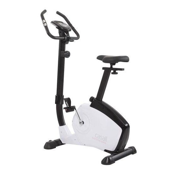
- Page 1 Casall EB100 Bike 91033...
- Page 2 Important: Please locate your serial number and record in the box below for service support purposes. Serial number Serial number here:...
- Page 3 91033 (EB100) I-5 Flat washer Ø7(2) I-10 Allen bolt M7xP1.0x30mm (1) I-4 Metal cover (1) I-3 Carriage bolt M8xP1.25x55mm (4) I-9 T-shape knob M7x65L(1) I-2 Flat washer Ø8xØ19x2t (4) I-8 Bushing Ø12x40mm (1) I-1 Acorn nut (4) Screwdriver (1) Box spanner (1) I-6 Spring Washer Ø7(2)
-
Page 4: Exploded Diagram
EXPLODED DIAGRAM... -
Page 5: Parts List
PARTS LIST Description Q'TY A, A-1 Console & screw Screw Handlebar Foam grip Cap for handlebar Wire for hand pulse Hand pulse Screw M4x20L Handlebar post Upper sensor wire Tension control Semicircle washer φ8xφ19x2t Allen bolt M8xP1.25x16L Bottle holder Screw M5x20L Main frame Adjustment knob Sensor box (Lower sensor wire) - Page 6 Flat washer φ8.5xφ25x1t Nylon nut M8 Spring for idler Front stabilizer Left end cap for front stabilizer Right end cap for front stabilizer Screw 3/16" Rear stabilizer End cap for rear stabilizer Adjustment pad I-1~I-10 Hardware pack Seat post Plastic bushing Knob for seat slider Flat washer φ12.5xφ20x2t Fixing screw seat for seat slider...
- Page 7 Step 1 1. Attach the front stabilizer (G) to the main frame (D) using two carriage bolts (I-3), flat washers (I-2) and acorn nuts (I-1). 2. Attach the rear stabilizer (H) to the main frame (D) using two carriage bolts (I-3), flat washers (I-2) and acorn nuts (I-1).
- Page 8 Step 3 1. Assemble the seat (J-7) to the slider. The slider can be adjusted in different angles. Tighten the two nuts under the seat using a screwdriver. In addition, the slider can be adjusted at a horizontal level by loosening the knob. 2.
- Page 9 Step 4 1. Please r emove the Allen bolt ( C-5) a nd semicircle washers (C-4) f rom t he main f rame (D) 2 8 T 2 8 T 2 8 T 2 8 T 2 8 T 2 8 T 2 8 T 2 8 T 2 8 T...
- Page 10 Step 5 1. Pass the hand-pulse wire (B-3) through the hole. 2. Attach the handlebar (B) to the handlebar post (C-1) using the metal clamp (I-4). Fix it firmly with one flat washer (I-5), one spring washer (I-6) and one fixing bolt (I-10). 3.
- Page 11 ST6515-67 INSTRUCTION MANUAL DISPLAY FUNCTION : ITEM DESCRIPTION . The display sequence: RPM→SPEED→TIME→ DISTANCE →CALORIES→PULSE SCAN In SCAN mode, press MODE key to choose other functions. . Automatically scan through each mode in sequence every 6 seconds. . W/O setting the target value, time will count up. .
- Page 12 . There will be a pulse alarm when you over preset target pulse. . Range 0~230 . Display “ “ when the monitor stop for 4 seconds. STOP(P) K EYS: ITEM DESCRIPTION . Press and hold the button to increase the value faster .
Need help?
Do you have a question about the EB100 and is the answer not in the manual?
Questions and answers