Advertisement
Quick Links
Advertisement

Related Manuals for Casall EB200


Summary of Contents for Casall EB200
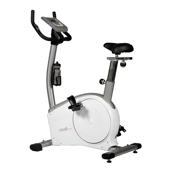
- Page 1 Casall EB200 Bike 91001...
- Page 2 Important: Please locate your serial number and record in the box below for service support purposes. Serial number here: ...
- Page 3 EB200 No:J-4 Allen Bolt No:J-6 Spring Washer M7*P1.0*30L (1) NO:J-1 Aorra Nut for M8 Bolt(4) φ 7*2t(2) No:J-8 C-shape knob M7*55L(1) No:J-4 C-shape knob M7*65L(1) No:J Metal cover (1) No:J-5 Regular Washer φ 7*1t(2) Screwdriver (1) NO:J-2 Carriage Bolt M8*1.25*55L(4)
-
Page 4: Assembly Diagram
Assembly Diagram... - Page 5 EXPLODED DIAGRAM EB200 No:J-4 Allen Bolt No:J-6 Spring Washer M7*P1.0*30L (1) N O:J-1 Aorra Nut for M8 Bolt(4) 7*2t(2) No:J-8 C-shape knob M7*65L(1) No:J Metal cover (1) No:J-5 Regular Washer No:J-7 Bushing φ12*40L (1) 7*1t(2) N O:J-2 Carriage Bolt M8*1.25*55L(4)
-
Page 6: Parts List
PARTS LIST Description Specifications Q'TY A-1,A-2 COMPUTER & SCREW HANDLEBAR HAND PULSE SET 1SET FOAM GRIP 480xφ20x5.0m/m 1SET CAP FOR HANDBLEBAR 1SET HAND PULSE WIRE 550+550mm HANDLEBAR POST COMPUTER CABLE (UPPER) BOTTLE HOLDER SCREW FOR R/L COVER M5xP0.8x14L 2PCS REAR COVER FOR COMPUTER FRONT COVER FOR COMPUTER SCREW FOR BOTTLE HOLDER M5xP0.8x20L... - Page 7 D-26 CROSS DISC (L) E~E-12 FLYWHEEL SET 1SET FRONT STABILIZER SET 1SET REAR STABILIZER SET 1SET SEAT POST SET 1SET G-1~G-5 SEAT SLIDER 1SET SEAT H-RL PEDAL 1SET I~I-9 IDLER WHEEL SET 1SET J~J-9 BOLTS & NUTS PACK 1SET ADAPTOR M~M-13,D-1 GEAR BOX AND MAGNETIC SET...
- Page 8 Step 1 Foot Tube Assembly Attach the Front Stabilizer (pt.F-F) to the Main Frame (pt.D) using two M8xP1.25x55L carriage bolts (pt.J-2),Flat washer (pt.J-3) and nuts (pt.J-1). Attach the Rear Stabilizer (pt.F-B) to the Main Frame (pt.D) using two M8xP1.25x55L carriage bolts (pt.J-2),Flat washer (pt.J-3) and nuts (pt.J-1).
- Page 9 Step 3 --Seat Tube Assembly 1. Please remove the adjusting knob (pt.D-4) from the main frame (pt.D). 2. Assemble the seat (pt.G-6) to the Slider. The slider can be adjusted in different angles. Tighten the two Nuts under the Seat using a screwdriver. In addition, the Slider can be adjusted in horizontal level by loosing the knob.
- Page 10 Step 4-Handlebar post Assembly 1. Please remove the M8*16L Allen bolt (pt.D-2) and Semicircle washers (pt.D-3) from the main frame (pt.D) 2. Hold the Handlebar post (pt.C) and connect the Lower computer cable (pt.D-1) to the Upper computer cable (pt. C-1) 3.
- Page 11 Step 5- Computer and Bottle holder Assembly 1. Connect the Computer cables (pt .C-1) to the Computer (pt.A). Then attach the Computer (pt .A) to the Computer bracket with the enclosed Screws (pt. A-1). 2. Remove the pre-installed Screws (pt.C-6) on the handlebar post first, and then assemble the Bottle holder (pt.C-2) using screw (pt.
- Page 12 Step 6- Handlebar Assembly 1. Attach the Handlebar (pt.B) to the Handlebar post (pt.C) using the Metal cover (pt.J). Fix firmly with one Flat washer (pt.J-5), one Spring washer (pt.J-6) and one Fixing bolt (pt.J-4). 2. Attach the Rear cover (pt.C-4) to the Handlebar post (pt.C) using two of M3x14L Screws (pt.J-9) and one of M5xP0.8x14L Screws (pt.C-3) .
- Page 13 INSTRUCTIONAL MANUAL FOR CASALL EB200 CONSOLE...
- Page 14 DISPLAY FUNCTIONS : ITEM DESCRIPTION TIME .Workout time displayed during exercise. .Range 0:00 ~ 99:59 SPEED .Workout speed displayed during exercise. .Range 0.0 ~ 99.9 KM/Hour DISTANCE .Workout distance displayed during exercise. .Range 0.00 ~ 99.90 KM CALORIES .Burned calories during workout display. .Range 0 ~ 990 Cals * Calorie count on the display only serves as a general guideline.
- Page 15 OPERATION: POWER ON Plug in power supply, computer will power on and display all segments on LCD for 2 seconds. After 4 minutes without pedaling or pulse input, console will enter into power saving mode. Press any key may wake the console up. Manual Mode Adjust resistance during workout manually.
- Page 16 Press UP or DOWN to set load level of each column, and press MODE to next one. Hold on pressing MODE to finish or quit setting. Press UP or DOWN to preset workout TIME. Press START/STOP key to start workout. Press UP or DOWN to adjust load level. Press START/STOP key to pause workout.
- Page 17 Recovery Monitor heart rate recovery status. 1. User must be holding the handgrip. When the pulse value is displayed on the computer, press on the RECOVERY key. 2. TIME shows "0:60" (seconds) and count down. 3. Computer will show F1 to F6 after count down to 0 to test heart rate recovery status. <Trouble shooting>...
Need help?
Do you have a question about the EB200 and is the answer not in the manual?
Questions and answers