ZANOLLI Citizen 6/MC Instructions For Installation, Use And Maintenance Manual
Electromechanical/electronic pizza and delicatessen ovens
Hide thumbs
Also See for Citizen 6/MC:
- Installation, use and maintenance manual (43 pages) ,
- Installation, use and maintenance manual (40 pages)
Table of Contents
Advertisement
Advertisement
Table of Contents

Related Manuals for ZANOLLI Citizen 6/MC


Summary of Contents for ZANOLLI Citizen 6/MC
- Page 1 DR. ZANOLLI s.r.l. Via Casa Quindici, 22 37060 Caselle di Sommacampagna (Verona) Italy Tel +39 045 8581500 (r.a.) Fax +39 045 8581455 Web: www.zanolli.it • e-mail: zanolli@zanolli.it CITIZEN 6 - 9/MC Electromechanical/electronic Pizza and delicatessen ovens Installation, use and maintenance manual...
- Page 2 Casa Quindici 22 37060 Caselle di Sommacampagna VR Tel. +39-0458581500 Fax +39-0458581455 VAT N.IT00213620230 Citizen 6 - 9/MC English manual cod. CITM.E.EM-D.UK.06 rev. 0.2 del 20/04/11...
-
Page 3: Table Of Contents
_________________________________________________________________________INDEX INDEX INDEX....................3 1.INTRODUCTION ................6 2.HOW TO USE THIS MANUAL............7 3.SPECIFICATIONS ................9 3.1.P ................. 9 RODUCT IDENTIFICATION 3.2.C ..............9 ONFORMITY TO DIRECTIVES 3.3.E ..................9 NVISAGED USE 3.4.T ..............10 ECHNICAL SPECIFICATIONS 4.INSTALLATION WARNINGS .............11 4.1.D ................. 11 ELIVERY CHECKS 4.2.C .......... - Page 4 _________________________________________________________________________INDEX 6.2.4.Temperature control Baking chamber temperature display..17 6.2.5. Set button, Push-button of ESC..........17 6.2.6. buttons ................18 6.2.7. OUT display ..................18 6.2.8.Power regulators ................18 6.2.9.Oven roof and bedplate pilot lamps..........19 6.3.E ..................19 RROR DISPLAY 6.3.1.Short-circuited thermocouple ...............19 6.3.2.Disconnected thermocouple .................19 7.ELECTRONIC VERSION OPERATION........20 7.1.C ..................
- Page 5 _________________________________________________________________________INDEX 9.1.C ....27 LEANING OF ANY VISIBLE GLASS AND STAINLESS STEEL PARTS 9.2.C ........... 27 LEANING OF ANY REFRACTORY PARTS 9.3.C ’ ..........28 LEANING THE OVEN S BAKING CHAMBER 9.4.C ............28 LEANING THE EXTERNAL SURFACE 10.MAINTENANCE ................29 10.1.O ............
-
Page 6: Introduction
______________________________________________________________1. INTRODUCTION 1.INTRODUCTION The modular “CITIZEN” ovens represent the new way of making traditional pizza ovens. They are designed and manufactured to demanding mechanical and electrical standards and are built to last. “CITIZEN” has been designed with the user in mind. “CITIZEN”... -
Page 7: How To Use This Manual
____________________________________________________2. HOW TO USE THIS MANUAL 2.HOW TO USE THIS MANUAL This manual should be kept near to the equipment itself so it can be quickly and easily consulted. The manual must travel with the equipment if it is moved to another owner as the latter may not be considered complete or safe without it. - Page 8 ____________________________________________________2. HOW TO USE THIS MANUAL Chapters 6 and 7 is for reference whenever the user wishes to clarify specific aspects of the equipment operation. It is not advisable to use these chapters as a way to learn how to use the equipment. Chapter 8 is useful for the user who has to learn to use the oven from scratch.
-
Page 9: Specifications
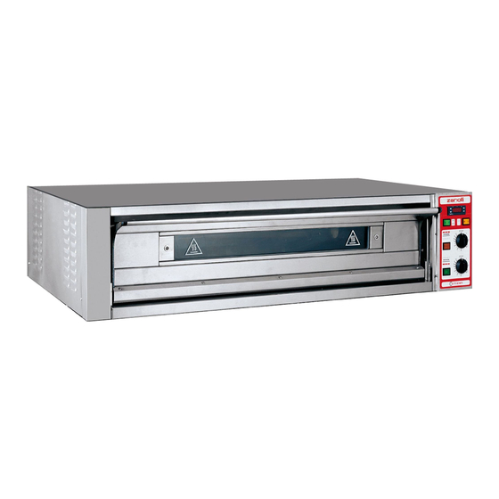
The single deck Citizen 6/MC and Citizen 9/MC are intended for professional use in the catering sector (Restaurants, pizzerias, confectionery’s shops, etc.) and are exclusively intended to be used by qualified staff. -
Page 10: Technical Specifications
_____________________________________________________________3. SPECIFICATIONS 3.4.Technical specifications The following table shows the baking modules’ technical specifications. Citizen 6/MC Citizen 9/MC Units of measurement Weight External dimensions 1376×1025×411 1376×1310×411 mm Cooking chamber size 1050×700×155 1050×1050×155 mm Capacity (pizzas Ø30cm) n° three-phase or three-phase + neutral... -
Page 11: Installation Warnings
_____________________________________________________4. INSTALLATION WORNINGS 4.INSTALLATION WARNINGS WARNING: These installation instructions are intended only for staff which is qualified for the installation and the maintenance of electrical and/or gas plants. Installation by any other person may cause damage to the equipment, persons, animals or things. Furthermore in the place where you have to install the equipment, it is necessary to make any modifications or additions to the electrical and/or gas plant in the building in which the equipment is being installed, the person... -
Page 12: Electrical Connection
_____________________________________________________4. INSTALLATION WORNINGS must be free of encumbrances. In particular it is necessary to avoid obstructing the cooling apertures.( Figure 5.1). The equipment must in any case be installed at least 2 cm from the walls of the room and from other equipment. Finally it is necessary to ensure that the temperature and relative humidity of the place in which the equipment is installed must never exceed the maximum and minimum values indicated in the specifications section... -
Page 13: Installation
(Figure 5.1.). In choosing the place to install the single deck Citizen 6/MC and Citizen 9/MC bear in mind they have to be completed with the addition of other modules from the series (Hood, prover etc.). -
Page 14: Connecting The Steam Outlet
5.4.Mounting the module steam outlet electrical cable input a mm b mm c mm w mm Citizen 6/MC 1370 Citizen 9/MC 1083 1370 Fig. 5.3.Position of electrical cable input, steam outlet and plate. Position the modules one above the other in the right order ( prover or base, baking module, hood) and fix by means of the accompanying hooks and screws. -
Page 15: Checks Before Starting Up Electromechanical Version
_______________________________________________________________5. INSTALLATION 5.6.Checks before starting up electromechanical version. Turn on the main switch on the switchboard. Turn on the switch (6.2.1.), program a temperature above 100-120 °C (6.2.4.), set both the power regulators at 10. Check that the current to each phase is that indicated in chapter 3., for the corresponding feed voltage. -
Page 16: Working Electromechanical Version
______________________________________6. WORKING ELECTROMECHANICAL VERSION 6.WORKING electromechanical version 6.1.Control panel Figure 6.1. shows the control panel with all controls: 6.1.1.Temperature control Baking chamber temperature display Set button Up button Down button Out display 6.1.2.General Baking chamber light switch Baking chamber on/off switch Switch for suction hood 6.1.3.Power control Oven roof power regulator and... -
Page 17: Baking Chamber Light Switch
______________________________________6. WORKING ELECTROMECHANICAL VERSION chamber heating elements turn on according to the set temperature and power. 6.2.2. Baking chamber light switch By setting switch on ON, the switch and the chamber light turn on. 6.2.3. Switch for suction hood The switch for suction hood control is placed on the side part of the control panel, on the upper side (Pos.1 of Fig. -
Page 18: And Buttons
______________________________________6. WORKING ELECTROMECHANICAL VERSION 6.2.6. buttons By pressing and releasing these buttons once, the set temperature increases or decreases by one unit. By keeping them pressed, the set temperature increases or decreases progressively, slowly at first and then faster. 6.2.7. OUT display display turns on every time the baking chamber temperature is below the set temperature. -
Page 19: Oven Roof And Bedplate Pilot Lamps
______________________________________6. WORKING ELECTROMECHANICAL VERSION 6.2.9.Oven roof and bedplate pilot lamps Both oven roof and bedplate pilot lamps turn on when the display is on and its power regulator is switching on within the regulation cycle, to indicate that its heating element is actually on. power regulation position no. -
Page 20: Electronic Version Operation
_______________________________________________7. WORKING ELECTRONIC VERSION 7.ELECTRONIC VERSION OPERATION 7.1.Control panel The picture 7.1. shows the control panel with all controls: Display of oven temperature / setting temperature Display of oven top heating elements control Display of oven bottom heating elements control Key of parameter programme input Key of parameter increment Key of parameter decrement... -
Page 21: Ctivity And Inactivity State
_______________________________________________7. WORKING ELECTRONIC VERSION 7.2.Activity and inactivity state on/off of main system During the inactivity state the card is powered but no functions foreseen by the system can be enabled, since the electromagnetic switch is not enabled yet. The display of the control panel will show the writing "OFF". -
Page 22: Main On/Off Light Switch
_______________________________________________7. WORKING ELECTRONIC VERSION Press again the key to enter the datum into memory. The parameter is shown in fixed mode and the display relating to the oven bottom heating element starts to blink. Use the keys until you read the desired parameter on the display. -
Page 23: Key Chamber Light
_______________________________________________7. WORKING ELECTRONIC VERSION 7.3.5.Key chamber light By pressing the key of the chamber light you activate the turning on of the lamp placed inside the baking chamber. By pressing it again, you deactivate it. 7.3.6. Switch for suction hood The switch for suction hood control is placed on the side part of the control panel, on the upper side (Pos.1 of Fig. -
Page 24: Use
_________________________________________________________________________8. USE 8.USE 8.1.Preparation for use If the equipment has just been installed or has not been used for a number of days, before using it for food products, it is necessary to clean it thoroughly in accordance with the indications in chapter 9 to remove residual factory dirt, accumulations of dust or any other substances which could contaminate food products. -
Page 25: Baking Start
_________________________________________________________________________8. USE 8.4.Baking start For the electromechanical version: at this point turn on the light switch For the electronic version: the oven is already active (ignition of the control panel after pressing the key ): you will see that the temperature of the chamber starts to rise. -
Page 26: Turning Off
_________________________________________________________________________8. USE any case if the oven is used within the limits of its maximum capacity, the temperature will start to rise again towards the end of the cooking time. 4) the oven has a maximum production capacity expressed indicatively in the characteristics in Kg off product per hour ( chapter 3.). -
Page 27: Cleaning
___________________________________________________________________9. CLEANING 9.CLEANING At the end of each working day (or more frequently if possible) it is necessary to carefully clean the cooking surface and all the parts of the oven which come into contact with the food being cooked to avoid that any food substances go off and contaminate either the working environment or later products to be cooked. -
Page 28: Leaning The Ovens Baking Chamber
___________________________________________________________________9. CLEANING 9.3.Cleaning the oven’s baking chamber Use a soft damp sponge to clean the stainless steel or aluminium plate baking chamber, if necessary with a light, non abrasive detergent, being careful that it does not splash onto any refractory surfaces. If there are substantial deposit of grease or fat, remove them carefully beforehand with a spatula. -
Page 29: Maintenance
______________________________________________________________10. MAINTENANCE 10.MAINTENANCE WARNING: These use and maintenance instructions are intended only for staff which is qualified for the installation and maintenance of electrical and gas equipment. Maintenance by other persons may cause damage to the equipment, persons, animals or things. In the majority of cases it is necessary to remove the fixed guards in order to carry out repairs and checks. -
Page 30: Error Displays
______________________________________________________________10. MAINTENANCE 10.2.Error displays The electronic control is able to detect some failures, for details see 6.3 for the electromechanical version or 7.4 for the electronic version. 10.3.Electrical diagram 10.3.1.Electromechanical version Figures 10-1, 10-2, 10-3, 10-4, 10-5, 10-6 shows the electrical diagrams of the Citizen series: 6/MC e 9/MC for the 400Vac 3-N, 230Vac 3 and 230Vac 1- N electromechanical versions. -
Page 31: Attachment Of New Label
The exploded views Figure 10-13,10-14, 10-15 e TAB10.1 refer to the baking module Citizen 6/MC (electronic/electromechanical version), but the indications are also valid for the other versions. ______________________________________________________________________________... - Page 32 ______________________________________________________________10. MAINTENANCE Figure 10-1.Electrical diagram for Citizen 6/MC at 400 Vac. 3-N (electromechanical version). ______________________________________________________________________________ CITIZEN 6 - 9/MC...
- Page 33 ______________________________________________________________10. MAINTENANCE Figure 10-2.Electrical diagram for Citizen 6/MC at 230 Vac. 3 (electromechanical version). ______________________________________________________________________________ CITIZEN 6 - 9/MC...
- Page 34 ______________________________________________________________10. MAINTENANCE Figure 10-3.Electrical diagram for Citizen 6/MC at 230 Vac. 1-N (electromechanical version). ______________________________________________________________________________ CITIZEN 6 - 9/MC...
- Page 35 ______________________________________________________________10. MAINTENANCE Figure 10-4.Electrical diagram for Citizen 9/MC at 400 Vac. 3-N (electromechanical version). ______________________________________________________________________________ CITIZEN 6 - 9/MC...
- Page 36 ______________________________________________________________10. MAINTENANCE Figure 10-5.Electrical diagram for Citizen 9/MC at 230 Vac. 3 (electromechanical version). ______________________________________________________________________________ CITIZEN 6 - 9/MC...
- Page 37 ______________________________________________________________10. MAINTENANCE Figure 10-6.Electrical diagram for Citizen 9/MC at 230 Vac. 1-N (electromechanical version). ______________________________________________________________________________ CITIZEN 6 - 9/MC...
- Page 38 ______________________________________________________________10. MAINTENANCE Figure 10-7 Electrical diagram for Citizen 6/MC at 400 Vac. 3-N (electronic version). ______________________________________________________________________________ CITIZEN 6 - 9/MC...
- Page 39 ______________________________________________________________10. MAINTENANCE Figure 10-8 Electrical diagram for Citizen 6/MC at 230 Vac. 3 (electronic version). ______________________________________________________________________________ CITIZEN 6 - 9/MC...
- Page 40 ______________________________________________________________10. MAINTENANCE Figure 10-9 Electrical diagram for Citizen 6/MC at 230 Vac. 1-N (electronic version). ______________________________________________________________________________ CITIZEN 6 - 9/MC...
- Page 41 ______________________________________________________________10. MAINTENANCE Figure10-10 Electrical diagram for Citizen 9/MC at 400 Vac. 1-N (electronic version). ______________________________________________________________________________ CITIZEN 6 - 9/MC...
- Page 42 ______________________________________________________________10. MAINTENANCE Figure10-11 Electrical diagram for Citizen 9/MC at 230 Vac. 3 (electronic version). ______________________________________________________________________________ CITIZEN 6 - 9/MC...
- Page 43 ______________________________________________________________10. MAINTENANCE Fig10-12 Electrical diagram for Citizen 9/MC at 230 Vac. 1-N (electronic version). ______________________________________________________________________________ CITIZEN 6 - 9/MC...
- Page 44 ______________________________________________________________10. MAINTENANCE Figure 10-13 Exploded view electronic\electromechanical version ______________________________________________________________________________ CITIZEN 6 - 9/MC...
- Page 45 ______________________________________________________________10. MAINTENANCE Figure 10-14 Exploded view of electrical parts electromechanical version ______________________________________________________________________________ CITIZEN 6 - 9/MC...
- Page 46 ______________________________________________________________10. MAINTENANCE Figure 10-15 Exploded view of electrical parts electronic version ______________________________________________________________________________ CITIZEN 6 - 9/MC...
- Page 47 ______________________________________________________________10. MAINTENANCE N°. Description Codes Citizen 6/MC Citizen 9/MC GLASS RESTRAINING FRAME CARP0111 CARO0111 LEFT STIRRUP SUPP0206 SUPP0206 DOOR FRAME PORT0202 PORT0202 RIGHT STIRRUP SUPP0207 SUPP0207 FRONT HEATING ELEMENT RESI0077 RESI0077 REAR HEATING ELEMENT RESI0078 RESI0078 LEFT SIDE FIAN0201 FIAN0199...
- Page 48 ______________________________________________________________10. MAINTENANCE N°. Description Codes Citizen 6/MC Citizen 9/MC TERM0014 TERM0014 ENERGY REGULATOR TERM0050 TERM0050 GREEN LIGHT LAMP LAMP0006 LAMP0006 YELLOW LIGHT LAMP LAMP0002 LAMP0002 ENERGY REGULATOR KNOB MANI0021 MANI0021 BIPOLAR SWITCH BRIGHT YELLOW 0-1 INTE0009 INTE0009 BIPOLAR SWITCH BRIGHT GREEN 0-1...
-
Page 49: Decommissioning And Demolition
__________________________________________11. DECOMMISSIONING AND DEMOLITION 11.DECOMMISSIONING AND DEMOLITION Before proceeding with the decommissioning disconnect the electrical supplies to the equipment and any other connections there may be and then move the machines using suitable means such as : forklift trucks, hoists, etc., keeping in mind the position of the centres of gravity (see table 5.1.) indicated in the chapter INSTALLATION (5). -
Page 50: Declaration Of Conformity
______________________________________________12. DECLARATION OF CONFORMITY 12.DECLARATION OF CONFORMITY ______________________________________________________________________________ CITIZEN 6 - 9/MC...
Need help?
Do you have a question about the Citizen 6/MC and is the answer not in the manual?
Questions and answers