ZANOLLI CITIZEN 6/MC Installation, Use And Maintenance Manual
Pizza and delicatessen ovens
Hide thumbs
Also See for CITIZEN 6/MC:
Table of Contents
Advertisement
Quick Links
DR. ZANOLLI s.r.l.
Via Casa Quindici, 22
37066 Caselle di Sommacampagna (Verona) Italy
Tel +39 045 8581500 (r.a.)
Fax +39 045 8581455
Web: www.zanolli.it e-mail: zanolli@zanolli.it
CITIZEN 6 - 9/MC
CITIZEN 6+6 - 9+9/MC
ELECTROMECHANICAL VERSION
Pizza and delicatessen ovens
Installation, use and maintenance manual
Advertisement
Table of Contents

Related Manuals for ZANOLLI CITIZEN 6/MC


Summary of Contents for ZANOLLI CITIZEN 6/MC
- Page 1 DR. ZANOLLI s.r.l. Via Casa Quindici, 22 37066 Caselle di Sommacampagna (Verona) Italy Tel +39 045 8581500 (r.a.) Fax +39 045 8581455 Web: www.zanolli.it e-mail: zanolli@zanolli.it CITIZEN 6 - 9/MC CITIZEN 6+6 - 9+9/MC ELECTROMECHANICAL VERSION Pizza and delicatessen ovens...
- Page 2 Dr. Zanolli s.r.l. Via Casa Quindici, 22 37066 Caselle di Sommacampagna VR TEL. +39-0458581500 FAX +39-0458581455 VAT N.IT00213620230 Citizen 6 - 9/MC, Citizen 6+6 - 9+9/MC Electromechanical version English manual cod. CIT.M-B.E.EM.UK.12 rev. 0.1 del 07/08/2013...
-
Page 3: Table Of Contents
_________________________________________________________________________INDEX INDEX 1. INTRODUCTION ................ 5 2. HOW TO USE THIS MANUAL ........... 6 3. SPECIFICATIONS ..............8 3.1 Product identification ..............8 3.2 Conformity to directives ..............8 3.3 Envisaged use ................. 8 3.4 Technical specifications ..............9 4. INSTALLATION ............... 10 4.1 Checking on delivery .............. - Page 4 _________________________________________________________________________INDEX 5.2.7 buttons ................19 5.2.8 OUT display (vers. TERM0012) ............19 “out1“ display led green (vers. TERM0060) ..........19 5.2.9 5.2.10 Power regulators ............. 19 5.2.11 Oven roof and bedplate pilot lamps ........20 5.3 Error display .................. 20 5.3.1 Short-circuited thermocouple (vers.
-
Page 5: Introduction
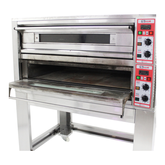
______________________________________________________________1. INTRODUCTION INTRODUCTION The electrically fed baking modules of the "CITIZEN" oven series have been designed mainly for the baking of pizzas and similar products in a traditional way. Of a high mechanical and electrical quality, the ovens of the "CITIZEN" series are built with a single frame, in a version with one or two chambers and with baking surfaces housing 6 or 9 pizzas having a 30 cm diameter. -
Page 6: How To Use This Manual
____________________________________________________2. HOW TO USE THIS MANUAL HOW TO USE THIS MANUAL The paragraphs with this symbol contain essential safety information. They must all be read both by the installers and by the final user and any of his staff who may use the equipment. The manufacturer shall not be held liable for any damage which may occur as a result of failure to observe the norms indicated in these paragraphs. - Page 7 ____________________________________________________2. HOW TO USE THIS MANUAL Chapter 4 provides all the information necessary for the installation of the equipment. The manual is primarily written for specialised staff but may be read in advance also by the final user to prepare and set up the space and plant necessary for the proper working of the equipment.
-
Page 8: Specifications
_____________________________________________________________3. SPECIFICATIONS SPECIFICATIONS 3.1 Product identification This manual refers to single chamber baking modules 6 - 9/MC and to double chamber modules 6+6 - 9+9/MC of Citizen series, version with electromechanical controls. 3.2 Conformity to directives The above mentioned baking modules carry the following compulsory marking: which guarantees their conformity to the following European directives: 2004/108/CE electromagnetic compatibility;... -
Page 9: Technical Specifications
_____________________________________________________________3. SPECIFICATIONS 3.4 Technical specifications The following table shows the baking modules’ technical specifications. Units of Citizen Citizen Citizen Citizen measure 6/MC 6+6/MC 9/MC 9+9/MC ment Weight 1370×960× 1370×960× 1370×1310× 1370×1310× External dimensions 1050×700× 1050×700× 1050×1050× 1050×1050× Cooking chamber size Capacity (pizzas Ø30cm) n°... -
Page 10: Installation
_______________________________________________________________4. INSTALLATION INSTALLATION ATTENTION: these installation instructions are for the exclusive use of personnel qualified for installation and maintenance of electrical and gas equipment conceived for professional use in the foodservice industry and community catering operations. An installation carried out by unqualified persons could cause damage to the oven, to people, animals or property. -
Page 11: Choosing A Place For Installation
_______________________________________________________________4. INSTALLATION 4.2 Choosing a place for installation An effective, safe and long lasting functioning of the appliance also depends on the position in which it is installed. For this reason, it is advisable to carefully consider where to install the equipment before it is delivered Install the appliance in a dry and easily accessible place both to facilitate its use and to carry out cleaning and maintenance. -
Page 12: Moving The Unit
(Fig.4.2 e Tab.4.1). Take care that children do not play with the packaging materials (e.g., plastic sheeting and Styrofoam): suffocation danger! a (mm) b (mm) c (mm) Citizen 6/MC Citizen 6+6/MC Citizen 9/MC Citizen 9+9/MC Table 4.1.Centre of gravity... -
Page 13: Mounting The Module
Position the modules one above the other in the right order (prover or base, baking module, hood) and fix by means of the accompanying hooks and screws. electrical cable input steam outlet a [mm] b [mm] c [mm] d [mm] w [mm] Citizen 6/MC 1370 Citizen 6+6/MC 1370 Citizen 9/MC 1083... -
Page 14: Emissions From Cooking Appliance
_______________________________________________________________4. INSTALLATION dispersion capacity as the appliance itself. The efficiency of this system must be correctly verified according to the norms in force. The power cable must terminate with a plug to connect to the electrical switchgear having a corresponding differential magneto thermal switch. The equipment is not supplied with a power plug. -
Page 15: Checking Before Starting Work
_______________________________________________________________4. INSTALLATION The manufacturer cannot answer for damage caused by ignoring these abovementioned norms as well as the information in this manual. Checking before starting work After completing installation of the unit a series of checks must be carried out, listed as follows: - check that the various disassembled parts have been assembled - check the power cable - check that the control panel is working... -
Page 16: Working
_________________________________________________________________5. WORKING WORKING 5.1 Control panel Figure 5.1. shows the control panel with all controls: 5.1.1 Temperature control (vers. TERM0012) Baking chamber temperature display Set button Push-button of ESC Up button Down button Out display 5.1.2 Temperature control (vers. TERM0060) Baking chamber temperature display Push-button set and ESC Up button... -
Page 17: Power Control
_________________________________________________________________5. WORKING 5.1.4 Power control Oven roof power regulator and light Oven bedplate power regulator and light. 5.2 Control description 5.2.1 Main ON/OFF switch When this switch is OFF, all displays on the control panel are off. When it is ON, the switch itself and the thermostat turn on, so that it is possible to set the temperature. -
Page 18: Set Button, Push-Button Of Esc (Vers. Term0012)
_________________________________________________________________5. WORKING 5.2.4 Temperature control Baking chamber temperature display In the normal operation mode, this display shows the cooking chamber temperature in °C. In the temperature programming mode, this display shows the programmed temperature. This displays is also used to display some failures (5.3). 5.2.5 Set button, Push-button of ESC (vers. -
Page 19: And Buttons
_________________________________________________________________5. WORKING To press a second time this push-button in order to exit from the way programming temperature. 5.2.7 buttons By pressing and releasing these buttons once, the set temperature increases or decreases by one unit. By keeping them pressed, the set temperature increases or decreases progressively, slowly at first and then faster. -
Page 20: Oven Roof And Bedplate Pilot Lamps
_________________________________________________________________5. WORKING for 15 seconds. When the power regulator is placed on 100, its heating element is always on (provided the display is on ). 5.2.11 Oven roof and bedplate pilot lamps Both oven roof and bedplate pilot lamps turn on when the display is on and its power regulator is switching on within the regulation cycle, to indicate that its heating element is actually on. -
Page 21: The Use Of The Oven
_______________________________________________________6. THE USE OF THE OVEN THE USE OF THE OVEN 6.1 Preparation for use If the equipment has just been installed or has not been used for a number of days, before using it for food products, it is necessary to clean it thoroughly in accordance with the indications in chapter 8 to remove residual factory dirt, accumulations of dust or any other substances which could contaminate food products. -
Page 22: General Indications For Good Cooking
_______________________________________________________6. THE USE OF THE OVEN 6.6 General indications for good cooking It is not possible to say exact times and temperatures for food products in general given the enormous variations they are subject to. As regards in particular pizzas and similar products, the cooking time and the temperature depend on the shape and thickness of the dough and the quantities of the ingredients added to it. -
Page 23: Cleaning
___________________________________________________________________7. CLEANING CLEANING At the end of each working day (or more frequently if possible) it is necessary to carefully clean the cooking surface and all the parts of the oven which come into contact with the food being cooked to avoid that any food substances go off and contaminate either the working environment or later products to be cooked. -
Page 24: Cleaning The Oven's Cooking Chamber
___________________________________________________________________7. CLEANING 7.3 Cleaning the oven's cooking chamber To clean the aluminum coated sheet steel cooking chamber, use a soft moistened sponge and if needs be a weak non abrasive detergent, making sure not to let any cleaning liquids drip onto the ceramic refractory material. If there is a consistent amount of fat deposited on the surfaces remove them first using a spatula. -
Page 25: Maintenance
______________________________________________________________8. MAINTENANCE MAINTENANCE WARNING: These use and maintenance instructions are intended only for staff which is qualified for the installation and maintenance of electrical and gas equipment. Maintenance by other persons may cause damage to the equipment, persons, animals or things. In the majority of cases it is necessary to remove the fixed guards in order to carry out repairs and checks;... -
Page 26: Electrical Diagram
8.3 Electrical diagram Pictures 10-1, 10-2, 10-3, 10-4, 10-5, 10-6, 10-7 show the wiring diagrams of the ovens Citizen 6/MC, 6+6/MC and Citizen 9/MC, 9+9/MC in the versions at 400Vac 3-N, 230Vac 3 and 230Vac 1-N. N.B. For double chamber ovens Citizen 6+6/MC and 9+9/MC, version... - Page 27 ______________________________________________________________8. MAINTENANCE Figure 10-1 Electrical diagram for Citizen 6/MC and 9/MC at 400 Vac 3N, 230 Vac. 3, 230 Vac. 1-N (auxiliary connection) ____________________________________________________________________________ CITIZEN 6 - 9/MC, CITIZEN 6+6 - 9+9/MC ELECTROMECHANICAL VERSION...
- Page 28 ______________________________________________________________8. MAINTENANCE Figure 10-2 Electrical diagram for Citizen 6/MC and 9/MC at 400 Vac 3N (power connection) ____________________________________________________________________________ CITIZEN 6 - 9/MC, CITIZEN 6+6 - 9+9/MC ELECTROMECHANICAL VERSION...
- Page 29 ______________________________________________________________8. MAINTENANCE Figure 10-3 Electrical diagram for Citizen 6/MC and 9/MC at 230 Vac 3 (power connection) ____________________________________________________________________________ CITIZEN 6 - 9/MC, CITIZEN 6+6 - 9+9/MC ELECTROMECHANICAL VERSION...
- Page 30 ______________________________________________________________8. MAINTENANCE Figure 10-4 Electrical diagram for Citizen 6/MC and 9/MC at 230 Vac 1N (power connection) ____________________________________________________________________________ CITIZEN 6 - 9/MC, CITIZEN 6+6 - 9+9/MC ELECTROMECHANICAL VERSION...
- Page 31 ______________________________________________________________8. MAINTENANCE Figure 10-5 Electrical diagram for Citizen 6+6/MC and 9+9/MC at 400 Vac 3N, 230 Vac. 3 (auxiliary connection) ____________________________________________________________________________ CITIZEN 6 - 9/MC, CITIZEN 6+6 - 9+9/MC ELECTROMECHANICAL VERSION...
- Page 32 ______________________________________________________________8. MAINTENANCE Figure 10-6 Electrical diagram for Citizen 6+6/MC and 9+9/MC at 400 Vac 3N (power connection) ____________________________________________________________________________ CITIZEN 6 - 9/MC, CITIZEN 6+6 - 9+9/MC ELECTROMECHANICAL VERSION...
- Page 33 ______________________________________________________________8. MAINTENANCE Figure 10-7 Electrical diagram for Citizen 6+6/MC and 9+9/MC at 230 Vac 3 (power connection) N.B. For the version at 230Vac 1-N of the double chamber ovens Citizen 6+6/MC and 9+9/MC, see chapter 8.3 and wiring diagrams Pic.10-1, 10-4. ____________________________________________________________________________ CITIZEN 6 - 9/MC, CITIZEN 6+6 - 9+9/MC ELECTROMECHANICAL VERSION...
-
Page 34: Exploded Views And Spare Parts List
The parts drawing of Pict. 10-8 refers to the double chamber modules of Citizen 6+6/MC and 9+9/MC, but the references are also valid for single chamber modules of Citizen 6/MC and 9/MC. ____________________________________________________________________________ CITIZEN 6 - 9/MC, CITIZEN 6+6 - 9+9/MC ELECTROMECHANICAL VERSION... - Page 35 ______________________________________________________________8. MAINTENANCE Codes N° Description Citizen Citizen Citizen Citizen 6/MC 6+6/MC 9/MC 9+9/MC GLASS RESTRAINING CARP0111 CARP0111 CARP0111 CARP0111 FRAME LEFT STIRRUP SUPP0392 SUPP0392 SUPP0392 SUPP0392 DOOR FRAME PORT0202 PORT0202 PORT0202 PORT0202 RIGHT STIRRUP SUPP0391 SUPP0391 SUPP0391 SUPP0391 RESISTANCE FRONT RESI0077 RESI0077 RESI0077...
- Page 36 ______________________________________________________________8. MAINTENANCE Figure 10-8 Exploded view ____________________________________________________________________________ CITIZEN 6 - 9/MC, CITIZEN 6+6 - 9+9/MC ELECTROMECHANICAL VERSION...
- Page 37 ______________________________________________________________8. MAINTENANCE Codes N° Description Citizen Citizen 6/MC, 6+6/MC 9/MC, 9+9/MC TERM0012 TERM0012 THERMOREGULATION DIGITAL TERM0060 TERM0060 PROBE TERM0020 TERM0020 ELET0432 ELET0432 CONTROL SWITCH 32A ELET0160 ELET0160 ELET0002 ELET0002 FUSE PORTGRAY 16 MMQ or ELET0438 ELET0438 FUSE PORTGRAY 35 MMQ ELET0049 ELET0049 ELET0439...
- Page 38 ______________________________________________________________8. MAINTENANCE Figure 10-9 Exploded view of electrical parts ____________________________________________________________________________ CITIZEN 6 - 9/MC, CITIZEN 6+6 - 9+9/MC ELECTROMECHANICAL VERSION...
-
Page 39: Decommissioning And Demolition
__________________________________________9. DECOMMISSIONING AND DEMOLITION DECOMMISSIONING AND DEMOLITION Before decommissioning, disconnect the electrical supply and any other connections before proceeding to move the unit by a suitable means such as a forklift truck, hoist, etc. The ovens are composed of the following materials: stainless steel, varnished sheet steel, aluminum coated sheet steel, glass, ceramic material, rock wool and electrical parts. -
Page 40: Declaration Of Conformity
_______________________________________________10. DECLARATION OF CONFORMITY 10. DECLARATION OF CONFORMITY ____________________________________________________________________________ CITIZEN 6 - 9/MC, CITIZEN 6+6 - 9+9/MC ELECTROMECHANICAL VERSION...
Need help?
Do you have a question about the CITIZEN 6/MC and is the answer not in the manual?
Questions and answers