
Related Manuals for ZANOLLI CITIZEN 6-9 GAS PW


Summary of Contents for ZANOLLI CITIZEN 6-9 GAS PW
- Page 1 D I A G R A M S T E C H N I C A L CITIZEN 6-9 GAS PW 0 1 7 0 6 3 5 3 6 3 3 W W W . F O O D S E R V I C E S P A R E S . C O M...
- Page 2 DR. ZANOLLI s.r.l. Via Casa Quindici, 22 37060 Caselle di Sommacampagna (Verona) Italy Tel +39 045 8581500 (r.a.) Fax +39 045 8581455 Web: www.zanolli.it · e-mail: zanolli@zanolli.it CITIZEN 6-9 GAS PW Pizza Oven Manual for installation use and maintenance...
- Page 3 Casa Quindici 22 37060 Caselle di Sommacampagna VR Tel. +39-0458581500 Fax +39-0458581455 VAT N.IT00213620230 Citizen 6-9 gas PW English Manual cod. CITG.G.EM.PW.UK.09 rev. 0.0 del 15/02/11...
- Page 4 INDEX INDEX 1. INTRODUCTION ..............5 2. HOW TO USE THIS MANUAL ..........6 3. SPECIFICATIONS ..............8 IDENTIFYING THE PRODUCT ............8 HESE INSTRUCTIONS REFER TO THE ITIZEN GAS ITIZEN GAS COOKING ......................8 UNITS CONFORMITY TO EUROPEAN DIRECTIVES .......8 INTENDED OPERATING CONDITIONS .........8 TECHNICAL SPECIFICATIONS .............8 4.
- Page 5 INDEX 5.1.7 ON/OFF KNOB FOR PILOT LIGHT AND BURNER ....21 5.1.8 PILOT LIGHT IGNITION SWITCH ..........21 ERROR INDICATION ..............22 5.2.1 Disconnected thermocouple (vers. TERM0012) ........22 5.2.2 Disconnected thermocouple (vers. TERM0060) ........22 LACK OF GAS OR ELECTRICITY SUPPLY ........22 6.
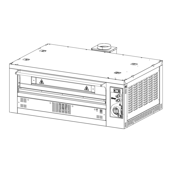
- Page 6 INTRODUCTION 1. INTRODUCTION The gas fired cooking units for the CITIZEN oven series have been primarily designed for cooking pizzas and similar products in the traditional way. As part of the modular CITIZEN system they can be coupled together with other elements in the series (hood, baking chamber, basic unit) serving client’s specific requirements.
-
Page 7: How To Use This Manual
HOW TO USE THIS MANUAL 2. HOW TO USE THIS MANUAL The paragraphs marked with this symbol contain indications essential to safety, operating instructions and maintenance. They must all be read both by installers, the end user and any employees that use the oven. - Page 8 HOW TO USE THIS MANUAL Chapter 3 contains the specifications of the oven and all the values that are necessary for choosing the right environment for its installation and use. This manual should be used as a point of reference to check that the equipment is being used in the way intended and ensure that information concerning the precise value of a given measurement or tolerance of the equipment is available whenever necessary.
-
Page 9: Specifications
SPECIFICATIONS 3. SPECIFICATIONS 3.1 IDENTIFYING THE PRODUCT These instructions refer to the Citizen gas 6 and Citizen gas 9 cooking units. 3.2 CONFORMITY TO EUROPEAN DIRECTIVES Both the Citizen gas 6 and Citizen gas 9 cooking units bear the following obligatory markings showing their conformity to the following European directives 2004/108/CE electromagnetic compatibility;... - Page 10 SPECIFICATIONS Unità Citizen 6 GAS Citizen 9 GAS di misura Weight External dimensions 1450x1090x560 1450x1440x560 Chamber dimensions 1050x700x160 1050x1050x160 13.5 (n°45 pizze/h (n°54 pizze/h Kg/h Hourly Production da 300 gr.) da 300 gr.) Single phase Electricity supply Voltage Frequency 50 o 60 Current at 230 V 50 Hz Total electrical power Electric connection...
- Page 11 SPECIFICATIONS measurement Maximum temperature °C setting Flame intensity regulation Error indication in display Ambient conditions Temperature 0 - 40 °C Maximum humidity 95% without condensation Predisposed for 20 mbar Table 3-1 Technical specifications CITIZEN 6 - 9 GAS PW...
-
Page 12: Installation
INSTALLATION 4. INSTALLATION ATTENTION: these installation instructions are for the exclusive use of personnel qualified for the installation and maintenance of gas appliances. An installation carried out by unqualified persons could cause damage to the oven, to people, animals or property. ATTENTION: Proceed with the installation according to those norms in force in the country in which it is carried out. - Page 13 INSTALLATION 4.2 CHOOSING A PLACE FOR INSTALLATION An effective, safe and long lasting functioning of the appliance also depends on the position in which it is installed. For this reason, it is advisable to carefully consider where to install the equipment before it is delivered Install the appliance in a dry and easily accessible place both to facilitate its use and to carry out cleaning and maintenance.
-
Page 14: Connecting The Gas Supply
INSTALLATION threaded through the rings on the top of the oven and lift with a fork lift truck (Fig.1). DO NOT raise the module by inserting forks or bars inside the cooking chambrer because this could cause damage the refractory material at the top of the oven 4.4 POSITIONING AND MOUNTING THE MODULE... -
Page 15: Electrical Connection
INSTALLATION The connection of the tubing to the equipment must be made with a three piece metal joint to facilitate disassembly The strength of the gas tight holding on the threaded joint must be ensured with materials specifically declared to be suitable by their manufacturer also for GPL gasses. - Page 16 INSTALLATION For the positions of the electrical input connectors, see Fig. 4-1 The manufacturer does not accept responsibility for damage caused by failure to observe the abovementioned norms. A= ELECTRICAL POWER INPUT B= GAS SUPPLY INPUT C= EXHAUST COMBUSTION FUMES Ø 150mm (MODULE WITHOUT HOOD) D= VAPOUR EXHAUST Ø...
-
Page 17: Checking Before Use
INSTALLATION 4.7 CHECKING BEFORE USE 1 - Check the electrical cabling 2 - Check the gastight integrity of tubing for the gas supply and other tubing for the exhaust gasses 3 - Check that the control panel is in working order 4 - Check the rated current of the working oven at the solenoid valve termination CITIZEN 6 - 9 GAS PW... -
Page 18: Operating The Oven
OPERATING 5. OPERATING THE OVEN 5.1 DESCRIPTION OF THE CONTROL PANEL Temperature control (vers. TERM0012) Chamber temperature Display Set button ESC button Up button Down button Out indicator Temperature control (vers. TERM0060) Chamber temperature display Set and ESC button Up Button Down button "out1"Green led indicator light “out1”... - Page 19 OPERATING Ignition/out knob for pilot light and burner Luminous red button for igniting pilot light 5.1.1 DIGITAL THERMO-REGULATOR (VERS. TERM0 012) In temperature programming mode, this display shows the programmed temperature. The light next to it goes off signaling that the temperature has been reached.
- Page 20 OPERATING Out indicator (vers. TERM0012) indicator illuminates whenever the temperature of the chamber is lower than that set. It goes out when the temperature of the chamber reaches that set and it turns on again when the temperature of the chamber falls by 1 °C below the set temperature.
-
Page 21: Master Switch
OPERATING "out1" Green led indicator (vers. TERM0060) The green led indicator illuminates whenever the temperature of the chamber is lower than that set. It goes out when the temperature of the chamber reaches that set and it turns on again when the temperature of the chamber falls by 1 °C below the set temperature. - Page 22 OPERATING 5.1.7 ON/OFF KNOB FOR PILOT LIGHT AND BURNER This knob is for igniting the pilot light and the burner. To open the flow of gas for the ignition of the pilot light, keep the knob pressed in and turn it anticlockwise until the first step. To bring the intensity of the burner flame to “maximum”, keep the knob pressed in and turn it anticlockwise until the second step.
-
Page 23: Error Indication
OPERATING 5.2 ERROR INDICATION The electronic digital thermo-regulator can signal abnormal functioning as described in the paragraphs below. 5.2.1 Disconnected thermocouple (vers. TERM0012) When the thermocouple is disconnected or interrupted, the display shows “E1”. 5.2.2 Disconnected thermocouple (vers. TERM0060) When the thermocouple is disconnected or interrupted, the display shows “E1”. -
Page 24: Turning On For The First Time
6. USE 6.1 TURNING ON FOR THE FIRST TIME Before connecting the electricity supply to the oven, ensure that the master switch is in the “0” position Ensure the effectiveness of the gas connections, then open the tap to the fixed gas supply. IMPORTANT –... - Page 25 press the knob and rotate it once again, as far as it will go, in an anticlockwise direction. It is possible to check whether the burner is lit as indicted by the green light or by observing the flame through the four holes in the front panel of the burner.
- Page 26 6.4 HOW TO TURN OFF THE OVEN To turn off the oven, turn the knob in a clockwise direction to the OFF position, put the master switch in the “0” position and close the tap on the fixed gas supply conduit. N.b.
- Page 27 6.6 WHEN THE OVEN IS UNDERUSED When there are no products to bake, set the oven to a temperature of 250°C and bring the intensity of the burner flame down to a minimum. This ensures a saving on the consumption of gas. CITIZEN 6 - 9 GAS PW...
- Page 28 CLEANING 7. CLEANING At the end of each working day (if not more often) it is necessary to carefully clean the oven and all the parts that have come in contact with cooked products. This is to avoid food substances causing deterioration and polluting both the working area and products that are subsequently cooked.
-
Page 29: Cleaning External Surfaces
CLEANING 7.3 CLEANING THE OVEN’S COOKING CHAMBER To clean the stainless steel or aluminium coated sheet steel cooking chamber, use a soft moistened sponge and if needs be a weak non abrasive detergent. If there is a consistent amount of fat deposited on the surfaces remove them first using a spatula. -
Page 30: Changing The Halogen Lamp
MAINTAINANCE 8. MAINTAINANCE ATTENTION: these maintenance instructions are to be used exclusively by personnel qualified to install and maintain electrical and gas appliances. Maintenance work carried out by non qualified personnel could cause damage to the oven, to persons, animals or property. To carry out repairs and routine checks it will be necessary, in most cases, to remove the safety panel. -
Page 31: Safety Thermostat
MAINTAINANCE 3 - Unscrew the 2 screws that fix the lamp to its holder using a flat headed screwdriver and pull it out, substituting the lamp with one of the same type. 8.2 SAFETY THERMOSTAT The safety thermostat intervenes when the temperature of the baking chamber has exceeded 500°C closing off the gas supply valve. - Page 32 MAINTAINANCE Fig. 8-1 Wiring diagram CITIZEN 6 - 9 gas at 230Vac 1-N 50/60 Hz CITIZEN 6 - 9 GAS PW...
- Page 33 MAINTAINANCE 8.4 ADAPTATION TO VARIOUS TYPES OF GAS Attention! To adapt the cooking unit for use with a different type of gas from that indicated on the initial setting label, it is necessary to carry out the steps described in the following paragraphs: Carefully carry out all the steps shown below.
- Page 34 MAINTAINANCE 3 – Unthread the jet with a number 12 spanner and replace it with one foreseen for the new supply 4 – Regulate the air intake according to the table (tab. 8-1) and undo the nut with a number 8 spanner. 5 - Unscrew the pilot light screw with a flat headed screwdriver and replace the pilot light jet with one foreseen for...
- Page 35 MAINTAINANCE 6 - Check if there are any gas leaks from the system. Take off the oven’s side panel to access the area of the solenoid and electrical system. Light the oven and set the flame intensity to “maximum”. Connect a manometer to the pressure testing socket A and verify the correct entry pressure to the solenoid valve (see table 8-1).
- Page 36 MAINTAINANCE Unit of Citizen 6 GAS Citizen 9 GAS measure Burner jet diameter according to [gas type] and pressure G20 - 20 mbar 3.15 G25 - 20 mbar 3.15 G25 - 25 mbar 3.15 G30 - 28..30 mbar 2.25 G31 - 30..37 mbar G30 - 50 mbar 2.25 G31 - 50 mbar...
- Page 37 MAINTAINANCE 8.4.2 Applying the new label Remove the old label and carefully clean the area using a cloth dampened with petrol. Stick on the label showing the type and pressure of gas that the unit has been adapted to (the label, together with jet and instructions for the modification are contained in the modification kit supplied on request for each type and pressure of gas).
- Page 38 MAINTAINANCE CITIZEN 6 - 9 GAS PW...
- Page 39 MAINTAINANCE 8.6 EXPLODED DIAGRAMS AND LIST OF REPLACEMENT PARTS For more complex interventions and in the event of breakdowns please contact us. However to make it easier to find the cause of the problem and replace broken parts here is a list of spare parts and exploded drawings of the oven with reference to each listed part.
- Page 40 MAINTAINANCE TABELLA CODICI DI RIFERIMENTO POS DENOMINAZIONE CODICE CODICE Citizen 6 gas Citizen 9 gas External door PORT0353 PORT0353 Glass holder PORT0319 PORT0319 Left plate SUPP0206 SUPP0206 Tubing handle MANI0063 MANI0063 Bush BOCC0006 BOCC0006 Internal door PORT0352 PORT0352 Door frame PORT0350 PORT0350 Left side panel...
- Page 41 MAINTAINANCE FIG. 8-2 Exploded view CITIZEN 6 - 9 GAS PW...
- Page 42 MAINTAINANCE CITIZEN 6-9 GAS ELECTRICAL COMPONENTS INTE0020 Black I-0-II switch PANN0327 Adhesive membrane TERM0012 / TERM0060 Digital Thermoregulator INTE0010 Luminous green bip. switch 0-1 INTE0009 Luminous yellow bip. switch 0-1 LAMP0007 Round green indicator light GASI0086 Gas tap knob INTE0012 Red bip "0"...
- Page 43 MAINTAINANCE AGAS0034 Solenoid gas valve AGAS0035 Gas tap TERM0064 Pilot light thermocouple AGAS0009 Pilot light ignition electrode UGAS0046 Pilot jet AGAS0010 Pilot light tap CITIZEN 6 - 9 GAS PW...
- Page 44 MAINTAINANCE LAMP0021 Two pronged lampo holder LAMP0020 Halogen lamp CITIZEN 6 - 9 GAS PW...
-
Page 45: Decomissioning And Demolition
DECOMISSIONING AND DEMOLITION 9. DECOMISSIONING AND DEMOLITION Before decommissioning, disconnect the electrical supply and any other connections before proceeding to move the unit by a suitable means such as a forklift truck, hoist, etc. The ovens are composed of the following materials: stainless steel, varnished sheet steel, aluminum coated sheet steel, glass, ceramic material, rock wool and electrical parts. - Page 46 FOODSERVICE EQUIPMENT SPARES LTD UNIT 4 SANDBROOK PARK, SANDBROOK WAY, ROCHDALE, OL11 1RY 01706 353 633 SALES@FOODSERVICESPARES.COM W W W . F O O D S E R V I C E S P A R E S . C O M...
Need help?
Do you have a question about the CITIZEN 6-9 GAS PW and is the answer not in the manual?
Questions and answers