Table of Contents
Advertisement
DR. ZANOLLI s.r.l.
Via Casa Quindici, 22
37066 Caselle di Sommacampagna (Verona) Italy
Tel +39 045 8581500 (r.a.)
Fax +39 045 8581455
Web: www.zanolli.it • e-mail: zanolli@zanolli.it
CITIZEN 6 - 9/MC
CITIZEN 6+6 - 9+9/MC
DIGITAL VERSION
Pizza and delicatessen ovens
Installation, use and maintenance manual
Advertisement
Table of Contents

Related Manuals for ZANOLLI CITIZEN Series


Summary of Contents for ZANOLLI CITIZEN Series
- Page 1 DR. ZANOLLI s.r.l. Via Casa Quindici, 22 37066 Caselle di Sommacampagna (Verona) Italy Tel +39 045 8581500 (r.a.) Fax +39 045 8581455 Web: www.zanolli.it • e-mail: zanolli@zanolli.it CITIZEN 6 - 9/MC CITIZEN 6+6 - 9+9/MC DIGITAL VERSION Pizza and delicatessen ovens...
- Page 2 Casa Quindici 22 37066 Caselle di Sommacampagna VR TEL. +39-0458581500 FAX +39-0458581455 VAT N.IT00213620230 Citizen 6 - 9/MC, Citizen 6+6 - 9+9/MC Digital version English manual cod. CIT.M-B.E.D.UK.12 rev. 0.0 del 21/02/2012...
-
Page 3: Table Of Contents
_________________________________________________________________________INDEX INDEX 1. INTRODUCTION................5 2. HOW TO USE THIS MANUAL ..........6 3. SPECIFICATIONS ..............8 3.1 Product identification............... 8 3.2 Conformity to directives ..............8 3.3 Envisaged use................... 8 3.4 Technical specifications ..............9 4. INSTALLATION ...............10 4.1 Checking on delivery..............10 4.2 Choosing a place for installation .......... - Page 4 _________________________________________________________________________INDEX 5.4.4 Timer setting....................22 5.5 Alarms ..................... 22 5.5.1 Overtemperature alarm ................22 6. THE USE OF THE OVEN ............23 6.1 Preparation for use................. 23 6.2 Ignition of the control panel ............23 6.3 Settings.................... 23 6.4 Baking start ..................23 6.5 Loading the oven ................
-
Page 5: Introduction
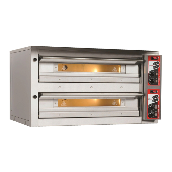
______________________________________________________________1. INTRODUCTION INTRODUCTION The electrically fed baking modules of the "CITIZEN" oven series have been designed mainly for the baking of pizzas and similar products in a traditional way. Of a high mechanical and electrical quality, the ovens of the "CITIZEN" series are built with a single frame, in a version with one or two chambers and with baking surfaces housing 6 or 9 pizzas having a 30 cm diameter. -
Page 6: How To Use This Manual
____________________________________________________2. HOW TO USE THIS MANUAL HOW TO USE THIS MANUAL The paragraphs with this symbol contain essential safety information. They must all be read both by the installers and by the final user and any of his staff who may use the equipment. The manufacturer shall not be held liable for any damage which may occur as a result of failure to observe the norms indicated in these paragraphs. - Page 7 ____________________________________________________2. HOW TO USE THIS MANUAL Chapter 4 provides all the information necessary for the installation of the equipment. The manual is primarily written for specialised staff but may be read in advance also by the final user to prepare and set up the space and plant necessary for the proper working of the equipment.
-
Page 8: Specifications
2006/95/CE low voltage. 3.3 Envisaged use The baking modules of the Citizen series have been designed to bake pizzas and similar products and non fine pastry onto pans or directly on refractory surfaces. Such modules are meant for a professional use only by qualified personnel in the restaurant industry (restaurants, pizzerias, pastry shops, etc.) and are exclusively intended to be used by qualified staff. -
Page 9: Technical Specifications
_____________________________________________________________3. SPECIFICATIONS 3.4 Technical specifications The following table shows the baking modules’ technical specifications. Units of Citizen Citizen Citizen Citizen measure 6/MC 6+6/MC 9/MC 9+9/MC ment Weight 1370×960× 1370×960× 1370×1310× 1370×1310× External dimensions 1050×700× 1050×700× 1050×1050× 1050×1050× Cooking chamber size Capacity (pizzas Ø30cm) n°... -
Page 10: Installation
_______________________________________________________________4. INSTALLATION INSTALLATION ATTENTION: these installation instructions are for the exclusive personnel qualified installation maintenance of electrical and gas equipment conceived for professional use in the foodservice industry and community catering operations. An installation carried out by unqualified persons could cause damage to the oven, to people, animals or property. -
Page 11: Choosing A Place For Installation
_______________________________________________________________4. INSTALLATION 4.2 Choosing a place for installation An effective, safe and long lasting functioning of the appliance also depends on the position in which it is installed. For this reason, it is advisable to carefully consider where to install the equipment before it is delivered Install the appliance in a dry and easily accessible place both to facilitate its use and to carry out cleaning and maintenance. -
Page 12: Moving The Unit
_______________________________________________________________4. INSTALLATION 4.3 Moving the unit To offload and transport the unit, use a pallet truck or a transpallet lifter with a load capacity at least equal to that of the unit, insert the forks into the space provided in the lower part of the packing. When moving the module which is not packed insert the forks in the upper chamber. -
Page 13: Mounting The Module
_______________________________________________________________4. INSTALLATION 4.4 Mounting the module Position the modules one above the other in the right order (prover or base, baking module, hood) and fix by means of the accompanying hooks and screws. electrical cable input steam outlet a [mm] b [mm] c [mm] d [mm] w [mm] Citizen 6/MC 1370 Citizen 6+6/MC... -
Page 14: Emissions From Cooking Appliance
_______________________________________________________________4. INSTALLATION dispersion capacity as the appliance itself. The efficiency of this system must be correctly verified according to the norms in force. The power cable must terminate with a plug to connect to the electrical switchgear having a corresponding differential magneto thermal switch. The equipment is not supplied with a power plug. -
Page 15: Checking Before Starting Work
_______________________________________________________________4. INSTALLATION The manufacturer cannot answer for damage caused by ignoring these abovementioned norms as well as the information in this manual. Checking before starting work After completing installation of the unit a series of checks must be carried out, listed as follows: - check that the various disassembled parts have been assembled - check the power cable... -
Page 16: Working
_________________________________________________________________5. WORKING WORKING 5.1 Description of controls Fig. 6.1 shows the control panel with all controls: General system on/off button Oven temperature and time display Set temperature display Program setting increase button “Timer” - “Oven temperature” – Clock setting” display button - Program setting decrease button Upper element power setting... -
Page 17: System Functional States
_________________________________________________________________5. WORKING 5.2 System functional states 5.2.1 Standby on/off button When on standby the panel is powered but no system function is enabled. The general remote switch is disabled and the message OFF is displayed on the set display on the control panel along with the current time on the display with flashing seconds dot (between the second and third figure, ½... -
Page 18: Economy Button
_________________________________________________________________5. WORKING Note that with this setting, for the first 20 seconds only the upper elements are on, so the oven uses half the total power. Over the next 10 seconds both the upper and power elements are on, with the oven using full power. In the remaining 15 seconds, on the lower elements are on, so the oven once again uses half its available power. -
Page 19: Switch For Suction Hood
_________________________________________________________________5. WORKING 5.3.6 Switch for suction hood The switch for suction hood control is placed on the side part of the control panel, on the upper side (Pos.1 of Fig. 6.2). Pos.1 Push this switch on position “I” to start one of the two motors of the suction hood. -
Page 20: Baking Cycle Programming
_________________________________________________________________5. WORKING Press again to memorise the new time and day. When set, the dot between hours and minutes begins to flash and the day display disappears. 5.4.2 Baking cycle programming To program the baking cycle the oven must be on. Press the general system on/off button . -
Page 21: Auto Switch-On Programming
_________________________________________________________________5. WORKING If the Set temperature is to be modified the button should be pressed top display the relative value on the display. It can be modified by means of the buttons. Once the required values have been set, the can be memorised by pressing the button, and the panel returns to its enabled state. -
Page 22: Timer Setting
_________________________________________________________________5. WORKING Pressing again memorises the time and day of the week on which the oven will automatically switch on. Once set and memorised, the returns to displaying the current time and the dot between the hours and minutes flashes. The dot following the minute display remains lit indicating that a time has been set for automatic switch-on. -
Page 23: The Use Of The Oven
_______________________________________________________6. THE USE OF THE OVEN THE USE OF THE OVEN 6.1 Preparation for use If the equipment has just been installed or has not been used for a number of days, before using it for food products, it is necessary to clean it thoroughly in accordance with the indications in chapter 8 to remove residual factory dirt, accumulations of dust or any other substances which could contaminate food products. -
Page 24: General Indications For Good Cooking
_______________________________________________________6. THE USE OF THE OVEN 6.6 General indications for good cooking It is not possible to say exact times and temperatures for food products in general given the enormous variations they are subject to. As regards in particular pizzas and similar products, the cooking time and the temperature depend on the shape and thickness of the dough and the quantities of the ingredients added to it. - Page 25 _______________________________________________________6. THE USE OF THE OVEN During long periods of idleness (e.g. closures for holidays) it is advisable to switch off the main switch on the electrical feed panel. ____________________________________________________________________________ CITIZEN 6 - 9/MC, CITIZEN 6+6 - 9+9/MC DIGITAL VERSION...
-
Page 26: Cleaning
___________________________________________________________________7. CLEANING CLEANING At the end of each working day (or more frequently if possible) it is necessary to carefully clean the cooking surface and all the parts of the oven which come into contact with the food being cooked to avoid that any food substances go off and contaminate either the working environment or later products to be cooked. -
Page 27: Cleaning The Oven's Cooking Chamber
___________________________________________________________________7. CLEANING 7.3 Cleaning the oven's cooking chamber To clean the aluminum coated sheet steel cooking chamber, use a soft moistened sponge and if needs be a weak non abrasive detergent, making sure not to let any cleaning liquids drip onto the ceramic refractory material. If there is a consistent amount of fat deposited on the surfaces remove them first using a spatula. -
Page 28: Maintenance
______________________________________________________________8. MAINTENANCE MAINTENANCE WARNING: These use and maintenance instructions are intended only for staff which is qualified for the installation and maintenance of electrical and gas equipment. Maintenance by other persons may cause damage to the equipment, persons, animals or things. In the majority of cases it is necessary to remove the fixed guards in order to carry out repairs and checks;... -
Page 29: Electrical Diagram
______________________________________________________________8. MAINTENANCE 8.3 Electrical diagram Pictures 10-1, 10-2, 10-3, 10-4, 10-5, 10-6, 10-7 show the wiring diagrams of the ovens Citizen 6/MC, 6+6/MC and Citizen 9/MC, 9+9/MC in the versions at 400Vac 3-N, 230Vac 3 and 230Vac 1-N. N.B. For double chamber ovens Citizen 6+6/MC and 9+9/MC, version 230Vac 1-N, due to the high total electrical absorption, you have to handle each single chamber as one-chamber ovens, each with separate electrical supply. - Page 30 ______________________________________________________________8. MAINTENANCE Figure 10-1 Electrical diagram for Citizen 6/MC and 9/MC at 400 Vac 3N, 230 Vac. 3, 230 Vac. 1-N (auxiliary connection) ____________________________________________________________________________ CITIZEN 6 - 9/MC, CITIZEN 6+6 - 9+9/MC DIGITAL VERSION...
- Page 31 ______________________________________________________________8. MAINTENANCE Figure 10-2 Electrical diagram for Citizen 6/MC and 9/MC at 400 Vac 3N (power connection) ____________________________________________________________________________ CITIZEN 6 - 9/MC, CITIZEN 6+6 - 9+9/MC DIGITAL VERSION...
- Page 32 ______________________________________________________________8. MAINTENANCE Figure 10-3 Electrical diagram for Citizen 6/MC and 9/MC at 230 Vac 3 (power connection) ____________________________________________________________________________ CITIZEN 6 - 9/MC, CITIZEN 6+6 - 9+9/MC DIGITAL VERSION...
- Page 33 ______________________________________________________________8. MAINTENANCE Figure 10-4 Electrical diagram for Citizen 6/MC and 9/MC at 230 Vac 1N (power connection) ____________________________________________________________________________ CITIZEN 6 - 9/MC, CITIZEN 6+6 - 9+9/MC DIGITAL VERSION...
- Page 34 ______________________________________________________________8. MAINTENANCE Figure 10-5 Electrical diagram for Citizen 6+6/MC and 9+9/MC at 400 Vac 3N, 230 Vac. 3 (auxiliary connection) ____________________________________________________________________________ CITIZEN 6 - 9/MC, CITIZEN 6+6 - 9+9/MC DIGITAL VERSION...
- Page 35 ______________________________________________________________8. MAINTENANCE Figure 10-6 Electrical diagram for Citizen 6+6/MC and 9+9/MC at 400 Vac 3N (power connection) ____________________________________________________________________________ CITIZEN 6 - 9/MC, CITIZEN 6+6 - 9+9/MC DIGITAL VERSION...
- Page 36 ______________________________________________________________8. MAINTENANCE Figure 10-7 Electrical diagram for Citizen 6+6/MC and 9+9/MC at 230 Vac 3 (power connection) N.B. For the version at 230Vac 1-N of the double chamber ovens Citizen 6+6/MC and 9+9/MC, see chapter 8.3 and wiring diagrams Pic.10-1, 10-4. ____________________________________________________________________________ CITIZEN 6 - 9/MC, CITIZEN 6+6 - 9+9/MC DIGITAL VERSION...
-
Page 37: Exploded Views And Spare Parts List
______________________________________________________________8. MAINTENANCE 8.5 Exploded views and spare parts list In order to make the troubleshooting and the request for the parts to replace the damaged ones easier, we are giving you hereunder a list of the main spare parts and parts drawing with references to the single parts listed. For more complex interventions and in the event of breakdowns please contact us. - Page 38 ______________________________________________________________8. MAINTENANCE Codes N° Description Citizen Citizen Citizen Citizen 6/MC 6+6/MC 9/MC 9+9/MC GLASS RESTRAINING CARP0111 CARP0111 CARP0111 CARP0111 FRAME LEFT STIRRUP SUPP0206 SUPP0206 SUPP0206 SUPP0206 DOOR FRAME PORT0202 PORT0202 PORT0202 PORT0202 RIGHT STIRRUP SUPP0207 SUPP0207 SUPP0207 SUPP0207 RESISTANCE FRONT RESI0077 RESI0077 RESI0077...
- Page 39 ______________________________________________________________8. MAINTENANCE Figure 10-8 Exploded view ____________________________________________________________________________ CITIZEN 6 - 9/MC, CITIZEN 6+6 - 9+9/MC DIGITAL VERSION...
- Page 40 ______________________________________________________________8. MAINTENANCE Codes N° Description Citizen Citizen 6/MC, 6+6/MC 9/MC, 9+9/MC PROBE TERM0020 TERM0020 ELET0432 ELET0432 CONTROL SWITCH 32A ELET0160 ELET0160 ELET0002 ELET0002 FUSE PORTGRAY 16 MMQ or ELET0438 ELET0438 FUSE PORTGRAY 35 MMQ ELET0049 ELET0049 EARTH PORT 16 MMQ or ELET0439 ELET0439 EARTH PORT 35 MMQ...
- Page 41 ______________________________________________________________8. MAINTENANCE Figure 10-9 Exploded view of electrical parts ____________________________________________________________________________ CITIZEN 6 - 9/MC, CITIZEN 6+6 - 9+9/MC DIGITAL VERSION...
-
Page 42: Decommissioning And Demolition
__________________________________________9. DECOMMISSIONING AND DEMOLITION DECOMMISSIONING AND DEMOLITION Before decommissioning, disconnect the electrical supply and any other connections before proceeding to move the unit by a suitable means such as a forklift truck, hoist, etc. The ovens are composed of the following materials: stainless steel, varnished sheet steel, aluminum coated sheet steel, glass, ceramic material, rock wool and electrical parts. -
Page 43: Declaration Of Conformity
_______________________________________________10. DECLARATION OF CONFORMITY 10. DECLARATION OF CONFORMITY ____________________________________________________________________________ CITIZEN 6 - 9/MC, CITIZEN 6+6 - 9+9/MC DIGITAL VERSION...
Need help?
Do you have a question about the CITIZEN Series and is the answer not in the manual?
Questions and answers