Table of Contents
Advertisement
Advertisement
Table of Contents

Related Manuals for ZANOLLI CITIZEN EP 70/4+4


Summary of Contents for ZANOLLI CITIZEN EP 70/4+4
- Page 1 CITIZEN EP 70 Manuale di installazione, uso e manutenzione Manual for installation, use and maintenance Manual de instalación, uso y manutención Notice d’installation, d’utilisation et d’entretien -, B NSTALLATIONS EDIENUNGS NSTANDHALTUNGSHANDBUCH...
-
Page 3: Table Of Contents
cod. CITEP70.M-B.E.EM.UK.14 - rev. 0.4 del 26/02/19 INDEX 1. INTRODUCTION ..................5 2. HOW TO USE THIS MANUAL ..............6 3. TECHNICAL SPECIFICATIONS ..............8 Product identification ..............8 Conformity to directives ............8 Envisaged use ................8 Technical specifications ............9 4. - Page 4 cod. CITEP70.M-B.E.EM.UK.14 - rev. 0.4 del 26/02/19 Cleaning the oven’s baking chamber ........20 Cleaning the external surface ..........21 8. MAINTENANCE ..................22 Ordinary maintenance work ........... 22 8.1.1 Light replacement ..............22 Safety thermostat ..............23 Electrical diagram ..............24 Adjustment for different feed voltages ........
-
Page 5: Introduction
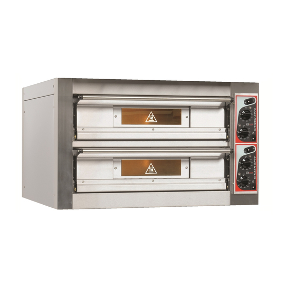
1. INTRODUCTION 1. INTRODUCTION The modular “CITIZEN EP70” oven represent the new way to make traditional ovens used for “fast food”. They are designed and manufactured to demanding mechanical and electrical standards and are built to last. Made out of stainless steel and the baking surfaces is in a special refractory material to enable a proper diffusion of the heat. -
Page 6: How To Use This Manual
2. HOW TO USE THIS MANUAL 2. HOW TO USE THIS MANUAL This manual should be kept near to the equipment itself so it can be quickly and easily consulted. The manual must travel with the equipment if it is moved to another owner as the latter may not be considered complete or safe without it. - Page 7 2. HOW TO USE THIS MANUAL Chapter 5 is for reference whenever the user wishes to clarify specific aspects of the equipment operation. It is not advisable to use these chapters as a way to learn how to use the equipment. Chapter 6 is useful for the user who has to learn to use the oven from scratch.
-
Page 8: Technical Specifications
3. TECHNICAL SPECIFICATIONS 3. TECHNICAL SPECIFICATIONS Product identification This manual refers to the electric single-chamber and twin-chamber oven mod. CITIZEN EP70. Conformity to directives The electric oven mod. CITIZEN EP70 bear the compulsory mark which guarantees their conformity to the following European directives: 2014/35/CE Low Tension Directive 2014/30/CE Electromagnetic Compatibility Directive 1935/2004/CE Regulation for Equipment intended to come into Contact... -
Page 9: Technical Specifications
3. TECHNICAL SPECIFICATIONS Technical specifications The following table shows the baking module technical specifications. Units of CITIZEN EP70 / 4+4 “double chamber” measure- (CITIZEN EP70 / 4 “single chamber”) ment Weight 152 (90) External dimensions 995×990×590 (995×990×350) Cooking chamber size 700×700×120 Capacity (pizzas 32-33cm) -
Page 10: Installation
4. INSTALLATION 4. INSTALLATION WARNING: These installation instructions are intended only for staff which is qualified for the installation and the maintenance of electrical and/or gas plants. Installation by any other person may cause damage to the equipment, persons, animals or things. Furthermore in the place where you have to install the equipment, it is necessary to make any modifications or additions to the electrical and/or gas plant in the building in which the equipment is being installed, the... -
Page 11: Choice Of Place To Install The Oven
4. INSTALLATION Choice of place to install the oven The good, safe and long working of the equipment also depends on the place in which it is installed so it is advisable to carefully evaluate this before it is delivered. Install the equipment in a dry place which is easily accessible both as regards its use and its... -
Page 12: Moving The Module
4. INSTALLATION Moving the module When unloading and moving the module when it is packed use a fork-lift truck or transpallet which has a capacity at least equal to the weight of the module and insert the forks into the space provided in the lower part of the packing. -
Page 13: Emissions From Cooking Appliance
4. INSTALLATION the feed characteristics required by the equipment itself (see 3 and plate on equipment). The feed cable must end in a plug which connects to an electrical feed panel with a corresponding socket and a different magneto thermal switch. The plug-socket connection must be such that the earth lead is connected first and disconnected last and must be of the correct size for the nominal current (see 3). - Page 14 4. INSTALLATION Fig.4.4 Point of entry for the electrical cable, the vapour exhaust outlet, the condensation exhaust outlet and of the information plate for the module without top. Fig.4.5 Point of entry for the electrical cable, the vapour exhaust outlet, the condensation exhaust outlet and of the information plate for the module with a top.
-
Page 15: Checks Before Starting Up
4. INSTALLATION F [mm] G [mm] H [mm] I [mm] L [mm] M [mm] N [mm] CITIZEN EP70 single-chamber CITIZEN EP70 double-chamber N.B. When the unit is consigned without top, it is supplied with a vapor exhaust connector (for Ø155mm tubing) Check that the exhaust system creates an adequate draft for expelling vapors and cooking odors (see paragraph 4.5). -
Page 16: Working
5. WORKING 5. WORKING Control panel Figure 5.1. shows the control panel with all controls. 5.1.1 General Baking chamber ON/OFF switch. Baking chamber light switch. Switch for suction hood (on the upper right hand side of the oven see paragraph 5.2.4). -
Page 17: Baking Chamber Light Switch
5. WORKING 5.2.2 Baking chamber light switch By setting switch on “on”, the switch and the chamber light turn on. 5.2.3 Temperature regulators Each baking chamber has two independent temperature regulators, one connected to the oven roof heating elements, and the other one to the bedplate heating elements. -
Page 18: Use
6. USE 6. USE Preparation for use If the equipment has just been installed or has not been used for a number of days, before using it for food products, it is necessary to clean it thoroughly in accordance with the indications in chapter 7 to remove residual factory dirt, accumulations of dust or any other substances which could contaminate food products. -
Page 19: General Indications For Good Cooking
6. USE reach temperatures which are dangerous for the human body. These parts are identified with the symbol , which warns of this risk. General indications for good cooking It is not possible to say exact times and temperatures for food products in general given the enormous variations they are subject to. -
Page 20: Cleaning
7. CLEANING 7. CLEANING At the end of each working day (or more frequently if possible) it is necessary to carefully clean the cooking surface and all the parts of the oven which come into contact with the food being cooked to avoid that any food substances go off and contaminate either the working environment or later products to be cooked. -
Page 21: Cleaning The External Surface
7. CLEANING If there are substantial deposit of grease or fat, remove them carefully beforehand with a spatula. Do not use abrasive detergents or corrosive materials as they could dull the stainless steel and would quickly remove the aluminium-coated steel’s protective layer, causing it to become rusty in a short time. Do not use jets of water as they could penetrate the switchboard and damage to create a danger of electrocution and/or sudden ups of the equipment. -
Page 22: Maintenance
8. MAINTENANCE 8. MAINTENANCE WARNING: These use and maintenance instructions are intended only for staff which is qualified for the installation and maintenance of electrical and gas equipment. Maintenance by other persons may cause damage to the equipment, persons, animals or things. -
Page 23: Safety Thermostat
8. MAINTENANCE 1. Remove the right guard, 2. Unscrew the screws which attach the glass locking unit and lamp holder. 3. Unscrew the 2 screws holding the bulb to the lamp holder and remove the bulb, and replace it with another with the same characteristics. 4. -
Page 24: Electrical Diagram
8. MAINTENANCE Electrical diagram Figures 8.1, 8.2, 8.3, 8.4, 8.5, shows the electrical diagrams of the CITIZEN EP70 single chamber and double chamber oven for the 400Vac 3-N, 230Vac 3 and 230Vac 1-N versions. N.B. For double chamber ovens CITIZEN EP 70, version 230Vac 1-N, due to the high total electrical absorption, you have to handle each single chamber as one-chamber ovens, each with separate electrical supply. - Page 25 8. MAINTENANCE Fig. 8.1 Electrical diagram Citizen EP70 single chamber, at 400 Vac. 3-N version. CITIZEN EP70...
- Page 26 8. MAINTENANCE Fig. 8.2 Electrical diagram Citizen EP70 single chamber, at 230 Vac. 3 version. CITIZEN EP70...
- Page 27 8. MAINTENANCE Fig. 8.3. Electrical diagram Citizen EP70 single chamber at 230 Vac. 1-N version. CITIZEN EP70...
- Page 28 8. MAINTENANCE Fig. 8.4. Electrical diagram Citizen EP70 double chamber, at 400 Vac. 3-N version. CITIZEN EP70...
- Page 29 8. MAINTENANCE Fig. 8.5. Electrical diagram Citizen EP70 double chamber, at 230 Vac. 3 version. N.B. For double chamber ovens CITIZEN EP 70 version 230Vac 1-N, see paragraph 8.3 and Electrical diagram Fig.8.3. CITIZEN EP70...
-
Page 30: Exploded Views And Spare Parts List
8. MAINTENANCE Exploded views and spare parts list Please contact us if more complex work has to be done or if there are broken parts. In any case, in order to simplify the search for the causes of breakdowns and any replacement of damaged parts, we give below a list of spare parts and exploded views which show each of the listed parts. - Page 31 8. MAINTENANCE Figure 8.7 Exploded view CITIZEN EP70...
- Page 32 8. MAINTENANCE Codes Pos Description Citizen EP70 Citizen EP70 Single chamber Double chamber TRASFORMER ELET0851 ELET0851 COVER FOR 10 MMQ ELET0729 ELET0729 CLAMP PORTGRAY 10 MMQ ELET0718 ELET0718 EARTH PORT 10 MMQ ELET0720 ELET0720 CLAMP LOCK ELET0036 ELET0036 LAMP HOLDER LAMP0021 LAMP0021 HALOGEN LAMP...
- Page 33 8. MAINTENANCE Figure 8.8 Exploded view of electrical parts CITIZEN EP70...
- Page 34 8. MAINTENANCE Figure 8.9 Exploded view of electrical parts CITIZEN EP70...
-
Page 35: Decommissioning And Demolition
9. DECOMMISSIONING AND DEMOLITION 9. DECOMMISSIONING AND DEMOLITION Before proceeding with the decommissioning disconnect the electrical supplies to the equipment and any other connections there may be and then move the machines using suitable means such as: forklift trucks, hoists, etc..keeping in mind the position of the centers of gravity (see table 4.1.) indicated in the chapter INSTALLATION (4).
Need help?
Do you have a question about the CITIZEN EP 70/4+4 and is the answer not in the manual?
Questions and answers
Buonasera, avrei necessità di sapere (x motivi di distanziamento **** banco lavoropizza) l'altezza da terra dello sportello aperto considernando l'utilizzo della base **** altezza 100 cm.Ringrazio anticipatamente, distinti saluti.
The external height of the CITIZEN EP 70/4+4 (double chamber) is 590 mm (59 cm). If the base height is 100 cm, the total height from the ground to the top of the oven is:
100 cm (base) + 59 cm (oven) = 159 cm.
Since the door opens downward, the height from the ground to the open door will be close to the base height, which is 100 cm.
This answer is automatically generated