Sign In
Upload
Manuals
Brands
Congatec Manuals
Motherboard
conga-HPC/EVAL-Client
Congatec conga-HPC/EVAL-Client Board Manuals
Manuals and User Guides for Congatec conga-HPC/EVAL-Client Board. We have
1
Congatec conga-HPC/EVAL-Client Board manual available for free PDF download: User Manual
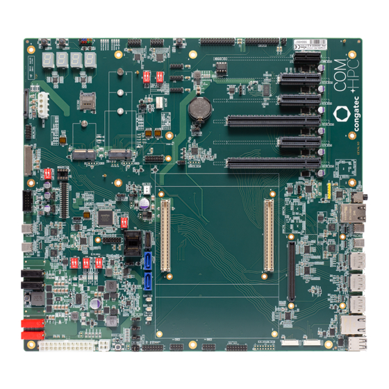
Congatec conga-HPC/EVAL-Client User Manual (65 pages)
COM-HPC Client Module Size A, B, C evaluation carrier board
Brand:
Congatec
| Category:
Motherboard
| Size: 5 MB
Table of Contents
Table of Contents
8
Introduction
11
COM-HPC Client Concept
11
Table 1 COM-HPC ® Interface Summary
11
Conga-HPC/EVAL-Client
12
Order Number
12
Table 2 Order Description
12
Connector Layout
13
Specifications
14
Feature List
14
Table 3 Feature Summary
14
Mechanical Dimensions
15
Environmental Specifications
15
Connectors and Features
16
Table 4 Connector P1 (X1) Pinout
16
Table 5 Connector P2 (X4) Pinout
19
Power Supply Connectors
22
ATX Power Connectors
22
Table 6 SW15.1 - ATX/AT PSU Settings
22
Table 7 JP13 - ATX 5V Standby Settings
23
Table 8 X63 - 24-Pin ATX Power Pinout
23
DC Banana Jacks
24
Table 9 X64 - 4-Pin ATX12V Power Pinout
24
Table 10 X67, X68, X69, X70 - DC Banana Jacks Pinout
24
Table 11 SW15.2 - Buck-Boost Converter Settings
24
Power States Leds
25
VIN_PWR_OK Signal
25
Table 12 Power Leds Status
25
Table 13 JP11 - VIN_PWR_OK Signal Settings
25
Power-Up Control
26
Module Type Detection
26
Table 14 Module Type Detection Pinout Description
26
CMOS Battery Holder
27
Table 15 JP12 - TYPE0 Signal Settings
27
Table 16 JP9 - Battery Settings
27
Pcie Connectors
28
Pcie X16 Slots
28
Pcie X4 Slots
28
Pcie BMC Slot
29
Table 17 JP1 - Pcie Clock Request Signal Settings
29
M.2 Key B + Micro-SIM Card Slot
30
Table 18 JP1 - Pcie Clock Request Signal Settings
30
M.2 Key E
31
Table 19 SW1 - M.2 Key B Settings
31
Table 20 SW2 - M.2 Key B Settings
31
Table 21 JP1 - Pcie Clock Request Signal Settings
32
Table 22 SW3 - M.2 Key E Control
32
Display Interfaces
33
Edp/Lvds
33
Table 23 SW4.1 - Edp/Lvds Settings
33
Lvds
34
Table 24 X29 - LVDS Pinout
34
Edp
35
Table 25 X30 - Edp Pinout
35
Edp Panel and Backlight Power Supply
36
Flat Panel and Backlight Voltage Selection
36
Table 26 X31 - Edp Power Pinout
36
Table 27 JP3 - Flat Panel Voltage Settings
36
Table 28 JP4 - Backlight Voltage Settings
36
Flat Panel Configuration Data
37
Universal Serial Bus (USB)
37
USB4 Type-C Ports
37
Dual Stacked USB 2.0 Type-A Ports
38
Sata
38
Disk Drive Power Connector
38
Table 29 X35 - Disk Drive Power Pinout
38
SATA Power
39
Ethernet Ports
39
Table 30 X34 - SATA Power Pinout
39
Table 31 X37, X39 - Ethernet Status Leds Description
39
Ethernet Mezzanine Card Connector
40
Table 32 X36 - NBASET0_SDP Header Pinout
40
Table 33 X38 - NBASET1_SDP Header Pinout
40
Table 34 X54 - Ethernet Mezzanine Card Connector Pinout
40
Audio Interfaces
42
Audio Jack (4-Pole)
42
I²S/Soundwire
42
Table 35 X49 - Audio Jack Pinout
42
Table 36 X50 - I²S/Soundwire Header Pinout
42
DMIC
43
I 2 C Buses
43
Table 37 X48 - DMIC Header Pinout
43
SPI Flash Socket
44
Table 38 BIOS Select Options
45
Intel ISP Adaptor-C2 Connector
46
Table 39 X53 - Intel ISP Adaptor-C2 Connector Pinout
46
Table 40 JP8 - Debug Reset Trigger Signal Settings
46
General Purpose SPI Port
47
Espi
47
Table 41 CN2 - General Purpose SPI Port Pinout
47
Table 42 SW6.1 - Super I/O Settings
48
Table 43 SW6.2 - ESPI_CSI[0:1]# Settings
48
Table 44 SW5 - Super I/O Settings
48
Espi Header
49
Serial Ports
49
COM Port 0 Header
49
Table 45 X44 - Espi Header Pinout
49
Table 46 SW7 - COM Port 0 Transceiver Settings
50
Table 47 SW8 - COM Port 0 Transceiver Settings
50
Table 48 X46 - COM 0 Pinout
50
COM Port 1 Header
51
Module Serial Port 0
51
Table 49 X45 - COM 1 Header Pinout
51
Table 50 X42 - UART0 Pinout
51
Module Serial Port 1
52
Table 51 JP5 - UART0 and UART1 Power Settings
52
Table 52 X43 - UART1 Pinout
52
Table 53 JP5 - UART0 and UART1 Power Settings
52
System Fan Header
53
Table 54 X47 - SYS Fan Pinout
53
Table 55 JP6 - Fan Voltage Settings
53
Table 56 JP7 - Fan Speed Settings
53
CPU Fan Header
54
Debug Header
54
Table 57 X62 - CPU Fan Header Pinout
54
Table 58 JP10 - CPU Fan Voltage Control
54
Table 59 X57 - Debug Header Pinout
54
Feature Connector
55
Table 60 X55 - Feature Connector Pinout
55
GPIO Pin Header
56
Table 61 X58 - GPIO Header Pinout
56
I2C0 Pin Header
57
I2C1 Pin Header
57
Table 62 X59 - I2C0 Pin Header Pinout
57
Table 63 X60 - I2C1 Pin Header Pinout
57
Smbus Pin Header
58
Front Panel Pin Header
58
Table 64 X61 - Smbus Header Pinout
58
Table 65 X56 - Front Panel Pin Header Pinout
58
I2C I/O Expander Pin Header
59
Table 66 X52 - I2C Header Pinout
59
CSI Port 0
60
Table 67 X40 - CSI Port 0 Pinout
60
CSI Port 1
61
Table 68 X41 - CSI Port 1 Pinout
61
Additional Features
62
Buttons
62
Power
62
Reset
62
Lid
62
Sleep
63
Ground Test Points
63
Debug Display
63
Debug Leds
64
Mechanical Dimensions
65
Advertisement
Advertisement
Related Products
Congatec conga-HPC/EVAL-Server
Congatec conga-IGX
Congatec COM Express conga-BM67
Congatec COM Express conga-BS67
Congatec COM Express conga-TR3
Congatec conga-IC175
Congatec Qseven conga-QA5
Congatec conga-PA5 Series
Congatec conga-IA4
Congatec SMARC conga-SMC1
Congatec Categories
Motherboard
Computer Hardware
Control Unit
Microcontrollers
Single board computers
More Congatec Manuals
Login
Sign In
OR
Sign in with Facebook
Sign in with Google
Upload manual
Upload from disk
Upload from URL