
Related Manuals for Panametrics C-RL


Summary of Contents for Panametrics C-RL
- Page 1 Flow Model C-RL Ultrasonic Flow Transducer Instruction Manual 916-062 B panametrics.com July 2021...
- Page 3 Flow Model C-RL Ultrasonic Flow Transducer Installation Guide 916-062 B July 2021 panametrics.com Copyright 2021 Baker Hughes company. This material contains one or more registered trademarks of Baker Hughes Company and its subsidiaries in one or more countries. All third-party product and company names are trademarks of their respective...
- Page 4 [no content intended for this page]...
- Page 5 If you do, serious injury can result. WARNING! Make sure that power to the auxiliary equipment is turned OFF and locked out before you perform maintenance procedures on the equipment. Model C-RL User’s Manual...
- Page 6 The crossed-out wheeled bin symbol invites you to use those systems. If you need more information on the collection, reuse and recycling systems, please contact your local or regional waste administration. Visit www.bakerhughesds.com/health-safetyand-environment-hse for take-back instructions and more information about this initiative. Model C-RL User’s Manual...
-
Page 7: Table Of Contents
4.8 Transducer Specifications ................. . 41 Model C-RL Installation Guide... - Page 8 Contents Model C-RL Installation Guide...
-
Page 9: Introduction
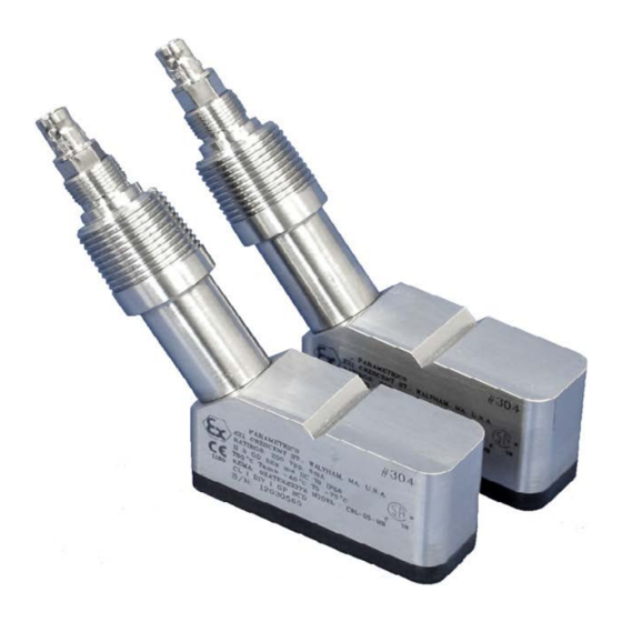
Introduction The C-RL clamp-on ultrasonic flow transducers are used exclusively with the Panametrics Measurement & Control line of ultrasonic flowmeters. These transducers are used to measure the flow of various gases through pipes having diameters from 3/4 in. (20 mm) to 30 in. (750 mm). Such measurements are independent of the pipe material. This manual provides details on the following topics: •... -
Page 10: Dampening Material
• The pipe experiences constant condensation on the outside. Note: Consult a Panametrics flowmeter applications engineer or sales engineer if you have any questions regarding dampening material. Details for properly installing the dampening material are discussed later in this manual. -
Page 11: Installing The C-Rl Transducers
Installing the C-RL Transducers Panametrics Measurement & Control offers the following transducer mounting fixtures to suit your applications needs: • V1 clamping fixture • V4 clamping fixture • V8 clamping fixture • V12 clamping fixture • PI clamping fixture Figure 2 below and Figure 3 on page 4 show the V1, V4, V8, V12 and PI fixture assemblies. Each type of transducer and fixture requires the installation of dampening material for acoustic isolation. - Page 12 V1 Fixture V4 Fixture V8 Fixture PI Fixture Figure 3: The V1, V4, V8 and PI Mounting Fixtures Model C-RL Installation Guide...
-
Page 13: Choosing An Installation Location
Place the transducers as close as possible to the horizontal plane. Locate the transducers on opposite sides of the pipe 180 apart, ideally at the 3 and 9 o’clock positions. IMPORTANT: Do not locate the transducers on the top or the bottom of the pipe. Pipe Transducer Signal Path End View Model C-RL Installation Guide... -
Page 14: Obtaining The Transducer Spacing
1” box wrench or 10” adjustable wrench • other safety equipment appropriate for your application DMP-1 DMP-3 • utility knife • gloves • 7/16” box wrench or a 4” adjustable wrench • spatula or putty knife (to remove access dampening compound) Model C-RL Installation Guide... - Page 15 Use the edge of the block shown below as the setting point. Zero Point on Measuring Scales Set Screw Mounting Block Set at 1 in. (2.5 cm) using Set at 1 in. (2.5 cm) this edge of block Top View Model C-RL Installation Guide...
- Page 16 The overall spacing between blocks should be either left edge to left edge or right edge to right edge. Note: If possible, the second block should also be set at least 1 in.(2.5 cm) from the edge of the fixture. Set second block Zero Point on using this edge Measuring Scales Top View Model C-RL Installation Guide...
- Page 17 Make sure you reassemble the fixture properly to ensure the correct transducer spacing. If the fixture has rulers on the rails, make sure the zero points on each ruler are at the same end of the fixture as shown below. Model C-RL Installation Guide...
- Page 18 Measuring Scales Top View Install the four nuts onto the threaded rods with the convex side of the nut facing the fixture. Hand tighten each nut evenly as shown below. Do not use a cross-tightening pattern. Model C-RL Installation Guide...
- Page 19 Nuts Nuts (2 places) (2 places) Top View Tightening Pattern of Bolts Tighten equally first Tighten equally second Side View Model C-RL Installation Guide...
- Page 20 TIP: If you are concerned about removing the reference lines during cleaning, use a tape measure and measure 2 ft (60 cm) from one of the reference lines and mark another line (temporary or permanent). This line can be used as a reference point later. Model C-RL Installation Guide...
- Page 21 • DMP-1, proceed to “Applying the DMP-1 Dampening Material” on page 14 • DMP-3, proceed to “Applying DMP-3 Compound” on page 16 • PDJ, proceed to “Installing the Pipe Dampening Jacket - PDJ” on page 18 Model C-RL Installation Guide...
- Page 22 With a marker, trace around the transducer footprint. Remove the fixture and the transducers. Use a utility knife to cut out the area under the transducer footprint. Peel the cut material off the pipe, as shown below. Model C-RL Installation Guide...
- Page 23 10. Wrap each of these strips around the pipe on the outside edge of the clamping fixture, one upstream and one downstream. The completed dampening material installation should appear similar to the figure below, which also shows the transducers. 11. To mount transducers, refer to “Mounting the Transducers” on page 20 . Model C-RL Installation Guide...
- Page 24 (see Step 3 in “Installing the Fixture” on page 9 ). After the fixture is on the pipe, tighten the four nuts with a 1-in. box wrench. DO NOT use a cross-tightening pattern. Model C-RL Installation Guide...
- Page 25 Using a putty knife or other suitable tool, remove the DMP-3 material from the transducer locations. To mount the transducers, refer to “Mounting the Transducers” on page 20 . Model C-RL Installation Guide...
- Page 26 3 o’clock and 9 o’clock positions. Note: Panametrics recommends placing the PDJ on the pipe so that the seam is as close to the top of the pipe as possible. Placing the seam at the top of the pipe reduces the amount of dripping.
- Page 27 After the fixture has been mounted on the pipe, tighten the four nuts with a 1-in. box wrench. DO NOT use a cross-tightening pattern. To mount the transducers, refer to “Mounting the Transducers” on page 20 . Model C-RL Installation Guide...
- Page 28 (see the figure below). Tighten the pressure bolts by hand just enough to bring the transducers into contact with the pipe surface and to hold the transducers in place. IMPORTANT: Do not use a wrench or pliers on the pressure bolts. Model C-RL Installation Guide...
-
Page 29: What's Next
• Make a note of the installation date and set a schedule for periodic inspection and tightening of the clamping fixture nuts to ensure that the clamping fixture does not become loose and fall, possibly causing injury. Model C-RL Installation Guide... -
Page 30: Installing The Pi Fixture And Transducers
1” box wrench or 10” adjustable wrench • other safety equipment appropriate for your application DMP-1 DMP-3 • utility knife • gloves • 7/16” box wrench or a 4” adjustable wrench • spatula or putty knife (to remove access dampening compound) Model C-RL Installation Guide... - Page 31 5% among the six spots. If you encounter more than a 5% variation among the six spots, move to another section of the pipe. Verify that the wall thickness at both transducer locations has less than the 5% variation. Model C-RL Installation Guide...
- Page 32 Line up the zero scale mark of the layout tape at the desired transducer location (e.g., 3 or 9 o’clock) for the first transducer. Mark a line ( origin line ) at least 12 in. (30 cm) long. Model C-RL Installation Guide...
- Page 33 Mark a small scribe line at the 180 point. 180 deg and C/2 180 deg and C/2 Mark another origin line at the 180 point at least 12 in. (30 cm) long. Model C-RL Installation Guide...
- Page 34 The next series of steps depends on what type of dampening material you are using: • For PDJ, proceed to “Applying the Pipe Dampening Jacket - PDJ” on page 27 . • For DMP-1 and DMP-3, proceed to “Installing the First Transducer Mounting Block” on page 28 . Model C-RL Installation Guide...
- Page 35 3 o’clock and 9 o’clock positions. Note: Panametrics recommends placing the PDJ on the pipe so that the seam is as close to the top of the pipe as possible. Placing the seam at the top of the pipe reduces the amount of dripping.
- Page 36 Front Edge of Mounting Block Tighten the chain or strap around the pipe loosely enough so that the mounting block can be moved for minor adjustments, but not so loose that it will move without being touched. Model C-RL Installation Guide...
- Page 37 Also, make sure the front edge of the mounting block is still lined up with the circumferential line on the pipe. After the mounting block is properly aligned, tighten the chain or strap to secure the block in place. Model C-RL Installation Guide...
- Page 38 Chain from First Mounting Block Origin Line Side View S = Transducer Spacing Point (on opposite side of pipe) Using the layout tape, make a second circumferential line around the entire pipe at the second transducer spacing mark. Model C-RL Installation Guide...
- Page 39 J-hook. If you are using a strap, insert the J-hook into the smaller round holes on the strap. Tighten the chain or strap around the pipe loosely enough so that the mounting block can be moved for minor adjustments, but not so loose that it will move without being touched. Model C-RL Installation Guide...
- Page 40 Remove the dummy transducer block from the first mounting block and install it into the second mounting block. Insert the dummy block into the mounting block so the front edge of the dummy block lines up with the circumferential line as shown below. Model C-RL Installation Guide...
- Page 41 Also, make sure the front edge of the mounting block is still lined up with the circumferential line on the pipe. After the mounting block is properly aligned, tighten the chain or strap to secure the block in place. Model C-RL Installation Guide...
- Page 42 Origin Line Indicator Line Remove the dummy transducer block from the mounting block. Model C-RL Installation Guide...
- Page 43 (see the figure below). Tighten the pressure bolts by hand just enough to bring the transducers into contact with the pipe surface and to hold the transducers in place. IMPORTANT: Do not use a wrench or pliers on the pressure bolts. Model C-RL Installation Guide...
- Page 44 Locking Nut Side View The next series of steps depends on what type of dampening material you are using. If you are using: • DMP-1, proceed to “Installing DMP-1 Dampening Material” on page 37 Model C-RL Installation Guide...
- Page 45 One strip will be upstream from the flow measurement point, while the other strip will be downstream form the flow measurement point. The completed installation should appear similar to the figure below (for clarity, the junction boxes are not shown). Model C-RL Installation Guide...
- Page 46 Origin Line Circumferential Line Pressure Bolt Dummy Block Proceed to “What’s Next?” on page 39 . Model C-RL Installation Guide...
-
Page 47: What's Next
• After the flowmeter is placed into operation, measure and record the signal strength of each transducer using the flowmeter’s diagnostics menu. This value will be helpful when making periodic checks or for Model C-RL Installation Guide... -
Page 48: Maintenance
The transducers, couplant, clamping fixture and dampening material required for your installation are all provided by Panametrics. After you have completed your installation, little maintenance is required. However, see Table 1 below for those routine maintenance procedures which are recommended to ensure accurate operation. -
Page 49: Transducer Specifications
Transducer Specifications 4.8.1 C-RL Transducer Numbers 301, 302, 307 and 308 Table 2: Transducer Number Specification Primary Use Mid-sized pipes, Small pipes, Mid-size pipes, Small pipes, high temperature high temperature very high very high temperature temperature Installation Type Clamp-on Material of Construction... - Page 50 4.8.2 C-RL Transducer Numbers 304, 305 and 308 Table 3: Transducer Number Specification Primary Use Small pipes Low pressure, high Low pressure, high velocity; primarily velocity; primarily used with TAG used with TAG technology technology Installation Type Clamp on Material of Construction...
- Page 51 • If Panametrics determines that the damage is not covered under the terms of the warranty, or if the warranty has expired, an estimate for the cost of the repairs at standard rates will be provided. Upon receipt of the owner’s approval to proceed, the instrument will be repaired and returned.
- Page 52 Chapter Model C-RL Installation Guide...
- Page 53 When installing this apparatus, the following requirements must be met: • The certification covers the Panametrics clamp-on transducers fitted with an IME 7080 series enclosure (an Ex d & tb approved metal enclosure) and a clamping fixture, the assembly complying with the requirements of EN 60079-1 and EN 60079-31, and providing a degree of protection of IP6X.
- Page 54 National transposing legislation. C-Rx Transducer Assembly Details Manufacturer and certificate owner: Panametrics Infrastructure Sensing Inc., Billerica, MA 01821, USA. Alternative manufacturing site: Panametrics EMEA, Shannon, Co. Clare, Ireland QAN License Number:...
- Page 56 Customer Support Centers U.S.A. The Boston Center 1100 Technology Park Drive Billerica, MA 01821 U.S.A. Tel: 800 833 9438 (toll-free) 978 437 1000 E-mail: mstechsupport@bakerhughes.com Ireland Sensing House Shannon Free Zone East Shannon, County Clare Ireland Tel: +353 61 61470200 E-mail: mstechsupport@bakerhughes.com Copyright 2021 Baker Hughes company.
Need help?
Do you have a question about the C-RL and is the answer not in the manual?
Questions and answers