
Related Manuals for Panametrics T5


Summary of Contents for Panametrics T5
- Page 1 Flow T5 Flare Gas Transducer (Standard and Extended Velocity Range) Installation Guide 916-117 D panametrics.com AUG 2021...
- Page 3 Flow T5 Flare Gas Transducer (Standard and Extended Velocity Range) Installation Guide 916-117 D AUG 2021 panametrics.com Copyright 2021 Baker Hughes company. This material contains one or more registered trademarks of Baker Hughes Company and its subsidiaries in one or more countries. All third-party product and company names are trademarks of their respective...
- Page 4 [no content intended for this page]...
- Page 5 If you do, serious injury can result. WARNING! Make sure that power to the auxiliary equipment is turned OFF and locked out before you perform maintenance procedures on the equipment. T5 Flare Gas Transducer Installation Guide...
- Page 6 Environmental Compliance Waste Electrical and Electronic Equipment (WEEE) Directive Panametrics is an active participant in Europe’s Waste Electrical and Electronic Equipment (WEEE) take-back initiative, directive 2012/19/EU. The equipment that you bought has required the extraction and use of natural resources for its production. It may contain hazardous substances that could impact health and the environment.
- Page 7 Preface T5 Flare Gas Transducer Installation Guide...
- Page 8 Preface [no content intended for this page] T5 Flare Gas Transducer Installation Guide...
-
Page 9: Table Of Contents
T5 Transducer Certifications..................61 T5 Flare Gas Transducer Installation Guide... - Page 10 Contents viii T5 Flare Gas Transducer Installation Guide...
- Page 11 Contents T5 Flare Gas Transducer Installation Guide...
- Page 12 Contents T5 Flare Gas Transducer Installation Guide...
-
Page 13: Chapter 1. Installing Pipe Nozzles
Introduction Before the T5 transducers can be installed into the pipe, you will need to install pipe nozzles. Nozzles may be installed as part of a fabricated spoolpiece or by using the hot or cold tap process with a Panametrics Sensing Nozzle Installation Kit . -
Page 14: Identifying And Checking The Nozzle Installation Kit Components
After you are familiar with each component, verify that the welding bosses and alignment plate shipped are for the required transducer spacing and the pipe size described in the following steps. Welding Boss Nozzle Spacer Flange Threaded Rod with Washer and Nut Alignment Plate Figure 1: Components for Nozzle Installation Kit T5 Flare Gas Transducer Installation Guide... - Page 15 12.73 in. 4.5 in. Bias (9 in. Spacing) 14.14 in. Bolt location shown for 150# rating. 5 in. Bias (10 in. Spacing) 9.05 in. 3.2 in. Bias (6.4 in. Spacing) T5 Flare Gas Transducer Installation Guide...
-
Page 16: Selecting And Marking The Pipe For Nozzle Locations
Undisturbed flow means avoiding sources of turbulence such as flanges, elbows and tees; avoiding swirl; and avoiding disturbed flow profiles. Never install the flowmeter downstream of control valves, especially butterfly valves. If you cannot find a proper location, please consult with Panametrics Flow Application engineering. - Page 17 7 for arc distances for the most commonly used pipe sizes. If your pipe size is not shown in Table 1 , use the equation in the figure on page 6 to calculate the arc distance. T5 Flare Gas Transducer Installation Guide...
- Page 18 L = Arc Length along pipe surface Spacing Calculate L as follows: L = 3.142 x R x A Where A = Sin R = Radius in inches S = Bias in inches End View T5 Flare Gas Transducer Installation Guide...
-
Page 19: Installing The First Welding Boss
That is, the shorter side of the boss should be closer to the original scribed pipe centerline. T5 Flare Gas Transducer Installation Guide... - Page 20 The boss is constructed of carbon steel. Check the alignment again. If the boss is misaligned by 0.02 in. (0.5 mm) or more, remove the boss, grind off the welds and reinstall the boss. T5 Flare Gas Transducer Installation Guide...
-
Page 21: Installing The First Nozzle
End View Insert the pipe section of the jig (the key cut section) into the pipe section of the nozzle, and fasten the assembly together using four nuts and bolts. Bolts Nozzle Side View T5 Flare Gas Transducer Installation Guide... - Page 22 If the root gap is larger than the 0.094 in. (2.4 mm) dimension evenly all the way around the nozzle, then suitably sized washers may be inserted between the jig and the nozzle to reduce the root gap dimension. T5 Flare Gas Transducer Installation Guide...
-
Page 23: Installing The Second Welding Boss
Screw the threaded rod into the second boss. Then, insert the bolt/boss assembly into the jig key cut grooves and secure it with a washer and nut on top. Threaded Rod Welding Boss Side View Washer and Nut to Secure Threaded Rod Welding Boss Side View T5 Flare Gas Transducer Installation Guide... - Page 24 Remove the threaded rod and the jig. Leave the alignment plate bolted to the first nozzle, with the spacer flange sandwiched between them. T5 Flare Gas Transducer Installation Guide...
-
Page 25: Installing The Second Nozzle
Complete the root pass and subsequent filler passes as required. Allow the weld to cool, and then remove all nuts and bolts, the alignment plate, the jig, the spacer flange and the threaded rod. The completed installation should appear as shown below. T5 Flare Gas Transducer Installation Guide... -
Page 26: Hot Tapping The Pipe
The procedure for cold tapping a pipe is the same as the hot tapping procedure described above. However, isolation valves are not necessary during the tapping process. The hot tap machine is used directly on the nozzles. The isolation valves are added after the tapping process has been completed. T5 Flare Gas Transducer Installation Guide... -
Page 27: Tilted 45° Installation
IMPORTANT: You will need eight 5/8” studs with two nuts each, or 3/4” studs with two nuts each. The 5/8” studs are needed for 2”-150#, 2”-300# and 3”-150# flanges. The 3/4” studs are needed for 3”-300# flanges. Welding Boss Nozzle Threaded Rod with Washer and Nut Figure 2: Components for Nozzle Installation Kit T5 Flare Gas Transducer Installation Guide... -
Page 28: Selecting And Marking The First Nozzle Location
Undisturbed flow means avoiding sources of turbulence such as flanges, elbows and tees; avoiding swirl; and avoiding disturbed flow profiles. Never install the flowmeter downstream of control valves, especially butterfly valves. If you cannot find a proper location, please consult with Panametrics Flow Application engineering. - Page 29 3 o’clock and 9 o’clock positions for a horizontal pipe. Note: If you cannot find a proper location, please consult with Panametrics Flow Application engineering. At the 3 o’clock position, center punch the pipe to mark the position for the center of the first nozzle.
-
Page 30: Determining And Marking The Second Nozzle Location
Width - equal to the average pipe O.D., as calculated in Step 1 above. • Length - equal to 4 times the average pipe O.D., as calculated in Step 1 above. • Average O.D. 4 X O.D. T5 Flare Gas Transducer Installation Guide... - Page 31 Remove the strip of film and fold it as shown below to determine the position which is diametrically opposite the overlap position when the film is reapplied to the pipe. Overlap Mark Fold to Here Mark the outside of the fold for reference. Mark the Edge T5 Flare Gas Transducer Installation Guide...
- Page 32 Fold Mark Second Edge Side View Remove the strip of film from the pipe. 10. Scribe 6 in. long vertical and horizontal lines which intersect at the new center-punch mark. Scribe Lines Side View T5 Flare Gas Transducer Installation Guide...
-
Page 33: Installing The First Welding Boss
Scribe the oblique center line on the pipe at the calculated distance from the true center line. The oblique center line should be marked on the side of the true center line that is closer to the second nozzle location. Oblique Center Line True Center Line Side View T5 Flare Gas Transducer Installation Guide... - Page 34 Remove the clamp and check the alignment again. If the boss is misaligned by 0.02 in. (0.5 mm) or more, remove the boss, grind off the welds and reinstall the boss. T5 Flare Gas Transducer Installation Guide...
-
Page 35: Installing The First Nozzle
Slide the nozzle over the threaded rod, and align the contoured end of the nozzle so that it matches the pipe arc. Then slide the jig over the threaded rod and fit the jig into the welding boss. Threaded Rod Nozzle T5 Flare Gas Transducer Installation Guide... - Page 36 0.6 in. (15 mm) in length. Allow the weld to cool for 30 seconds between tacks. Complete the root pass and subsequent filler passes as required. Allow the weld to cool, and then remove the nut, washer, jig and threaded rod. T5 Flare Gas Transducer Installation Guide...
-
Page 37: Installing The Second Welding Boss And Nozzle
Using the same procedures used for installing the first welding boss and nozzle, install the second welding boss and nozzle at the marked position on the pipe . The completed installation should appear as shown below. NOZZLE 2 PLACES WELDING BOSS 2 PLACES FLOW 45° T5 Flare Gas Transducer Installation Guide... -
Page 38: Hot Tapping The Pipe
(100 m/s, 328 ft/s) installation. Except for the 4 in. pipe size, cold tapping can be performed only before the isolation valve is installed. The hot tap machine is used directly on the nozzles, and the isolation valves are added after the tapping process has been completed. T5 Flare Gas Transducer Installation Guide... -
Page 39: Chapter 2. Installing The Isolation Valves
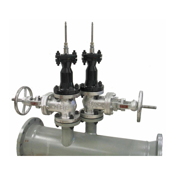
Install one of the isolation valves, including a suitable gasket, on each of the nozzles. Secure the valves with 5/8 in. studs and nuts. Orient the isolation valve handles to minimize interference during operation of the valves. T5 Flare Gas Transducer Installation Guide... -
Page 40: Tilted 45° Installation (Extended Velocity Range)
The wedge positions are based on the need to tilt the transducer 6° against the flow. Flow Direction Nut Side Marking on Bolt Spacer Nozzle Face Marking on 6° Wedge Valve Face Marking on 6° Wedge Figure 4: Mounting Bolts, Bolt Spacers, Wedge and Gaskets Positions T5 Flare Gas Transducer Installation Guide... - Page 41 (see Figure 5 below). Nut Side Marking on Bolt Spacer Figure 5: Mounting the Isolation Valve T5 Flare Gas Transducer Installation Guide...
- Page 42 After the wedge is positioned correctly, use two wrenches to tighten the hardware and secure the isolation valve to the nozzle. Then remove the adjustment screws from the wedge. Figure 7: Completed Isolation Valve Installation Note: The upstream valve and transducer are installed without wedges, as described in the previous section. T5 Flare Gas Transducer Installation Guide...
-
Page 43: Chapter 3. Installing The Transducer Assemblies
Before mounting the insertion mechanism on the isolation valve you should familiarize yourself with its components (see the figure below): • Junction box • Barrel • Packing gland • Transducer Note: Explosion-proof junction boxes are not pre-mounted on the end of the transducer when shipped. T5 Flare Gas Transducer Installation Guide... - Page 44 Chapter 3. Installing the Transducer Assemblies Junction Box Packing Gland Barrel Transducer Transducer (180° head shown) (90° head shown) T5 Flare Gas Transducer Installation Guide...
- Page 45 IMPORTANT: The stop ring at the end of the barrel should be loose. DO NOT tighten the compression fitting or you could change the transducer alignment. Remove the four bolts that fasten the barrel to the packing gland. Top Compression Fitting Four Bolts Stop Ring T5 Flare Gas Transducer Installation Guide...
- Page 46 Retract the barrel from the packing gland so that the transducer head is recessed in the packing gland. You will hear the stop ring click into place when the transducer is fully recessed. Compression Fitting (hand tight) T5 Flare Gas Transducer Installation Guide...
- Page 47 Visually inspect the mechanism. Make sure the transducer is recessed in the packing gland. Again, make sure the top compression fitting is secure and hand tight. Bias 90 Assembly with 90° Head Transducer Recessed in Packing Gland Tilted Diameter Assembly with 180° Head Transducer Recessed in Packing Gland T5 Flare Gas Transducer Installation Guide...
-
Page 48: Mounting The Bias 90 Insertion Mechanism/Transducer Assembly
Verify that the isolation valves are securely installed with gaskets and hardware. Then, place a gasket on the face of each isolation valve. Gasket Gasket Isolation Valve Isolation Valve Upstream Transducer Location Downstream Transducer Location T5 Flare Gas Transducer Installation Guide... - Page 49 Downstream at the end of the assembly near the junction box (see the figure below). Proceed with either the upstream or downstream assembly. Lift the insertion mechanism by the barrel and place the insertion mechanism on the isolation valve. Downstream Transducer Assy. Identification Ring (on Extended Range Version) T5 Flare Gas Transducer Installation Guide...
- Page 50 Line up the flange holes and bolt the packing gland to the isolation valve. Packing Tool Bolts Using the packing tool, tighten the packing nut again so the nut is recessed. WARNING! The packing material must be securely packed before the isolation valve is opened. T5 Flare Gas Transducer Installation Guide...
-
Page 51: Inserting The Bias 90 Transducer Into The Pipe
All bolts are secure • The transducer head is recessed in the packing gland Barrel Bolts Packing Gland WARNING! Follow all applicable safety codes and practices before opening the isolation valve. Open the isolation valve. T5 Flare Gas Transducer Installation Guide... - Page 52 For this Bias 90 configuration, orient the alignment marks on each barrel flange so that they are facing each other. The alignment mark, which is marked with yellow paint, is scribed on the top and outside of the flange. Alignment Marks T5 Flare Gas Transducer Installation Guide...
- Page 53 Install the second insertion mechanism by repeating the steps in the two previous sections. After the second insertion mechanism is installed, proceed to one of the following sections: • “Aligning the Transducers (Standard Velocity Range)” on page 42 • “Aligning the Transducers (Extended Velocity Range)” on page 42 T5 Flare Gas Transducer Installation Guide...
-
Page 54: Aligning The Transducers (Standard Velocity Range)
6° away from the upstream transducer signal. Verify that the downstream transducer is located on the right to a person looking from the downstream end of the pipe (see Figure 8 below). Contact Panametrics if the port locations do not follow this convention. Upstream... - Page 55 Place the cover plate on top of the guide plate and slide it as far as possible until it is positioned around the upstream transducer, as shown in Figure 10 below. Then, tighten the screws to secure it. Upstream Cover Plate Transducer Figure 10: Installing the Cover Plate T5 Flare Gas Transducer Installation Guide...
- Page 56 (see Figure 12 below). Then, re-tighten the nuts. Downstream Transducer Collar 0° Mark Nuts on Flange Guide Plate Line Figure 12: Locking Collar 0° Mark Aligned with Guide Plate Line T5 Flare Gas Transducer Installation Guide...
- Page 57 Place the remaining bolts into the flanges and tighten them securely. Place a tag on each isolation valve stating the following: DO NOT OPERATE (CLOSE) WHEN TRANSDUCER IS INSERTED INTO PIPE. 10. Refer to your flowmeter Startup Guide to make the transducer electrical connections. T5 Flare Gas Transducer Installation Guide...
-
Page 58: Mounting The Tilted 45 Insertion Mechanism/Transducer Assembly
Lift the gasket and insert the packing tool into the packing nut. Turning the packing tool clockwise, tighten the packing material so that the barrel will stay up without support. Gasket Barrel Packing Tool T5 Flare Gas Transducer Installation Guide... - Page 59 GASKET 3 INCH 150 LB, RF WELDING NECK FLANGE 2 PLACES; REF ONLY 3 INCH SCH 80 PIPE NOZZLE 2 PLACES; REF ONLY FLOW GASKET DOWNSTREAM TRANSDUCER PORT Figure 14: Standard Velocity Range Assembly T5 Flare Gas Transducer Installation Guide...
- Page 60 2 PLACES; REF ONLY FLOW RECOVERY ANGLE BOLT/NUT SPACER GASKET(S) RECOVERY ANGLE WEDGE GASKET 3 INCH 150 LB RF, FULL OPENING DOWNSTREAM ISOLATION BALL VALVE TRANSDUCER PORT 2 PLACES; REF ONLY Figure 15: Extended Velocity Range Assembly T5 Flare Gas Transducer Installation Guide...
- Page 61 Downstream at the end of the assembly near the junction box (see the figure below). Proceed with either the upstream or downstream assembly. Lift the insertion mechanism by the barrel and place the insertion mechanism on the isolation valve. Downstream Transducer Assy. Identification Ring (on Extended Range Version) T5 Flare Gas Transducer Installation Guide...
- Page 62 Chapter 3. Installing the Transducer Assemblies Mounting the Tilted 45 Insertion Mechanism/Transducer Assembly (cont.) Line up the flange holes and bolt the packing gland to the isolation valve. Bolts T5 Flare Gas Transducer Installation Guide...
- Page 63 Mounting the Tilted 45 Insertion Mechanism/Transducer Assembly (cont.) Using the packing tool, tighten the packing nut again until the nut is recessed. WARNING! The packing material must be securely packed before the isolation valve is opened. Packing Tool T5 Flare Gas Transducer Installation Guide...
-
Page 64: Inserting The Tilted 45 Transducer Into The Pipe
All bolts are secure • The transducer head is recessed in the packing gland Barrel Bolts Packing Gland WARNING! Follow all applicable safety codes and practices before opening the isolation valve. Open the isolation valve. T5 Flare Gas Transducer Installation Guide... - Page 65 You may have to twist the barrel to get it moving. Place Hands Here Transducer Place the bolts into the flange joining the barrel flange to the packing gland flange. Tighten the bolts securely. Bolts T5 Flare Gas Transducer Installation Guide...
-
Page 66: Connecting An Xamp
If the BNC head is not positioned approximately where it is pictured in Figure 16 above, loosen the compression fitting and adjust the transducer. Then, re-tighten the compression fitting. T5 Flare Gas Transducer Installation Guide... - Page 67 5 threads of engagement (see Figure 17 below). Figure 17: Torquing the Cable Gland Verify that, with the transducer and the cable gland assembled, the junction box looks like Figure 18 below: Figure 18: Assembled Transducer and Cable Gland T5 Flare Gas Transducer Installation Guide...
- Page 68 Figure 19: Connecting BNC Plug to the Cable Connect the female BNC plug of the XAMP to the male BNC transducer head as shown in Figure 20 below: Figure 20: Female Plug to Male BNC Head T5 Flare Gas Transducer Installation Guide...
- Page 69 XAMP rest naturally according to the slant at which they exit the epoxy. The XAMP should remain still, and the cap of the junction box should rotate freely around the XAMP. Figure 22: Junction Box Cap T5 Flare Gas Transducer Installation Guide...
- Page 70 (see Figure 23 below) to secure the cap in place. Figure 23: Junction Box Set Screw To disconnect or uninstall the XAMP from the assembly, perform the above steps in reverse order. Note: T5 Flare Gas Transducer Installation Guide...
- Page 71 Chapter 3. Installing the Transducer Assemblies Connecting an XAMP (cont.) Figure 24: Transducer Arrangement (dwg. #752-063, rev. L) T5 Flare Gas Transducer Installation Guide...
- Page 72 Chapter 3. Installing the Transducer Assemblies [no content intended for this page] T5 Flare Gas Transducer Installation Guide...
-
Page 73: Chapter 4. Specifications
F (–40° to +60 KEMA 01ATEX2045X: IECEx KEM09.0009X European/International - Standards used: EN 60079-0:2012, EN 60079-1:2007, IEC 60079-0:2011, Flameproof: IEC 60079-1:2007, Ed. 6. IP66, TYPE 4X 200Vpp, 5mA North American - Weatherproof: European/International - IP 66 Weatherproof: T5 Flare Gas Transducer Installation Guide... - Page 74 Chapter 4. Specifications [no content intended for this page] T5 Flare Gas Transducer Installation Guide...
- Page 75 RETURN AUTHORIZATION NUMBER (RAN), and shipping instructions for the return of the instrument to a service center will be provided. If Panametrics Sensing instructs you to send your instrument to a service center, it must be shipped prepaid to the authorized repair station indicated in the shipping instructions.
- Page 76 Warranty [no content intended for this page] T5 Flare Gas Transducer Installation Guide...
- Page 78 Customer Support Centers U.S.A. The Boston Center 1100 Technology Park Drive Billerica, MA 01821 U.S.A. Tel: 800 833 9438 (toll-free) 978 437 1000 E-mail: mstechsupport@bakerhughes.com Ireland Sensing House Shannon Free Zone East Shannon, County Clare Ireland Tel: +353 (0)61 470200 E-mail: mstechsupport@bakerhughes.com Copyright 2021 Baker Hughes company.
Need help?
Do you have a question about the T5 and is the answer not in the manual?
Questions and answers