
Subscribe to Our Youtube Channel
Related Manuals for Henny Penny LOV LVG-102


Summary of Contents for Henny Penny LOV LVG-102
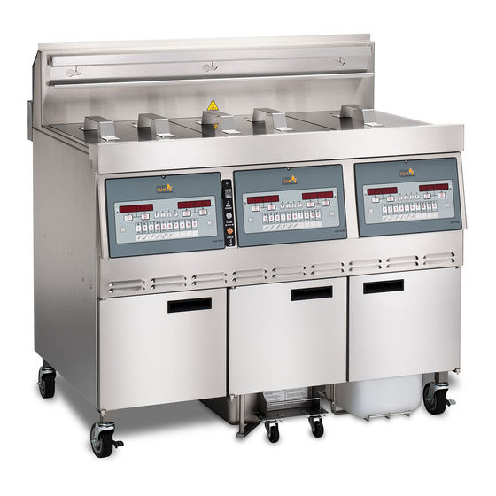
- Page 1 Model LVG-102, 103, 104 Henny Penny Split Vat & Full Vat Open Fryers – Model LVG-102 Model LVG-103 Model LVG-104 TECHNICAL MANUAL...
- Page 2 Model LVG-102, 103, 104...
-
Page 3: Table Of Contents
Model LVG-102, 103, 104 TABLE OF CONTENTS Section Page Section 1. TROUBLESHOOTING ....................1-1 Introduction ....................1-1 Safety ......................1-1 Troubleshooting ....................1-2 Error Code Table .................... 1-7 Section 2. INFO, FILTER & TEMP BUTTON STATS ............... 2-1 INFO Button Stats ..................2-1 FILTER Button Stats .................. - Page 4 Model LVG-102, 103, 104 TABLE OF CONTENTS Section Page Section 7. MAINTENANCE SECTION (Continued) Solenoid Valves ....................7-9 Drain Valve Actuators ..................7-11 Filter Pump & Motor ..................7-12 7-10 AIF Pump ....................... 7-14 7-11 AIF PC Board ....................7-14 7-12 Transformers ....................
-
Page 5: Troubleshooting
Model LVG-102, 103, 104 SECTION 1. TROUBLESHOOTING 1-1. INTRODUCTION This section provides troubleshooting information in the form of an easy to read table. If a problem occurs during the first operation of a new fryer, recheck the installation per the Installation Section of the operator’s manual. Before troubleshooting, always recheck the operation pro- cedures per Section 3 of the operator’s manual. -
Page 6: Troubleshooting
Model LVG-102, 103, 104 1-3. TROUBLESHOOTING To isolate a malfunction, proceed as follows: 1. Clearly define the problem (or symptom) and when it occurs. Locate the problem in the Troubleshooting table. Review all possible causes. Then, one-at-a-time work through the list of corrections until the problem is solved. Refer to the maintenance procedures in the Maintenance Section to safely and properly make the checkout and repair needed. - Page 7 Model LVG-102, 103, 104 Problem Cause Correction POWER SECTION • • With power switch in Open circuit Check to see that unit is plugged in ON position, the fryer • is completely inoperative Check the breaker or fuse (NO POWER) at supply box •...
- Page 8 Model LVG-102, 103, 104 Problem Cause Correction HEATING OF SHORTENING SECTION (Continued) Oil will not heat • • Drain valve open Close drain valve (Continued) • • Faulty temperature probe Replace temperature probe • • Faulty gas valve Check gas valve too slow •...
- Page 9 Model LVG-102, 103, 104 Problem Cause Correction OIL LEVEL SECTION Oil foaming or boiling over vat • Water in oil • At end of a Cook Cycle, drain and clean vat; add fresh oil • Improper or bad oil • Use recommended oil • Improper filtering • Refer to the procedure...
- Page 10 Model LVG-102, 103, 104 Problem Cause Correction FILTER MOTOR SECTION • Filter line connections • Tighten all filter line connections Filter motor runs but loose pumps oil slowly • Drain pan o-rings damaged or • Install new o-rings missing • Filter paper or pad clogged • Change filter paper or pad •...
- Page 11 Model LVG-102, 103, 104 1-4. ERROR CODES In the event of a control system failure, the digital display shows an error message. The message codes are shown in the DISPLAY column below. A constant tone is heard when an er- ror code is displayed, and to silence this tone, press any button.
- Page 12 Model LVG-102, 103, 104 1-4. ERROR CODES (Continued) DISPLAY CAUSE CORRECTION Pressure Switch failure/ hose loose Press power button to vat off and back on again, if E-20-B persists, have pressure switch checked; Draft Fan failure/ low voltage/ Flue should be open circuit if no air pressure; make sure “E-20-B”...
- Page 13 Model LVG-102, 103, 104 1-4. ERROR CODES (Continued) DISPLAY CAUSE CORRECTION AIF PC board not communicating Turn switch to OFF, then back to ON; if “E-60” with control PC board persists, check 1.5 amp fuse on AIF PC board on International units only;...
-
Page 14: Info, Filter & Temp Button Stats
Model LVG-102, 103, 104 SECTION 2. INFO, FILTER & TEMP BUTTON STATS 2-1. INFO BUTTON STATS Recovery Information for each Vat/OQM Information 1. Press and release and REC shows in left display and the recovery time that oil temperature went from 250°F (121°C) to 300°F (149°C) shows in the right display. -
Page 15: Hp Info Mode
Model LVG-102, 103, 104 2-4. HP INFO MODE Cook Cycles Remaining before Filtering Press and release both at the same time to enter HP Info Mode. You can view the following option in HP Info Mode: 1. E-Log 2. Last Load 3. -
Page 16: Level 1 Programming
Model LVG-102, 103, 104 SECTION 3. LEVEL 1 PROGRAMMING Level 1 contains the following: • Modify product settings • Set the AIF clock for products • Perform the Deep Clean procedure • Fryer Setup Mode 1. Press and hold buttons until LEVEL - 1 3-1. - Page 17 Model LVG-102, 103, 104 3-1. MODIFYING PRODUCT 8. Press and release button and “TEMP” shows in the SETTINGS (Continued) display, along with the preset temperature on the right side of the display. Press the product buttons to change the temperature. The temperature range is 190°F (88°C) to 380°F (193°C).
-
Page 18: Aif Clock
Model LVG-102, 103, 104 3-2. AIF CLOCK This feature allows controls to be set for periods of the day that block the automatic “Filter Now” prompts. For example, the controls could be set not interrupt with “Filter Now” prompts during the lunch rush, and during the supper rush. But, if filter- ing is desired during this time, press and hold a button to access the filter menu. -
Page 19: Deep Clean Mode
Model LVG-102, 103, 104 3-2. AIF CLOCK In 12-hour clock mode, there are three items on each line: the start (Continued) time “XX:XX”, the A or P (am/pm) setting, and the “XX” duration. Use the and buttons to set these items, which flashes when the item is selected. To set a new start time setting, use the product buttons, to enter the new value. Press the button to step over to the AM/PM setting. The A or P can be toggled by pressing the ‘0’... -
Page 20: Fryer Setup
Model LVG-102, 103, 104 3-4. FRYER SETUP This mode has the same settings as seen upon initial start-up of the fryer. 1. Press and hold buttons until LEVEL - 1 shows in the display, followed by ENTER CODE. 2. Enter code 1, 2, 3, 4 (first 4 product buttons). “PRODUCT” and “SELECTN”... - Page 21 Model LVG-102, 103, 104...
-
Page 22: Level 2 Programming
Model LVG-102, 103, 104 SECTION 4. LEVEL 2 PROGRAMMING Used to access the following: • Advanced changes to product settings • Error code log • Password programming • Alert Tone/Volume • No. of cook cycles before filter is suggested • Automatic filter time 4-1. ADVANCED PRODUCT 1. Press and hold buttons until LEVEL - 2 SETTINGS shows in the display, followed by ENTER CODE. -
Page 23: E-Log (Error Code Log)
Model LVG-102, 103, 104 4-1. ADVANCED PRODUCT 8. Press button until “FULL HT” shows in display along SETTINGS (Continued) with full heat value in seconds, which means heat is on as soon as a timer button is pressed, for a programmed length of time. -
Page 24: Passwords
Model LVG-102, 103, 104 4-3. PASSWORDS The 4-digit passwords can be changed for access to Set-Up, Usage, Level 1, Level 2, & Get Mgr.) 1. Press and hold buttons until LEVEL - 2 shows in the display, followed by ENTER CODE. 2. Enter code 1, 2, 3, 4 (first 4 product buttons). “PROD”... -
Page 25: Filter After
Model LVG-102, 103, 104 4-5. FILTER AFTER The number of cook cycles between filtering the oil can easily be programmed for all products. 1. Press and hold buttons until LEVEL - 2 shows in the display, followed by ENTER CODE. 2. Enter code 1, 2, 3, 4 (first 4 product buttons). “PROD” and “COMP” show in the displays. 3. Press button 4 times and “FILR AFTR”... -
Page 26: Level 3 Programming
Model LVG-102, 103, 104 SECTION 5. LEVEL 3 PROGRAMMING Used to access the following: • TECH RESETS-Reset Recovery Faults/Passwords to defaults • SPCL PROG-Program filter control parameters and other items • CLOCK SET-Set the time-of-day clock / calendar • DATA COMM-Data Communications, LonWorks, MMC, etc. • HEAT CTRL-Program heat algorithm control parameters • TECH MODE-Control of outputs, display & button tests, etc. •... -
Page 27: Special Programming
Model LVG-102, 103, 104 5-2. SPECIAL PROGRAMMING The Special Program Mode is used to set more detailed program- ming, such as: SP-1 • ZONE - USA or Non-USA (default setpoints) SP-2 • System Initialization SP-3 • 2nd Language: English, French, Candian- French, German, Spanish, Portuguese, Swedish, Russian, &... - Page 28 Not all Special Program Mode functions are discussed in this section. To ensure proper operation of fryer, please consult Henny Penny Corp. before changing any of these settings. For more information on these functions, contact the Service Department at 1-800-417- 8405, or 1-937-456-8405.
- Page 29 Model LVG-102, 103, 104 5-2. SPECIAL PROGRAMMING 2nd Language (SP-3) (Continued) 5. Press button and “SP-3 2ND LANGUAGE” scrolls in left display. Use buttons to set to: ENGLISH; FRANCAIS; CAN FREN; ESPANOL; PORTUG; DEUTSHE; SVENSKA; РУССКИИ or -NONE-. By setting a second language in the controls, 2 languages can now be easlily chosen by pressing button twice during normal operation.
- Page 30 Model LVG-102, 103, 104 5-2. SPECIAL PROGRAMMING Decal Layout (SP-8) (Continued) 9. Press button and “SP-8 DECAL LAYOUT?” scrolls in the left display. The words in the right displays should match the arrow type above the buttons. EX: If the control decal shows the right displays should show DOWN-UP If the displays show UP-DOWN, use the...
-
Page 31: Clock Set
Data communications and heat controls settings are shown in Level 3 Program Mode. But, to ensure proper operation of fryer, please consult Henny Penny Corp. before changing any of these settings. For more information on these functions, contact the Service Department at 1-800-417- 8405, or 1-937-456-8405. -
Page 32: Tech Mode
Model LVG-102, 103, 104 5-5. TECH MODE The TECH Mode has self-diagnostic information, which can be used by certified technicians for troubleshooting purposes, such • Software • Fryer Type (Gas or Elec.) • Push Button Test • All On Display Test • Display Segments Test • Display Digits Test •... - Page 33 Model LVG-102, 103, 104 5-5. TECH MODE (Continued) 1. To enter the TECH Mode, press and hold buttons for 5 seconds, until display shows ”LEVEL 3” followed by “ENTER CODE”. 2. Enter code 1, 1, 2, 2, 1, 1, 2, 2 (first 2 product buttons). “A. TECH” & “RESETS” show in the displays. 3.
- Page 34 Model LVG-102, 103, 104 5-5. TECH MODE (Continued) T-8 - DECIMAL PTS TEST Press any of the product buttons numerous times to view each LED across the control panel. T-17 - DIGITAL INPUTS - HDF H = HIGH LIMIT - If “H” is present, the high limit is good. If “-”...
- Page 35 Model LVG-102, 103, 104 5-5. TECH MODE (Continued) Press button and “INP E_P_” and “JL_R_DF_” shows in the displays. AIF Board Inputs: E = Stop button E* = E-Stop pressed. P = Drain Pan M* = drain pan is missing. JL = JIB J* = JIB oil level is low.
- Page 36 Model LVG-102, 103, 104 5-5. TECH MODE (Continued) T-20 - PUMPS & VALVES √ button and “VALVES” “DcRcAc” shows in displays. Press Press to open and close the drain valves. Press to open and close the return valves. Press to open and close the add valves. “DcRcAc”...
-
Page 37: Stats Mode
Model LVG-102, 103, 104 5-6. STATS MODE This mode allows a technician to view advanced information on the operation of the fryer and controls. 1. To enter the TECH Mode, press and hold buttons for 5 seconds, until display shows ”LEVEL 3”, followed by “ENTER CODE”. -
Page 38: Information Mode
Model LVG-102, 103, 104 SECTION 6. INFORMATION MODE 6-1. INFO MODE This mode gathers and stores historic information on the fryer and operator’s performance. Press and hold for 3 seconds, unitil *INFO* *MODE*” shows on the displays. Press buttons to access the steps and press √ button to view the statistics within each step. - Page 39 Model LVG-102, 103, 104 6-1. INFO MODE LAST LOAD (Continued) Press √ button to select Last Load (ex: -P1- = Product 1;”L1” = left, 1st product) and press buttons to view the following: FUNCTION DISPLAY EX: Product (Last product cooked) PRODUCT -P1- L1 Time of day last Cook Cycle was started STARTED 10.25A SEP-08...
-
Page 40: Preventive Maintenance
Model LVG-102, 103, 104 SECTION 7. MAINTENANCE 7-1. PREVENTIVE To ensure a long life of fryers and their components, regular MAINTENANCE maintenance should be performed. Refer to the chart below. Frequency Action Daily Mainteance Filter (See Maintenance Filtering Instructions Section in Operator’s Manual or PM Guide) Daily Change Filter Pad (See Changing... -
Page 41: Control Panel And Menu Card Replacement
Model LVG-102, 103, 104 7-3. CONTROL PANEL & Should the control panel become inoperative, or the menu card MENU CARD needs changed, follow these instructions: REPLACEMENT 1. Remove electrical power supplied to the vat. To avoid electrical shock or property damage, move the power switch to OFF and disconnect main circuit breaker, or unplug cord at wall receptacle. -
Page 42: High Temperature Limit Control
Model LVG-102, 103, 104 7-4. HIGH TEMPERATURE This is a safety, manual reset control, which senses the temper- LIMIT CONTROL ature of the oil. If the oil temperature exceeds 425°F (218°C), this switch opens and shuts off the heat to the vat and “E-10” shows in the display. - Page 43 Model LVG-102, 103, 104 7-4. HIGH TEMPERATURE Replacement: LIMIT CONTROL If the tube is broken or cracked, the control opens, shutting off (Continued) electrical power. The control cannot be reset. 1. Drain the oil from the vat, by pressing and holding a button until *FILTER* *MENU* shows in the display.
-
Page 44: Main Power Switch
Model LVG-102, 103, 104 7-4. HIGH TEMPERATURE 7. Using an 11/16” crows-foot, remove large high limit fitting LIMIT CONTROL in vat wall, and pull high limit from inside the control area. (Continued) 8. Install new high limit in reverse order and restore power to unit. 9. Fill vat by pressing and holding a button until *FILTER* *MENU* shows in the display. -
Page 45: Probe Replacement
Model LVG-102, 103, 104 7-6. PROBE REPLACEMENT The temperature probe is the center probe inside the vat (see photo at left) and it relays the actual oil temperature to the con- trol. If it becomes disabled, “E-6A or B” shows in the display. The oil level probes (left &... - Page 46 Model LVG-102, 103, 104 7-6. TEMPERATURE PROBE REPLACEMENT (Continued) To avoid electrical shock or property damage, move the power switch to OFF and disconnect main circuit breaker, or unplug cord at wall receptacle. 3. Using a 3/8” socket, remove 2 screws securing the burner jet bracket and remove bracket. 4.
- Page 47 Model LVG-102, 103, 104 7-6. TEMPERATURE PROBE 7. Place nut and new ferrule on the new temperature probe REPLACEMENT and insert temperature probe into the compression fitting. (Continued) See drawing below. 8. Using the probe gauge in the kit, follow the instructions on drawing below. 9.
-
Page 48: Solenoid Valves
Model LVG-102, 103, 104 7-6. TEMPERATURE PROBE 8. Connect new temperature probe to connector and fasten REPLACEMENT connector onto control panel. (Continued) 9. Replace control panel and reconnect power to vat. 10. Fill vat by pressing and holding a button until *FILTER* *MENU* shows in the display. - Page 49 Model LVG-102, 103, 104 7-7. SOLENOID VALVES (Continued) Replacement: 1. Using a 1 in. wrench, loosen the front and rear fittings to solenoid. 2. Remove the conduit from the fryer and pull the solenoid assembly from the fryer. 3. Remove the conduit from the solenoid. Feb. 2011 7-10...
-
Page 50: Drain Valve Actuators
Model LVG-102, 103, 104 7-7. SOLENOID VALVES 4. Remove elbow and fittings from solenoid stem assembly, (Continued) and attach them to new solenoid, using pipe sealent on the threads. 5. Reattach the conduit to new solenoid, threading the wires through the conduit. 6. Reattach the solenoid assembly to the fryer. 7. -
Page 51: Filter Pump & Motor
Model LVG-102, 103, 104 7-9. FILTER PUMP & MOTOR The 2 most common causes for a fryer not to pump oil are that the pump is clogged, or the thermal overload switch has been tripped on the motor. The pump and motor is located on the rear of the fryer. - Page 52 Model LVG-102, 103, 104 7-9. FILTER PUMP & MOTOR (Continued) To avoid electrical shock or property damage, move the power switch to OFF and disconnect main circuit breaker, or unplug cord at wall receptacle. Removal: 1. Remove the bottom, rear panel and the right side panel. 2. Using a 5/8” wrench, loosen the front, flexible line fitting, on the pump.
-
Page 53: Aif Pump
Model LVG-102, 103, 104 7-10. AIF PUMP T his pump keeps the vats filled and is used in the Automatic Intermittent Filter process. Replacement: To avoid electrical shock or property damage, move the power switch to OFF and disconnect main circuit breaker, or unplug cord at wall receptacle. 1. Remove the right side panel. 2. Using 1” wrench, loosen both fitting on each side of pump. -
Page 54: Transformers
Model LVG-102, 103, 104 7-12. TRANSFORMERS These components drop the line voltage to low voltage compo- nents such as, control board, AIF board and gas valves. Checkout: 1. Perform Power Section troubleshooting, paragraph 1-3. To avoid electrical shock or property damage, move power switch to OFF and disconnect main circuit breaker, or unplug cord at wall receptacle. - Page 55 Model LVG-102, 103, 104 7-12. TRANSFORMERS Checkout (Continued) (Continued) 11. If control panel still does not display, replace panel with a known good control panel. If problem follows control panel, replace panel per paragraph 7-4. Replacement: AIF Transformer To avoid electrical shock or property damage, move the power switch to OFF and disconnect main circuit breaker, or unplug cord at wall receptacle.
-
Page 56: Filter Motor Relay
Model LVG-102, 103, 104 7-13. FILTER MOTOR RELAY This component is located behind the left control panel and regulates voltage to the filter motor. Replacement: To avoid electrical shock or property damage, move the power switch to OFF and disconnect main circuit breaker, or unplug cord at wall receptacle. 1. - Page 57 Model LVG-102, 103, 104 7-14. GAS CONTROL VALVES Replacement: (Control) 1. Remove the appropriate side panel and/or open the doors. 2. Label and remove wires from gas valve. 3. Using a 5/8” wrench, loosen the flexible gas line fitting. 4. Using a 1” wrench, loosen the rear fitting and pull assembly from the unit. 5. Remove the nipple from the brass elbow. With the nipple removed, the fitting will clear the gas valve body. 6. Pull fittings from gas valve and attach the fittings to new gas valve, in the same orientation.
-
Page 58: Blower Motors
Model LVG-102, 103, 104 7-15. BLOWER MOTORS The blower motor assembly creates the draft for the burners. If the blower motor fails, the air switch fails to close, causing an “E-20B” error code in the display. Replacement: To avoid electrical shock or property damage, move the power switch to OFF and disconnect main circuit breaker, or unplug cord at wall receptacle. -
Page 59: Drain Pan Switch
Model LVG-102, 103, 104 7-16. DRAIN PAN SWITCH This switch closes when the drain pan is pushed properly in place under the fryer. If the drain pan is not properly in place, or the drain switch is faulty, display prompts such as, “CHECK PAN”... - Page 60 Model LVG-102, 103, 104 7-17. FILTER AND JIB LIGHTS Replacement: To avoid electrical shock or property damage, move the power switch to OFF and disconnect main circuit breaker, or unplug cord at wall receptacle. 1. Remove control panel. 2. Locate wires to light and cut wires. 3. Using a 13/16”, deep-well socket (see photo at left) remove nut on the back side of panel and pull the light from the frontof the panel.
-
Page 61: Air Pressure Switches
Model LVG-102, 103, 104 7-18. AIR PRESSURE The vacuum switch senses the flow of air coming from the SWITCHES blower. If the airflow is reduced below a set amount, the switch cuts power to the control valve, which shuts the burners down. Replacement: To avoid electrical shock or property damage, move the power switch to OFF and disconnect main circuit breaker, or unplug cord at wall receptacle. 1. -
Page 62: Ignitor & Flame Sensor Assembly
Model LVG-102, 103, 104 7-19. IGNITOR & FLAME The flame sensor should glow a bright red when pilot is lit and SENSOR ASSEMBLY allows gas control valve to open. If it does not sense a flame, it shuts off the gas control valve. Flame Sensor Replacement: 1. Remove control panel. 2. Pull wire from flame sensor. 3. Using a 7/16” wrench, remove nut securing the flame senor and pull the sensor from the unit. 4. Install new flame sensor in reverse order. Ignitor Replacement: TO AVOID INJURY, PROPERTY DAMAGE, OR EXPLOSION, BEFORE STARTING THIS PROCEDURE, DO THE FOLLOWING:... -
Page 63: Ignition Modules
Model LVG-102, 103, 104 7-20. IGNITION MODULES During normal operation, the ignition modules send 24 volts to the ignitors and gas control valve. If a module does not sense a pilot flame, the module starts the ignition process again. But, if a pilot light goes out for longer that 15 seconds, or it goes out 3 times within 15 seconds, the module keeps the 24 volts from reaching the gas control valve. -
Page 64: Pressure Transducer
Model LVG-102, 103, 104 7-21. PRESSURE This component controls the AIF filter pump by sensing the TRANSDUCER pressure in the expansion chamber. Voltage range is 0.5 to 4.5 VDC, corresponding to a pressure range of 0 to 30 PSIG A messured pressure below -1.5 PSI or above 32 PSI may indicate a failed transducer, it has become disconnected, or a clogged expansion chamber. -
Page 65: Introduction
This section lists the replaceable parts of the Henny Penny Model LVG fryer. 8-2. GENUINE PARTS Use only genuine Henny Penny parts in your fryer. Using a part of lesser quality or substitute design may result in damage to the unit or personal injury. - Page 66 Model LVG-102, 103, 104 Item No. Part No. Description Quantity √ 1 TS22-012 TRANSFORMER - AIF ............√ 2 76978 FLAME SENSOR .............. 2/vat √ 3 16738 HIGH LIMIT - 450 F ............. 1/vat √ 4 75854 ASSY - SPARK IGNITOR (PILOT) ........ 2/vat √ 5 84391 ASSY-75VA TRANSFORMER (120V-Pri/24v-Sec) .... 1/vat...
- Page 67 Model LVG-102, 103, 104 Burner Orifice ORIFICE DRILL SIZE PART NO. GAS TYPE ALTITUDE (DIA.) 76921-001 #45 (0.082) NATURAL <5301 76921-001 #45 (0.082) 12H, 12E 76921-002 1.30mm (0.0512) PROPANE 76921-002 1.30mm (0.0512) 76921-003 #44 (0.086) NATURAL 5302 - 7701 76921-004 #43 (0.089) NATURAL 7702 - 10101...
- Page 68 Model LVG-102, 103, 104 Item No. Part No. Description Quantity 1 77575 CASTER - 4” - W/BRAKE ..........√ 2 78118 VALVE - GAS CONTROL - NAT ........ 1/vat √ 2 78517 VALVE - GAS CONTROL - LP ........ 1/vat √ 3 76948 O-RING ................ 1/vat √...
- Page 69 Model LVG-102, 103, 104 NON-CE GAS VALVE ASSEMBLY CE GAS VALVE ASSEMBLY Item No. Part No. Description Quantity (per assy) 16807 FITTING - MALE CONNECTOR ........√ 2 78118 VALVE - GAS CONTROL - NAT ........87837 VALVE-GAS 24V NAT SPLIT ........√...
- Page 70 Model LVG-102, 103, 104 Item No. Part No. Description Quantity √ 1 ME90-008 RELAY - PUMP MOTOR - 12 VDC - 30 AMP ......√ 2 76463 PC BOARD - AIF ................√ 3 79213 TRANSDUCER - PRESSUER 30 PSI ..........79596-XXXX GATEWAY PC BOARD (See chart below) ........
- Page 71 Model LVG-102, 103, 104 Feb. 2011...
- Page 72 Model LVG-102, 103, 104 Item No. Part No. Description Quantity √ 1 77992 SWITCH - PRESSURE - 0.80 (behind covers)...... 1/vat √ 2 77826-001 MOTOR - BLOWER - 230V .......... 1/ control board √ 2 77826-002 MOTOR - BLOWER - 120V .......... 1/ control board 67589 PUMP &...
- Page 73 Model LVG-102, 103, 104 Item No. Part No. Description Quantity √ 1 52224 SWITCH - POWER ............. √ 2 75860 LIGHT - INDICATOR - BLUE ........√ 3 75859 LIGHT - INDICATOR - YELLOW ......76930 PANEL-LH SIDE-LVG10X ........------- ASSY-DOOR ...............
- Page 74 Model LVG-102, 103, 104 79314 74302 LH Door Assy RH Door Assy with Label with Holder Model LVG-102 79314 87041 74302 LH Door Assy RH Door Assy RH Door Assy with Label without Holder with Holder Model LVG-103 89897 74301 87041 74302 LH Door Assy...
- Page 75 Model LVG-102, 103, 104 Item No. Part No. Description Quantity √ 1 76980 RACK - SPLIT VAT ............ 1/vat √ 1 76982 RACK - FULL VAT ............ 1/vat 77061 GUARD - HIGH LIMIT - LVG ........ 1/vat √ 3 14974 PROBE - LEVEL SENSE - 2.5 in.
- Page 76 Model LVG-102, 103, 104 Item No. Part No. Description Quantity 03617 ACCESSORY-JUG-AUTO TOP OFF (EMPTY) ......... 1 2 78992 ASSY-JIB TUBE & QUICK DISC (includes items 3 & 4) ....1 80490 ASSY-INT’L. JIB TUBE & QUICK DISC (includes items 3 & 4) ..1 3 FP05-017 QUICK DISCONNECT - 3/8”...
- Page 77 Model LVG-102, 103, 104 Item No. Part No. Description Quantity 83784 COVER - REAR SHROUD - LVG-102 (Before SN: BU1006014) 86415 COVER - REAR SHROUD - LVG-102 (SN: BU1006014 & after) 81223 COVER - REAR SHROUD - LVG-103 (Before SN: BU1009013) 86416 COVER - REAR SHROUD - LVG-103 (SN: BU1009013 &...
- Page 78 Model LVG-102, 103, 104 Item No. Part No. Description Quantity √ 1 96972 ASSY - CONTROL - LOV ..........√ 2 75660 DECAL - LOV MCD .......... 1 /control NS02-005 NUT - HEX KEPS #6-32 C ........ 2 3/control √ 4 26974 ASSY - SPEAKER ............ 1 /control 76115...
- Page 79 82674 ASSY-DRAIN PAN COVER ........76259 WELD ASSY-CRUMB CATCHER ......76179 WELD ASSY-FILTER WEIGHT ......03190-054 McD’s FILTER KIT (not supplied by Henny Penny)..(includes fryer cleaner, 30 filter pads, & green cleaner pads) 76375 FILTER-SECTION ............ 82672 WELD ASSY-DRAIN PAN (Less Cover) ....52487 CASTER - DRAIN PAN ........
- Page 80 Model LVG-102, 103, 104 Drain Valve Linkage Parts Item No. Part No. Description Quantity 1 PN01-031 PIN - LOCKING WEDGE - 1/4 x 1-1/4...... 1/vat 76095 VALVE - DRAIN ............ 1/vat √ 3 76264 HANDLE - PIVOT - DRAIN .......... 1/vat 78591 PIVOT - BUSHING - ACTUATOR ........ 1/vat √...
- Page 81 Model LVG-102, 103, 104 Drain Valve Parts - Fish Vat Item No. Part No. Description Quantity 86122 BRACKET-DR ROD & LEVER SWITCH .... 1/vat 83598 ROD- DRAIN VALVE ............ 1/vat 55142 COUPLING-DRAIN VALVE .......... 1/vat √ 4 17255 PIN -COTTER .............. 2/vat 74626 STOP-PIVOT DRAIN HANDLE ........ 1/vat MS01-307...
- Page 82 Model LVG-102, 103, 104 Fry Cap Item No. Part No. Description Quantity 03641 ACCESSORY-FRY CAP - LVG-102 ....... 03642 ACCESSORY-FRY CAP - LVG-103 ....... 1 03643 ACCESSORY-FRY CAP - LVG-104 ....... Sept. 2009 8-18...
- Page 83 Model LVG-102, 103, 104 Item No. Part No. Description Quantity 78814-001 ASSY - SUCTION LINE ..........77523-002 TUBE-SUCTION 18 IN L DORMONT ....2 FP01-206 CONNECTOR-3/8 NPT FEM 45 FLARE ....77259 BRACKET-PLUG AND PLAY ......... 77248 ADAPTER-TUBE END ..........5 FP01-204 NIPPLE-3/8 NPT X 6IN L BLACK ......Feb.
- Page 84 Model LVG-102, 103, 104 Item No. Part No. Description Quantity 79327 FLEXIBLE GAS LINE W/SHUT-OFF VALVE - 2 -WELL-36 IN 77668-002 FLEXIBLE GAS LINE W/SHUT-OFF VALVE - 3 -WELL-72 IN Sep. 2009 8-20...
- Page 85 Model LVG-102, 103, 104 Filter Motor and Pump Item No. Part No. Description Quantity √ 1 67583 MOTOR, 1/2 HP - 50/60 Hz ..........√ 2 17476 SEAL KIT ................ 17437 PUMP ASSEMBLY ............√ 4 SC01-132 SCREW, Pump Cover ..........√ 5 17451 COVER, Pump ............√ 6 17447 ROTOR, Pump ............
- Page 86 Model LVG-102, 103, 104 Piping Assembly - Units Without RTI Item No. Part No. Description Quantity 85571-001 ASSY-Piping, Manifold to JIB Pump - LVG-103 & 104 .... 85571-002 ASSY-Piping, Manifold to JIB Pump - LVG-102 ......FP01-118 ELBOW-5/8 TUBE-1/2 NPT FEMALE ........ FP01-090 ELBOW-1/2NPT X 90 FEMALE BI ........
- Page 87 Model LVG-102, 103, 104 05160003 Oil Quality Monitoring (OQM) Sensor Item No. Part No. Description Quantity 154103 CLAMP, SENSOR OQM............. 154101 ASSY, OQM SENSOR & TUBE ..........154104 SEAL, SENSOR OQM ..............154102 WELD ASSY, OQM SENSOR BODY ........FP01-307 ADPT-SAE8 ORBM 1/2 M JIC45 FLR ........
- Page 88 Model LVG-102, 103, 104 APPENDIX A. WIRING DIAGRAMS AND SCHEMATICS A-1. WIRING DIAGRAMS AND APPENDIX A contains the wiring diagrams and schematics to SCHEMATICS support the LVG-100 series fryers.
- Page 89 Model LVG-102, 103, 104 May 2016...
- Page 90 Model LVG-102, 103, 104 May 2016...
- Page 91 Model LVG-102, 103, 104 May 2016...
- Page 92 Model LVG-102, 103, 104 May 2016...
- Page 93 Model LVG-102, 103, 104 May 2016...
- Page 94 Model LVG-102, 103, 104 May 2016...
- Page 95 Model LVG-102, 103, 104 May 2016...
- Page 96 Model LVG-102, 103, 104 May 2016...
- Page 97 Model LVG-102, 103, 104 A-10 May 2016...
- Page 98 Model LVG-102, 103, 104 A-11 May 2016...
Need help?
Do you have a question about the LOV LVG-102 and is the answer not in the manual?
Questions and answers