
Related Manuals for Henny Penny LVG-202


Summary of Contents for Henny Penny LVG-202
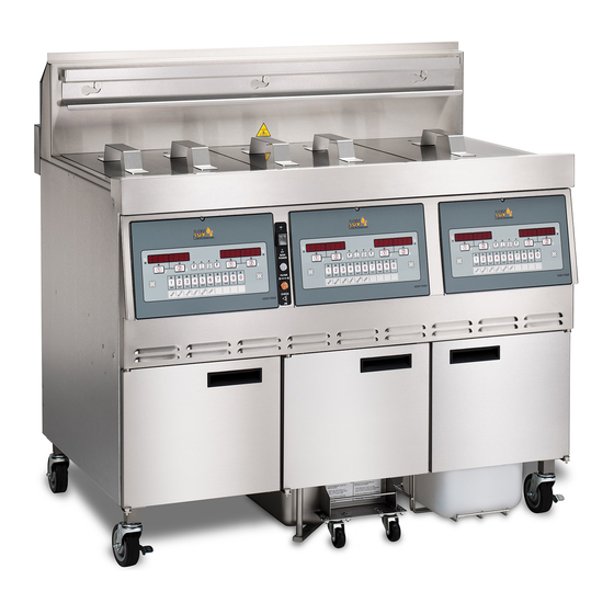
- Page 1 OPEN FRYER (Gas) REDUCED OIL CAPACITY MODEL LVG-202 LVG-203 LVG-204 R E G I S T E R W A R R A N T Y O N L I N E AT W W W. H E N N Y P E N N Y. C O M...
- Page 2 Compliance Information These are the original version controlled Henny Penny instructions for Low oil Volume Gas (LVG) model 20 number of vats 2 (LVG-202/203/204). Read these instructions completely prior to installation and operation of this appliance to ensure compliance to all required installation, operation and safety standards.
-
Page 3: Table Of Contents
TABLE OF CONTENTS Section Page Section 1. TROUBLESHOOTING ....................1-1 Introduction ....................1-1 Safety ......................1-1 Troubleshooting ....................1-2 Error Code Table .................... 1-7 Section 2. INFO, FILTER & TEMP BUTTON STATS ............... 2-1 INFO Button Stats ..................2-1 FILTER Button Stats ..................2-1 TEMP Button Stats .................. - Page 4 Section 7. MAINTENANCE SECTION (Continued) High Limit Thermocouple ................7-4 High Limit Control ..................7-5 Probe Replacement ..................7-6 7-10 Back Shroud Removal ..................7-6 7-11 Blower Replacement ..................7-7 7-12 Vacuum Switch Replacement ................. 7-7 7-13 JIB Pump Replacement .................. 7-8 7-14 Selector Valve Drive Motor Replacement ............
- Page 5 Technical Data for CE Marked Products Nominal Heat Input: Natural (I2H) = 19,8, kW (67,560 Btu/h) (Net) Natural (I2E) = 19.8 kW (67,560 Btu/h) Natural (I2E+) = 19.8 kW (67,560 Btu/h) Natural (I2L) = 19.8 kW (67,560 Btu/h) Natural (I2HS) = 19.8 kW (67,560 Btu/h) Liquid Propane (I3P) = 19,8, kW (67,560 Btu/h) Liquid Propane/Butane (I3B/P) = 19,8, kW (67,560 Btu/h) Nominal Heat Input:...
-
Page 6: Section 1. Troubleshooting
Model LVG-202, 203, 204 SECTION 1. TROUBLESHOOTING 1-1. INTRODUCTION This section provides troubleshooting information in the form of an easy to read table. If a problem occurs during the first operation of a new fryer, recheck the Installation Section of the Operator’s Manual. -
Page 7: Troubleshooting
Model LVG-202, 203, 204 1-3. TROUBLESHOOTING To isolate a malfunction, proceed as follows: Clearly define the problem (or symptom) and when it occurs. Locate the problem in the Troubleshooting table. Review all possible causes. Then, one-at-a-time work through the list of corrections until the problem is solved. - Page 8 Model LVG-202, 203, 204 Problem Cause Correction POWER SECTION With power switch in ON position, • Open circuit • Check to see that unit is plugged in • Check the breaker or fuse at supply the fryer is completely inoperative (NO POWER) •...
- Page 9 Model LVG-202, 203, 204 Problem Cause Correction HEATING OF SHORTENING SECTION (Continued) Oil will not heat (con- • Drain valve open • Close drain valve tinued) • Faulty temperature probe • Replace temerature probe • Faulty gas valve • Check gas valve Oil heating too slow •...
- Page 10 Model LVG-202, 203, 204 Problem Cause Correction OIL LEVEL SECTION (Continued) Vat is under-filled • Locations with RTI, the 3-way • The RTI system can be valve is stuck open disconnected until RTI repairs the • Filter pan needs cleaned...
- Page 11 Model LVG-202, 203, 204 DISPLAYED PROMPT SECTION “IS POT FILLED” filter • All oil did not completely return • Have manager follow prompts after a filter cycle Is JIB full? If not, fill JIB error prompt • Replace filter pad/clean pan.
- Page 12 Model LVG-202, 203, 204 1-4. ERROR CODES In the event of a control system failure, the digital display shows an error message. The message codes are shown in the DISPLAY column below. A constant tone is heard when an er- ror code is displayed, and to silence this tone, press any button.
- Page 13 Model LVG-202, 203, 204 1-4. ERROR CODES (CONTINUED) Pressure Switch failure/ hose loose Press power button to vat off and back on again, if E-20-B persists, have pressure switch checked; Draft Fan failure/ low voltage/ Flue should be open circuit if no air pressure; make sure “E-20-B”...
- Page 14 Model LVG-202, 203, 204 1-4. ERROR CODES (CONTINUED) AIF PC board not communicating Turn switch to OFF, then back to ON; if “E-60” with control PC board persists, check 1.5 amp fuse on AIF PC board on “E-60” International units only; check connector between the PC boards;...
- Page 15 Model LVG-202, 203, 204 1-10...
-
Page 16: Section 2. Info, Filter & Temp Button Stats
Model LVG-202, 203, 204 SECTION 2. INFO, FILTER & TEMP BUTTON STATS 2-1. INFO BUTTON STATS Recovery Information for each Vat/OQM Information 1. Press and release and REC shows in left display and the recovery time that oil temperature went from 250°F (121°C) to 300°F (149°C) shows in the right display. -
Page 17: Hp Info Mode
Model LVG-202, 203, 204 Set-point Temperature 2. Press twice and SP shows in the display, along with the set-point (preset) temperature of each vat. 2-4. HP INFO MODE Cook Cycles Remaining before Filtering Press and release both at the same time to enter HP Info Mode. -
Page 18: Section 3. Level 1 Programming
Model LVG-202, 203, 204 SECTION 3. LEVEL 1 PROGRAMMING Level 1 contains the following: • Modify product settings • Set the AIF clock for products • Perform the Deep Clean procedure • Fryer Setup Mode 3-1. MODIFYING PRODUCT 1. Press and hold buttons until LEVEL - 1 shows in the display, followed by ENTER CODE. - Page 19 Model LVG-202, 203, 204 8. Press and release▼ button and “TEMP” shows in the dis- 3-1. MODIFYING PRODUCT SETTINGS (CONTINUED) play, along with the preset temperature on the right side of the display. Press the product buttons to change the temperature. The temperature range is 190°F (88°C) to 380°F (193°C).
-
Page 20: Aif Clock
Model LVG-202, 203, 204 3-2. AIF CLOCK This feature allows controls to be set for periods of the day that block the automatic “Filter Now” prompts. For example, the controls could be set not interrupt with “Filter Now” prompts during the lunch rush, and during the supper rush. But, if filter-... -
Page 21: Deep Clean Mode
Model LVG-202, 203, 204 3-2. AIF CLOCK In 12-hour clock mode, there are three items on each line: the start time “XX:XX”, the A or P (am/pm) setting, and the “XX” duration. (CONTINUED) Use the ◄ and ► buttons to set these items, which flashes when the item is selected. -
Page 22: Fryer Setup
Model LVG-202, 203, 204 3-4. FRYER SETUP This mode has the same settings as seen upon initial start-up of the fryer. 1. Press and hold buttons until LEVEL - 1 shows in the display, followed by ENTER CODE. 2. Enter code 1, 2, 3, 4 (first 4 product buttons). “PRODUCT”... -
Page 24: Section 4. Level 2 Programming
Model LVG-202, 203, 204 SECTION 4. LEVEL 2 PROGRAMMING Used to access the following: • Advanced changes to product settings • Error code log • Password programming • Alert Tone/Volume • No. of cook cycles before filter is suggested • Automatic filter time 1. -
Page 25: E-Log (Error Code Log)
Model LVG-202, 203, 204 8. Press ▼ button until “FULL HT” shows in display along 4-1. ADVANCED PRODUCT SETTINGS (CONTINUED) with full heat value in seconds, which means heat is on as soon as a timer button is pressed, for a programmed length of time. -
Page 26: Passwords
Model LVG-202, 203, 204 4-3. PASSWORDS The 4-digit passwords can be changed for access to Set-Up, Usage, Level 1, Level 2, & Get Mgr.) 1. Press and hold buttons until LEVEL - 2 shows in the display, followed by ENTER CODE. -
Page 27: Filter After
Model LVG-202, 203, 204 The number of cook cycles between filtering the oil can easily 4-5. FILTER AFTER be programmed for all products. 1. Press and hold buttons until LEVEL - 2 shows in the display, followed by ENTER CODE. -
Page 28: Section 5. Level 3 Programming
Model LVG-202, 203, 204 SECTION 5. LEVEL 3 PROGRAMMING Used to access the following: • TECH RESETS-Reset Recovery Faults/Passwords to defaults • SPCL PROG-Program filter control parameters and other items • CLOCK SET-Set the time-of-day clock / calendar • DATA COMM-Data Communications, LonWorks, MMC, etc. -
Page 29: Special Programming
Model LVG-202, 203, 204 5-2. SPECIAL PROGRAMMING The Special Program Mode is used to set more detailed program- ming, such as: SP-1 • ZONE - USA or Non-USA (default setpoints) SP-2 • System Initialization SP-3 • 2nd Language: English, French, Candian- French, German, Spanish, Portuguese, Swedish, Russian, &... - Page 30 Not all Special Program Mode functions are discussed in this section. To ensure proper operation of fryer, please consult Henny Penny Corp. before changing any of these settings. For more information on these functions, contact the Service Department at 1-800-417- 8405, or 1-937-456-8405.
- Page 31 Model LVG-202, 203, 204 5-2. SPECIAL PROGRAMMING 2nd Language (SP-3) 6. Press ▼ button and “SP-3 2ND LANGUAGE” scrolls in (CONTINUED) left display. Use ◄ and ► buttons to set to: ENGLISH; FRANCAIS; CAN FREN; ESPANOL; PORTUG; DEUTSHE; SVENSKA; РУССКИИ or -NONE-.
- Page 32 Model LVG-202, 203, 204 Edit Unit Serial Number (SP-8) 11. Press ▼ button and “SP-8 S/N √ EDIT” shows in the left display. Press the right √ button to enter the unit’s serial number in the controls, using the product buttons.
- Page 33 Model LVG-202, 203, 204 5-2. SPECIAL PROGRAMMING Decal Layout (SP-9) 11. Press ▼ button and “SP-9 DECAL LAYOUT?” scrolls in the (CONTINUED) left display. The words in the right displays should match the arrow type above the buttons. EX: If the control decal shows...
-
Page 34: Clock Set
Data communications and heat controls settings are shown in Level 3 Program Mode. But, to ensure proper operation of fryer, please consult Henny Penny Corp. before changing any of these settings. For more information on these functions, contact the Service Department at 1-800-417- 8405, or 1-937-456-8405. -
Page 35: Tech Mode
Model LVG-202, 203, 204 5-5. TECH MODE The TECH Mode has self-diagnostic information, which can be used by certified technicians for troubleshooting purposes, such • Software • Fryer Type (Gas or Elec.) • Push Button Test • All On Display Test •... - Page 36 Model LVG-202, 203, 204 5-5. TECH MODE 1. To enter the TECH Mode, press and hold (CONTINUED) buttons for 5 seconds, until display shows ”LEVEL 3” followed by “ENTER CODE”. 2. Enter code 1, 1, 2, 2, 1, 1, 2, 2 (first 2 product buttons).
- Page 37 Model LVG-202, 203, 204 5-5. TECH MODE T-8 - DECIMAL PTS TEST (CONTINUED) Press any of the product buttons numerous times to view each LED across the control panel. T-17 - DIGITAL INPUTS - HDF H = HIGH LIMIT - If “H” is present, the high limit is good.
- Page 38 Model LVG-202, 203, 204 Press ▼ button and “INP E_P_” and “JL_R_DF_” shows in 5-5. TECH MODE (CONTINUED) the displays. AIF Board Inputs: E = Stop button E* = E-Stop pressed. P = Drain Pan M* = drain pan is missing.
- Page 39 Model LVG-202, 203, 204 5-5. TECH MODE T-20 - PUMPS & VALVES √ button and “VALVES” “DcRcAc” shows in displays. (CONTINUED) Press Press to open and close the drain valves. Press to open and close the return valves. Press to open and close the add valves.
-
Page 40: Stats Mode
Model LVG-202, 203, 204 5-6. STATS MODE This mode allows a technician to view advanced information on the operation of the fryer and controls. 1. To enter the TECH Mode, press and hold buttons for 5 seconds, until display shows ”LEVEL 3”, followed by “ENTER CODE”. -
Page 41: Section 6. Information Mode
Model LVG-202, 203, 204 SECTION 6. INFORMATION MODE 6-1. INFO MODE This mode gathers and stores historic information on the fryer and operator’s performance. Press and hold for 3 seconds, until *INFO* *MODE*” shows on the displays. Press ▼ or ▲ buttons to access the steps and press √... - Page 42 Model LVG-202, 203, 204 6-1. INFO MODE LAST LOAD Press √ button to select Last Load (ex: -P1- = Product 1;”L1” = (CONTINUED) or ▲ buttons to view the ▼ left, 1st product) and press following: FUNCTION DISPLAY EX: Product (Last product cooked)
-
Page 43: Preventive Maintenance
Model LVG-202, 203, 204 SECTION 7. MAINTENANCE 7-1. PREVENTIVE To ensure a long life of fryers and their components, regular MAINTENANCE maintenance should be performed. Refer to the chart below. Frequency Action Daily Maintenance Filter (See Mainte- nance Filtering Instructions Section in Operator’s Manual or PM Guide) -
Page 44: Complete Control Replacement
Model LVG-202, 203, 204 7-3. COMPLETE CONTROL 1. Remove electrical power supplied to the unit. REPLACEMENT To avoid electrical shock or property damage, move the POWER switch to OFF and disconnect main circuit breaker, or unplug cord at wall receptacle. -
Page 45: Burner Tube Removal
Model LVG-202, 203, 204 7-5. BURNER TUBE 1. Remove electrical power supplied to the unit. REMOVAL To avoid electrical shock or property damage, move the POWER switch to OFF and disconnect main circuit breaker, or unplug cord at wall receptacle. -
Page 46: High Limit Thermocouple
Model LVG-202, 203, 204 7-6. PILOT REPLACEMENT (CONTINUED) 6. Disconnect the pilot wire located in the orange rubber sleeve. 7. Using a 7/16” wrench, loosen the pilot tube from the pilot. 8. Using a 7/16” wrench loosen and remove flame sensor. -
Page 47: High Limit Control
Model LVG-202, 203, 204 7-7. HIGH LIMIT 7. Remove the pot bushing from the vat. Replace with the new THERMOCOUPLE bushing included with new part. Apply thread sealant and (CONTINUED) tighten into vat. 8. Apply thread sealant to the compression fitting. Thread into the pot bushing. -
Page 48: Probe Replacement
Model LVG-202, 203, 204 7-9. PROBE 1. Remove electrical power supplied to the unit. REPLACEMENT To avoid electrical shock or property damage, move the POWER switch to OFF and disconnect main circuit breaker, or unplug cord at wall receptacle. 2. Lower the control board (refer to the Control Board section). -
Page 49: Blower Replacement
Model LVG-202, 203, 204 7-11. BLOWER REPLACEMENT 1. Remove electrical power supplied to the unit. To avoid electrical shock or property damage, move the POWER switch to OFF and disconnect main circuit breaker, or unplug cord at wall receptacle. 2. Remove the lower back shroud (See back shroud removal). -
Page 50: Jib Pump Replacement
Model LVG-202, 203, 204 7-13. JIB PUMP 1. Remove electrical power supplied to the unit. REPLACEMENT To avoid electrical shock or property damage, move the POWER switch to OFF and disconnect main circuit breaker, or unplug cord at wall receptacle. -
Page 51: Selector Valve Drive Motor Replacement
Model LVG-202, 203, 204 7-14. SELECTOR VALVE DRIVE MOTOR REPLACEMENT 1. Remove electrical power supplied to the unit. To avoid electrical shock or property damage, move the POWER switch to OFF and disconnect main circuit breaker, or unplug cord at wall receptacle. - Page 52 Model LVG-202, 203, 204 7-14. SELECTOR VALVE DRIVE MOTOR REPLACEMENT (CONTINUED) 11. Using a 5/32 allan wrench (recommended T-Handle), loosen the 4 screws on the coupler that is clamped onto the drive tube. 12. Lift motor off of selector valve body.
- Page 53 Model LVG-202, 203, 204 20. Tighten the bolts with the 5/32 allan wrench. 7-14. SELECTOR VALVE DRIVE MOTOR REPLACEMENT (CONTINUED) •DO NOT tighten the coupler at this time •DO NOT install the shield at this time 21. Reconnect the power cord to the unit. The selector valve will run a quick calibration to find the home position.
-
Page 54: Gas Valve Replacement
Model LVG-202, 203, 204 7-15. GAS VALVE 1. Remove electrical power supplied to the unit. REPLACEMENT To avoid electrical shock or property damage, move the POWER switch to OFF and disconnect main circuit breaker, or unplug cord at wall receptacle. -
Page 55: Introduction
This section lists the replaceable parts of the Henny Penny Model LVG fryer. 8-2. GENUINE PARTS Use only genuine Henny Penny parts in your fryer. Using a part of lesser quality or substitute design may result in damage to the unit or personal injury. - Page 56 Model LVG-202, 203, 204 Recommend Parts: A=Truck Stock/B=Dist. Stock /*not shown Aug. 2012...
- Page 57 Model LVG-202, 203, 204 Item No. Part No. Description Quantity TS22-012 TRANSFORMER - AIF ............76978 FLAME SENSOR ..............2/vat A 3 75854 ASSY - SPARK IGNITOR (PILOT) ........2/vat A 4 89624-001 HIGH LIMIT CONTROL - 120V .......... 1/vat...
- Page 58 Model LVG-202, 203, 204 NON-CE GAS VALVE ASSEMBLY CE GAS VALVE ASSEMBLY Item No. Part No. Description Quantity (per assy) FP01-242 FITTING - 1/2 NPT M to 45 FLARE M ......87663-101 VALVE - GAS CONTROL - NAT - FULL ...... 1/vat 87663-102 VALVE - GAS CONTROL - NAT - SPLIT .....
- Page 59 Model LVG-202, 203, 204 Item No. Part No. Description Quantity 52224 SWITCH - POWER ............. 75860 LIGHT - INDICATOR - BLUE ........75859 LIGHT - INDICATOR - YELLOW ......------- ASSY-DOOR ............... See chart on next page 77575 CASTER- 4” W/BRAKE ..........
- Page 60 Model LVG-202, 203, 204 83774 86382 LH Door Assy RH Door Assy without Holder with Holder Model LVG-202 83774 83774 86382 LH Door Assy LH Door Assy RH Door Assy without Holder without Holder with Holder Model LVG-203 87432 83774...
- Page 61 Model LVG-202, 203, 204 Control Panel Assembly Item No. Part No. Description Quantity 97319 ASSY - CONTROL - LOV ..........1/well** 85378 DECAL - LOV MCD ..........1/control NS02-005 NUT - HEX KEPS #6-32 C ........23/control 26974 ASSY - SPEAKER ............ 1/control 83498 STUD ASSY - CONTROL PANEL COVER ....
- Page 62 Model LVG-202, 203, 204 Item No. Part No. Description Quantity B 1 ME90-008 RELAY - PUMP MOTOR - 12 VDC - 30 AMP ......85698RB PC BOARD - AIF ................79213 TRANSDUCER-PRESSURE 30 PSI ..........79596-XXXX GATEWAY PC BOARD (See chart below) ........
- Page 63 Model LVG-202, 203, 204 Located behind motor Item No. Part No. Description Quantity 73473 PUMP - OIL TOP OFF - 120V ........B 1 74583 PUMP - OIL TOP OFF - 230V ........67583 MOTOR, 1/2 HP- 50/60 Hz ..........
- Page 64 Model LVG-202, 203, 204 Filter Motor and Pump Item No. Part No. Description Quantity 151534-001 ASSY-FILTER PMP & 1/2 HP MOTOR ......67589 ASSY-FILTER PMP & 1/2 HP MOTOR ......A 1 67583 MOTOR, 1/2 HP - 50/60 Hz ..........
- Page 65 Model LVG-202, 203, 204 See Next page for parts Item No. Part No. Description Quantity 77839 MODULE- IGNITION NON CE ......2/ WELL 77602 MODULE- IGNITION CE ........2/ WELL Recommend Parts: A=Truck Stock/B=Dist. Stock / *not shown Dec. 2012...
- Page 66 Model LVG-202, 203, 204 2 Well 3 & 4 Well Aug. 2012 8-12...
- Page 67 Model LVG-202, 203, 204 2 WELL Item No. Part No. Description Quantity FP02-047 NIPPLE- 1/2 X 4 1/2 LONG ........FP01-090 ELBOW-1/2 X 90 FEMALE ........FP01-023 NIPPLE- 1/2 INCH CLOSE ........FP01-150 UNION- 1/2 THREADED ......... FP01-018 1/2 STR PIPE COUPLING ........
- Page 68 Model LVG-202, 203, 204 Item No. Part No. Description Quantity 79327 FLEXIBLE GAS LINE W/SHUT-OFF VALVE - 2 -WELL-36 IN 77668-002 FLEXIBLE GAS LINE W/SHUT-OFF VALVE - 3 -WELL-72 IN Recommend Parts: A=Truck Stock/B=Dist. Stock / *not shown Aug. 2012...
- Page 69 Model LVG-202, 203, 204 Jan. 2013 8-15...
- Page 70 COVER-REAR SHROUD LVG-202 ........86568 COVER-REAR SHROUD LVG-203 ........87558 COVER-REAR SHROUD LVG-204 ........89901 COVER- LOWER REAR LVG-202 ........86567 COVER- LOWER REAR LVG-203 ........87557 COVER- LOWER REAR LVG-204 ........79363 ASSY-CE CONT CORD & PLUG 230V .......
-
Page 71: Selector Valve
Model LVG-202, 203, 204 SELECTOR VALVE FLEX HOSES LENGTH/ PART NUMBER LVG-202 Selector Valve Port SD SR SS FD FR FS Plug 24” Plug 30” 18” 18” 18” 24” Plug 18” 18” Plug 18” 18” 18” 18” Plug Plug Plug... - Page 72 Model LVG-202, 203, 204 SELECTOR VALVE FLEX HOSES LENGTH/ PART NUMBER (CONTINUED) LVG-204 Selector Valve SSSD SSSR FSSD FSSR FFSD FFSR FFFD FFFR FFFF SSSF SSFF SFFF Port SSSS FSSS FFSS FFFS Plug 54” Plug Plug Plug 54” 54” 54”...
- Page 73 Model LVG-202, 203, 204 See previous pages for lengths and part numbers Item No. Part No. Description Quantity FP01-235 FTG-SAE ELBOW 45 DEG FLARE ........FP01-205 ELBOW- 1/2 IN NPT MALE 45 FLARE ......FP01-277 CONNECTOR-6 SAE M 6 SAE F .........
- Page 74 Model LVG-202, 203, 204 Item No. Part No. Description Quantity 76980 RACK - SPLIT VAT ............1/vat 76982 RACK - FULL VAT ............1/vat 92717 THERMOCOUPLE - HIGH LIMIT ........ 1/vat 140098 KIT- ASSY 2.5 INCH PROBE/ CAUGE ......A/R 140206 KIT-REPLACEMENT FULL POT ASSY .......
- Page 75 Model LVG-202, 203, 204 Item No. Part No. Description Quantity 03617 ACCESSORY-JUG-AUTO TOP OFF (EMPTY) ......... 1 B 2 85738 ASSY-JIB TUBE & QUICK DISC (includes items 3 & 4) ....1 85737 ASSY-INT’L. JIB TUBE & QUICK DISC (includes items 3 & 4) ..1 FP05-017 QUICK DISCONNECT - 3/8”...
- Page 76 163322 WELD ASSY-CRUMB CATCHER ......85503 WELD ASSY-FILTER WEIGHT ......03190-054 McD’s FILTER KIT (not supplied by Henny Penny)..(includes fryer cleaner, 30 filter pads, & green cleaner pads) 85519 FILTER-SECTION ............ 95842 ASSY-DRAIN PAN & CASTERS-20X (Before 01/17) ..
- Page 77 Model LVG-202, 203, 204 Fry Cap Item No. Part No. Description Quantity 03702 ACCESSORY-FRY CAP - LVG-202 ....... 03703 ACCESSORY-FRY CAP - LVG-203 ....... 1 03704 ACCESSORY-FRY CAP - LVG-204 ....... Recommend Parts: A=Truck Stock/B=Dist. Stock / *not shown Aug. 2012...
- Page 78 Model LVG-202, 203, 204 05160001 Oil Quality Monitoring (OQM) Sensor Item No. Part No. Description Quantity 154103 CLAMP, SENSOR OQM............. 154101 ASSY, OQM SENSOR & TUBE ..........154104 SEAL, SENSOR OQM ..............154102 WELD ASSY, OQM SENSOR BODY ........FP01-337 ELBOW-45 DEG 8 SAE ORB X 8 SAE ........
- Page 79 Model LVG-202, 203, 204 APPENDIX A. WIRING DIAGRAMS AND SCHEMATICS The legend below helps in identifying the components of the wiring diagrams on the following wiring diagrams. May 2016...
- Page 80 Model LVG-202, 203, 204 May 2016...
- Page 81 Model LVG-202, 203, 204 May 2016...
- Page 82 Model LVG-202, 203, 204 May 2016...
- Page 83 Model LVG-202, 203, 204 May 2016...
- Page 84 Model LVG-202, 203, 204 May 2016...
- Page 85 Model LVG-202, 203, 204 May 2016...
- Page 86 Model LVG-202, 203, 204 May 2016...
- Page 87 Model LVG-202, 203, 204 May 2016...
- Page 89 Henny Penny Corporation P.O.Box 60 Eaton,OH 45320 1-937-456-8400 1-937-456-8402 Fax Toll free in USA 1-800-417-8417 1-800-417-8434 Fax *FM06-048-B* www.hennypenny.com Henny Penny Corp., Eaton, Ohio 45320, Revised 01/22/18...
Need help?
Do you have a question about the LVG-202 and is the answer not in the manual?
Questions and answers