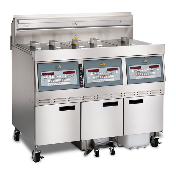
Henny Penny LVE-102 Technical Manual
Split vat & full vat open fryers – electric
Hide thumbs
Also See for LVE-102:
- Operator's manual (60 pages) ,
- Operation manual (59 pages) ,
- Manual (22 pages)

Subscribe to Our Youtube Channel
Related Manuals for Henny Penny LVE-102


Summary of Contents for Henny Penny LVE-102
- Page 1 Henny Penny Split Vat & Full Vat Open Fryers – Electric Model LVE-102 Model LVE-103 Model LVE-104 TECHNICAL MANUAL...
-
Page 3: Table Of Contents
Model LVE-102, 103, 104 TABLE OF CONTENTS Section Page Section 1. TROUBLESHOOTING ....................1-1 Introduction ....................1-1 Safety ......................1-1 Troubleshooting ....................1-2 Error Code Table .................... 1-7 Section 2. INFO, FILTER & TEMP BUTTON STATS ............... 2-1 INFO Button Stats ..................2-1 FILTER Button Stats .................. - Page 4 Model LVE-102, 103, 104 TABLE OF CONTENTS Section Page Section 7. MAINTENANCE SECTION (Continued) Temperature Probe Replacement ..............7-8 Oil Channel Clean-Out ................... 7-10 7-10 Element Safety Switch ................... 7-11 7-11 Contactors ....................... 7-12 7-12 Solenoid Valves ....................7-14 7-13 Drain Valve Actuators ..................
-
Page 5: Section 1. Troubleshooting
Model LVE-102, 103, 104 SECTION 1. TROUBLESHOOTING 1-1. INTRODUCTION This section provides troubleshooting information in the form of an easy to read table. If a problem occurs during the first operation of a new fryer, recheck the installation per the Installation Section of the Operator’s manual. Before troubleshooting, always recheck the operation pro- cedures per Section 3 of the Operator’s manual. -
Page 6: Troubleshooting
Model LVE-102, 103, 104 1-3. TROUBLESHOOTING To isolate a malfunction, proceed as follows: 1. Clearly define the problem (or symptom) and when it occurs. Locate the problem in the Troubleshooting table. Review all possible causes. Then, one-at-a-time work through the list of corrections until the problem is solved. - Page 7 Model LVE-102, 103, 104 Problem Cause Correction POWER SECTION • • With power switch in Open circuit Check to see that unit is plugged in ON position, the fryer • is completely inoperative Check the breaker or fuse at supply box •...
- Page 8 Model LVE-102, 103, 104 Problem Cause Correction HEATING OF SHORTENING SECTION (Continued) Oil will not heat • • Drain valve open Close drain valve (Continued) • • Possible faulty temperature probe Replace temperature probe • • Faulty contactor Check contactor per maintenance section on contactors •...
- Page 9 Model LVE-102, 103, 104 Problem Cause Correction OIL LEVEL SECTION Oil foaming or boiling over vat • Water in oil • At end of a Cook Cycle, drain and clean vat; add fresh oil • Improper or bad oil • Use recommended oil • Improper filtering...
- Page 10 Model LVE-102, 103, 104 Problem Cause Correction FILTER MOTOR SECTION • Tighten all filter line connec - Filter motor runs but • Filter line connections pumps oil slowly loose tions • Drain pan o-rings damaged • Install new o-rings or missing • Change filter paper or pad • Filter paper or pad clogged Filter motor will not run •...
- Page 11 Model LVE-102, 103, 104 1-4. ERROR CODES In the event of a control system failure, the digital display shows an error message. The message codes are shown in the DISPLAY column below. A constant tone is heard when an er- ror code is displayed, and to silence this tone, press any button.
- Page 12 Model LVE-102, 103, 104 1-4. ERROR CODES (Continued) DISPLAY CAUSE CORRECTION “E-31” Elements are up Lower elements back down Programming failure Turn switch to OFF, then back to ON; if display “E-41” , shows any of these error codes, re-initialize the “E-46”...
-
Page 13: Section 2. Info, Filter & Temp Button Stats
Model LVE-102, 103, 104 SECTION 2. INFO, FILTER & TEMP BUTTON STATS 2-1. INFO BUTTON STATS Recovery Information for each Vat/OQM Information 1. Press and release and REC shows in left display and the recovery time that oil temperature went from 250°F (121°C) to 300°F (149°C) shows in the right display. -
Page 14: Hp Info Mode
Model LVE-102, 103, 104 each vat. Set-point Temperature 2. Press twice and SP shows in the display, along with the set-point (preset) temperature of each vat. Cook Cycles Remaining before Filtering 2-4. HP INFO MODE Press and release both at the same time to enter HP Info Mode. -
Page 16: Section 3. Level 1 Programming
Model LVE-102, 103, 104 SECTION 3. LEVEL 1 PROGRAMMING Level 1 contains the following: • Modify product settings • Set the AIF clock for products • Perform the Deep Clean procedure • Fryer Setup Mode 3-1. MODIFYING PRODUCT 1. Press and hold... - Page 17 Model LVE-102, 103, 104 3-1. MODIFYING PRODUCT 8. Press and release button and “TEMP” shows in the SETTINGS (Continued) display, along with the preset temperature on the right side of the display. Press the product buttons change the temperature. The temperature range is 190°F (88°C) to 380°F (193°C).
-
Page 18: Aif Clock
Model LVE-102, 103, 104 3-2. AIF CLOCK This feature allows the controls to be set for periods of the day that block the automatic “Filter Now” prompts. For ex- ample, the controls could be set not interrupt with “Filter Now”... -
Page 19: Deep Clean Mode
Model LVE-102, 103, 104 3-2. AIF CLOCK In 12-hour clock mode, there are three items on each line: the start time “XX:XX”, the A or P (am/pm) setting, and the “XX” (Continued) duration. Use the buttons to set these items, which flashes when the item is selected. To set a new start time setting, use the product buttons, to enter the new value. -
Page 20: Fryer Setup
Model LVE-102, 103, 104 3-4. FRYER SETUP This mode has the same settings as seen upon initial start-up of the fryer. 1. Press and hold buttons until LEVEL - 1 shows in the display, followed by ENTER CODE. 2. Enter code 1, 2, 3, 4 (first 4 product buttons). “PROD- UCT”... - Page 21 Model LVE-102, 103, 104...
-
Page 22: Section 4. Level 2 Programming
Model LVE-102, 103, 104 SECTION 4. LEVEL 2 PROGRAMMING Used to access the following: • Advanced changes to product settings • Error code log • Password programming • Alert Tone/Volume • No. of cook cycles before filter is suggested • Automatic filter time 1. Press and hold buttons until LEVEL - 2 4-1. -
Page 23: E-Log (Error Code Log)
Model LVE-102, 103, 104 4-1. ADVANCED PRODUCT 8. Press button until “FULL HT” shows in display along SETTINGS (Continued) with full heat value in seconds, which means the heat is on as soon as a timer button is pressed, for programmed length of time. -
Page 24: Passwords
Model LVE-102, 103, 104 4-3. PASSWORDS The 4-digit passwords can be changed for access to Set-Up, Usage, Level 1, Level 2, & Get Mgr.) 1. Press and hold buttons until LEVEL - 2 shows in the display, followed by ENTER CODE. -
Page 25: Filter After
Model LVE-102, 103, 104 The number of cook cycles between filtering the oil can easily 4-5. FILTER AFTER be programmed for all products. 1. Press and hold buttons until LEVEL - 2 shows in the display, followed by ENTER CODE. 2. Enter code 1, 2, 3, 4 (first 4 product buttons). “PROD” and “COMP” show in the displays. 3. Press button 4 times and “FILR AFTR”... -
Page 26: Section 5. Level 3 Programming
Model LVE-102, 103, 104 SECTION 5. LEVEL 3 PROGRAMMING Used to access the following: • TECH RESETS-Reset Recovery Faults/Passwords to defaults • SPCL PROG-Program filter control parameters and other items • CLOCK SET-Set the time-of-day clock / calendar • DATA COMM-Data Communications, LonWorks, MMC, etc • HEAT CTRL-Program heat algorithm control parameters • TECH MODE-Control of outputs, display & button tests, etc. -
Page 27: Special Programming
Model LVE-102, 103, 104 5-2. SPECIAL PROGRAMMING The Special Program Mode is used to set more detailed program- ming, such as: SP-1 • ZONE - USA or Non-USA (default setpoints) SP-2 • System Initialization SP-3 • 2nd Language: English, French, Candian- French, German, Spanish, Portuguese, Swedish, Russian, &... - Page 28 Not all Special Program Mode functions are discussed in this section. To ensure proper operation of fryer, please consult Henny Penny Corp. before changing any of these settings. For information on these functions, contact the Service Department at 1-800-417- 8405, or 1-937-456-8405.
- Page 29 Model LVE-102, 103, 104 5-2. SPECIAL PROGRAMMING 2nd Language (SP-3) 6. Press button and “SP-3 2ND LANGUAGE” scrolls in (Continued) left display. Use buttons to set to: ENGLISH; FRANCAIS; CAN FREN; ESPANOL; PORTUG; DEUTSHE; SVENSKA; РУССКИИ or -NONE-. By setting a second language in the controls, 2 languages...
- Page 30 Model LVE-102, 103, 104 5-2. SPECIAL PROGRAMMING Edit Unit Serial Number (SP-8) 11. Press button and “SP-8 S/N √ EDIT” shows in left (Continued) display. Press the right √ button to enter the unit’s serial number in the controls, using the product buttons. “STD” and “CUST” show in the right displays. Press the √ button under the “STD” and the first 2 letters of the serial number is the...
-
Page 31: Clock Set
Data communications and heat controls settings are shown in Level 3 Program Mode. But, to ensure proper operation of fryer, please consult Henny Penny Corp. before changing any of these settings. For more information on these functions, contact Service Department at 1-800-417- 8405, or 1-937-456-8405. -
Page 32: Tech Mode
• Total Initialization Not all Tech Mode functions are discussed in this section. To ensure proper operation of fryer, please consult Henny Penny Corp. before changing any of these settings. For more information on these functions, contact Service Department at 1-800-417- 8405, or 1-937-456-8405. - Page 33 Model LVE-102, 103, 104 5-5. TECH MODE (Continued) 1. To enter the TECH Mode, press and hold buttons for 5 seconds, until display shows ”LEVEL 3”, followed by “ENTER CODE”. 2. Enter code 1, 1, 2, 2, 1, 1, 2, 2 (first 2 product buttons). “A. TECH” & “RESETS” show in the displays.
- Page 34 Model LVE-102, 103, 104 5-5. TECH MODE (Continued) T-8 - LED’S TEST Press any of the product buttons numerous times to view each LED across the control panel. T-17 - DIGITAL INPUTS - HDE H = HIGH LIMIT - If “H” is present, the high limit is good.
- Page 35 Model LVE-102, 103, 104 5-5. TECH MODE (Continued) If the right control is unplugged, then the left control would show “1 OF 2” instead of “1 OF 3”. Press button and “INP E_P_” and “JL_R_DT_” shows in the displays. AIF Board Inputs: E = Stop button E* = E-Stop pressed.
- Page 36 Model LVE-102, 103, 104 5-5. TECH MODE (Continued) T-20 - PUMPS & VALVES √ button and “VALVES” “DcRc” shows in displays. Press Press to open and close the drain valves. Press to open and close the return valves. “DcRc” means valves are closed, “DoRo” means valves are open.
-
Page 37: Stats Mode
Model LVE-102, 103, 104 5-6. STATS MODE This mode allows a technician to view advanced information on the operation of the fryer and controls. 1. To enter the TECH Mode, press and hold buttons for 5 seconds, until display shows ”LEVEL 3”, followed by “ENTER CODE”. -
Page 38: Section 6. Information Mode
Model LVE-102, 103, 104 SECTION 6. INFORMATION MODE 6-1. INFO MODE This mode gathers and stores historic information on fryer and operator’s performance. Press and hold for 3 seconds, unitil *INFO* *MODE*” shows on the displays. buttons to access steps and press √ button Press to view the statistics within each step. - Page 39 Model LVE-102, 103, 104 6-1. INFORMATION LAST LOAD Press √ button to select Last Load (ex: -P1- = Product 1;”L1” MODE (Continued) = left, 1st product) and press buttons to view the following: FUNCTION DISPLAY EX: Product (Last product cooked) PRODUCT...
-
Page 40: Maintenance Hints
Model LVE-102, 103, 104 SECTION 7. MAINTENANCE 7-1. INTRODUCTION This section provides checkout and replacement procedures, for various parts of fryer. Before replacing any parts, refer to Troubleshooting Section to aid you in finding the cause of the malfunction. 7-2. MAINTENANCE HINTS 1. A multimeter will help you to check electric components. -
Page 41: Control Panel And Menu Card Replacement
Model LVE-102, 103, 104 7-4. CONTROL PANEL & Should the control panel become inoperative, or the menu card MENU CARD needs changed, follow these instructions. REPLACEMENT 1. Remove electrical power supplied to the vat. To avoid electrical shock or property damage, move the power switch to OFF and disconnect main circuit breaker, or unplug cord at wall receptacle. -
Page 42: High Temperature Limit Control
Model LVE-102, 103, 104 7-5. HIGH TEMPERATURE This is a safety, manual reset control, which senses the temper- LIMIT CONTROL ature of the oil. If the oil temperature exceeds 425°F (218°C), this switch opens and shuts off heat to the vat. When the oil temperature drops to a safe operation limit (15 to 20 minutes), manually reset the control by pressing the reset button. - Page 43 Model LVE-102, 103, 104 7-5. HIGH TEMPERATURE Replacement (continued) LIMIT CONTROL (Continued) 3. Using a Phillip’s-head screwdriver, remove 3 screws securing the high limit to the bracket. 4. Use the lift tool and lift the hinged element from the vat.
- Page 44 Model LVE-102, 103, 104 7-5. HIGH TEMPERATURE Replacement (continued) LIMIT CONTROL (Continued) 8. Using a Phillip’s-head screwdriver, remove the screws securing the capillary bulb to the upper element brackets. 9. Remove high limit bulb from element and carefully straighten the capillary tube and pull the high limit control from the rear of the unit.
- Page 45 Model LVE-102, 103, 104 7-5. HIGH TEMPERATURE Replacement (continued) LIMIT CONTROL 14. While holding tool in fully depressed position, inspect high (Continued) limit switch reset button position within the bracket. a. If any red plastic of reset button can be seen, adjust bracket in or out using needle nose pliers so the angle of the assembly matches the angle of the plunger.
-
Page 46: Breakers
Model LVE-102, 103, 104 7-6. BREAKERS There are two breakers on electric fryers. To reset the breaker, open the left door and push-up on the plunger of each breaker. To avoid electrical shock or property damage, move the power switch to OFF and disconnect main circuit breaker, or unplug cord at wall receptacle. -
Page 47: Main Power Switch
Model LVE-102, 103, 104 7-7. MAIN POWER SWITCH This is a covered rocker switch, which in the ON position, sends power to all the controls and filter motor. To avoid electrical shock or property damage, move the power switch to OFF and disconnect main circuit breaker, or unplug cord at wall receptacle. - Page 48 Model LVE-102, 103, 104 7-8. TEMPERATURE PROBE Checkout: REPLACEMENT (Continued) To avoid electrical shock or property damage, move the power switch to OFF and disconnect main circuit breaker, or unplug cord at wall receptacle. 1. Remove control panel and hinge it down.
-
Page 49: Oil Channel Clean-Out
Model LVE-102, 103, 104 7-8. TEMPERATURE PROBE 5. Follow probe installation instructions below: REPLACEMENT (Continued) Excess force will damage temperature probe. Hand-tighten nut and then 1/2 turn with a wrench. 6. Connect new temperature probe to the 2 fryer connections. -
Page 50: Element Safety Switch
Model LVE-102, 103, 104 7-10. ELEMENT SAFETY This switch cuts power to the element when the element is raised. SWITCH If a constant “E-31” “HEATING ELEMENTS ARE UP”, is shown on the display, when the elements are lowered into the vat, check the element safety switch. -
Page 51: Contactors
Model LVE-102, 103, 104 7-11. CONTACTORS The open fryer requires two switching, 24V contactors per vat: a primary and a heat contactor. The primary contactor energiz- es (contacts close) any time the main power switch is in the ON position, and the temperature of the shortening is below 420°... - Page 52 Model LVE-102, 103, 104 7-11. CONTACTORS (Continued) 4. With power reapplied and in a heat-up mode, check the power going to both contactor coils. Power should be going to both contactors. If no voltage is found going into the primary contactor coil, check wiring, high limit, and element switch.
-
Page 53: Solenoid Valves
Model LVE-102, 103, 104 7-12. SOLENOID VALVES Each vat has a solenoid plumbed-into the oil return lines. They are normally closed, but open when power is supplied, such as, the controls are filling the vats. To avoid electrical shock or property damage, move the power switch to OFF and disconnect main circuit breaker, or unplug cord at wall receptacle. -
Page 54: Drain Valve Actuators
Model LVE-102, 103, 104 7-12. SOLENOID VALVES 5. Remove elbow from solenoid stem assembly and attach it (Continued) to new solenoid, using pipe sealent on the threads. 6. Remove the conduit from fryer and pull the coil assembly from the fryer. -
Page 55: Filter Pump & Motor
Model LVE-102, 103, 104 7-14. FILTER PUMP & MOTOR The 2 most common causes for a fryer not to pump oil are that the pump is clogged, or the thermal overload switch has been tripped on the motor. The pump and motor is located on the rear of the fryer. - Page 56 Model LVE-102, 103, 104 7-14. FILTER PUMP & MOTOR (Continued) To avoid electrical shock or property damage, move the power switch to OFF and disconnect main circuit breaker, or unplug cord at wall receptacle. Motor Removal: 1. Remove JIB from fryer.
- Page 57 Model LVE-102, 103, 104 7-14. FILTER PUMP & MOTOR (Continued) 7. Using a 7/16 in. wrench, remove 4 bolts securing the motor to the motor bracket and pull the pump and motor assembly from fryer. 8. Pull pump and motor out, from front of fryer, across the JIB shelf. To replace pump on motor: 1. Using a 1/2 in. wrench, remove the 2 bolts securing pump...
-
Page 58: Jib Pump
Model LVE-102, 103, 104 T his pump keeps the vats filled (Auto Top-Off) 7-15. JIB PUMP Replacement: To avoid electrical shock or property damage, move the power switch to OFF and disconnect main circuit breaker, or unplug cord at wall receptacle. 1. Remove the right side panel. -
Page 59: Transformers
Model LVE-102, 103, 104 7-17. TRANSFORMERS These components drop the line voltage to low voltage com- poents such as, control board, AIF board and contactors. Checkout: 1. Perform Power Section troubleshooting,paragraph 1-3. To avoid electrical shock or property damage, move power switch to OFF and disconnect main circuit breaker, or unplug cord at wall receptacle. -
Page 60: Filter Motor Relay
Model LVE-102, 103, 104 7-17. TRANSFORMERS Checkout (Continued): (Continued) 11. If control panel still does not display, replace panel with a known good control panel. If problem follows control panel, replace panel. Replacement: 1. Disconnect electrical power and using a 5/16” socket, remove nuts securing transformer and remove transformer. -
Page 61: Drain Pan Switch
Model LVE-102, 103, 104 7-19. DRAIN PAN SWITCH This switch closes when the drain pan is pushed properly in place under the fryer. If the drain pan is not properly in place, or the drain switch is faulty, display prompts such as, “CHECK... -
Page 62: Filter And Jib Lights
Model LVE-102, 103, 104 7-20. FILTER AND JIB LIGHTS Replacement: To avoid electrical shock or property damage, move the power switch to OFF and disconnect main circuit breaker, or unplug cord at wall receptacle. 1. Remove control panel. 2. Locate wires to light and cut wires. -
Page 63: Oil Level Probes
Model LVE-102, 103, 104 7-21. OIL LEVEL PROBES The oil level probes (left & right-see photo at left) monitor the oil level by temperature differences. If they becomes disabled, the display shows: “E-18A”= left probe; “E18-B”= right probe; “E18C”= both. - Page 64 Model LVE-102, 103, 104 7-21. OIL LEVEL PROBES (Continued) 5. Using a 1/2” wrench, remove nut on compression fitting, and remove the temperature probe from the vat. 6. Using a terminal extractor, remove probe terminals from the connector and pull remove probe from unit. 7. Place the nut and new ferrule on new temperature probe and insert temperature probe into the compression fitting.
-
Page 65: Electric Heating Elements
Model LVE-102, 103, 104 7-21. OIL LEVEL PROBES 9. Connect new temperature probe to connector and fasten (Continued) connector onto control panel. 10. Replace control panel and reconnect power to vat. 11. Fill vat by pressing and holding a button until *FILTER* *MENU* shows in display. - Page 66 Model LVE-102, 103, 104 7-22. ELECTRIC HEATING ELEMENTS (Continued) 5. Remove 2 screws and front and rear capillary brackets if replacing left heater of a full vat or a split vat heater. 6. Using a Phillip’s-head screwdriver, or screw gun, remove 9 screws and rear panel.
- Page 67 Model LVE-102, 103, 104 7-22. ELECTRIC HEATING ELEMENTS (Continued) 11. Place new heater element near vat, pass lead wires through pivot housing, lower heater into vat, align holes of heater retainer plate with the holes in the pivot housing and install 2 screws.
-
Page 68: Check Valve
OFF and disconnect main circuit breaker, or unplug cord at wall receptacle. 1. Disassemble fittings as necessary, remove old valve. 2. Apply Loctite Primer (Henny Penny part no. MS01-572) Apply Primer Here internal threads of both the inlet and outlet of new valve. - Page 69 Model LVE-102, 103, 104 7-30 Dec. 2009...
-
Page 70: Section 8. Parts Information
Model LVE-102, 103, 104 SECTION 8. PARTS INFORMATION 8-1. INTRODUCTION This section lists the replaceable parts of the Henny Penny Model LVE fryer. 8-2. GENUINE PARTS Use only genuine Henny Penny parts in your fryer. Using part of lesser quality or substitute design may result in damage to the unit or personal injury. - Page 71 Model LVE-102, 103, 104 (Behind Control Panel) Item No. Part No. Description Quantity B 1 ME90-008 RELAY - PUMP MOTOR- 12 VDC - 30 AMP ........A 2 140082 KIT-TRANSFORMER-120V/75VA-SN: BH1002029 & Below .. 1/vat A 2 84391 TRANSFORMER-120V/75VA-SN: BH1002030 & Above .. 1/vat A 2 140061 KIT-TRANSFORMER-230V/75VA-SN: BH1002033 & Below .. 1/vat...
- Page 72 Model LVE-102, 103, 104 (Left Side Panel Removed) Item No. Part No. Description Quantity 51065 EMC FILTER PCB - CE ............EF02-125 BREAKER-PUSH BUTTON RESET - 15 AMP .... 79596-XXXX GATEWAY - PCB (not shown - see chart below) .....
- Page 73 Model LVE-102, 103, 104 Right Side Panel Removed Item No. Part No. Description Quantity ASSY - DRAIN VALVE ACTUATOR ............ 1/vat 76783 73647 SOLENOID - ASCO - 120V (JIB Solenoids) ..........74582 SOLENOID - ASCO - 230V (JIB Solenoids) ..........
- Page 74 Model LVE-102, 103, 104 DRAIN EXTENSION QUANTITY SELECTION CHART P/N 74553 P/N 77305 P/N 80191 MODEL QUANTITY QUANTITY QUANTITY LVE-102 DS LVE-102 FF LVE-102 FR LVE-102 FS LVE-102 LS LVE-102 SD LVE-102 SF LVE-102 SR LVE-102 SS LVE-103 DSF LVE-103 DSS LVE-103 FFF...
- Page 75 Model LVE-102, 103, 104 Optional RTI Plumbing Feb. 2011...
- Page 76 Model LVE-102, 103, 104 Item No. Part No. Description Quantity CONTACTOR - 24V COIL (Heat Contactor) ...... 1/vat 78753 CONTACTOR - 24V COIL (Primary Contactor) .... 1/vat 29509 SWITCH - ELEMENT LIFT .......... 1/vat 18227 KIT - HIGH LIMIT - 425 F ............ 1/vat...
- Page 77 Model LVE-102, 103, 104 Item No. Part No. Description Quantity 77842 HANGER-BASKET - LVE-102 .......... 77709 HANGER-BASKET - LVE-103 .......... 77934 HANGER-BASKET - LVE-104 .......... 52224 SWITCH - POWER............. 75860 LIGHT - INDICATOR - BLUE ........... 75859 LIGHT - INDICATOR - YELLOW ........
- Page 78 Model LVE-102, 103, 104 DOOR PART NUMBERS FOR UNITS BUILT BEFORE MAY 3, 2010 89895 89898 LH Door Assy RH Door Assy with Holder with Label Model LVE-102 89895 89898 87041 LH Door Assy RH Door Assy RH Door Assy...
- Page 79 ASSY - SEAM COVER - LVE-103 ........83730 ASSY - SEAM COVER - LVE-104 ........76563 WELD ASSY - SEAM COVER - LVE-102 ...... 76500 WELD ASSY - SEAM COVER - LVE-103 ...... 77613 WELD ASSY - SEAM COVER - LVE-104 ......
- Page 80 Model LVE-102, 103, 104 FULL VAT ELEMENT ASSEMBLY 10 11 Item No. Part No. Description Quantity 1 SC01-076 SCREW #8-32 X 1/4 PH THD S .......... 2/vat PLATE - FRONT CAPILLARY .......... 1/vat 75819 PLATE - REAR CAPILLARY .......... 1/vat 75818 4 SC01-074 SCREW #10-32 X 1/2 PH THD S ........... 4/vat HOUSING - ELEMENT PIVOT .......... 1/vat...
- Page 81 Model LVE-102, 103, 104 SPLIT VAT ELEMENT ASSEMBLY Item No. Part No. Description Quantity 1 SC01-076 SCREW #8-32 X 1/4 PH THD S .......... 2/vat PLATE - FRONT CAPILLARY .......... 1/vat 75819 PLATE - REAR CAPILLARY .......... 1/vat 75818 4 SC01-074 SCREW #10-32 X 1/2 PH THD S ........... 2/vat HOUSING - ELEMENT PIVOT .......... 1/vat 74209 WELD ASSY - HI LIMIT RESET PIN ........ 1/vat...
- Page 82 Model LVE-102, 103, 104 Control Panel Assembly Item No. Part No. Description Quantity 96972 ASSY - CONTROL - LOV ..........DECAL - LOV MCD .......... 1 /control 75660 NUT - HEX KEPS #6-32 C ........ 2 3/control NS02-005 ASSY - SPEAKER ............ 1 /control 26974 STUD ASSY - CONTROL PANEL COVER .... 1 /control...
- Page 83 82673 ASSY-DRAIN PAN COVER ........76259 WELD ASSY-CRUMB CATCHER ......76179 WELD ASSY-FILTER WEIGHT ......03190-054 McD’s FILTER KIT (not supplied by Henny Penny)..(includes fryer cleaner, 30 filter pads, & green cleaner pads) 76375 FILTER-SECTION ............ 82672 WELD ASSY-DRAIN PAN ........52487 CASTER - FILTER PAN ........
- Page 84 Model LVE-102, 103, 104 Item No. Part No. Description Quantity 03617 ACCESSORY-JUG-AUTO TOP OFF (EMPTY) ........1 B 2 78992 ASSY-JIB TUBE & QUICK DISC (Includes items 3 & 4) ...... 1 80490 ASSY-INT’L. JIB TUBE & QUICK DISC (Includes items 3 & 4) ..1...
- Page 85 COVER - REAR SHROUD - LVE-103 ......81050 COVER - REAR SHROUD - LVE-104 ......2 78316 COVER - SUPPORT - POWER CORD - LVE-102 ..78314 COVER - SUPPORT - POWER CORD - LVE-103 ..79177 COVER - SUPPORT - POWER CORD - LVE-104 ..
- Page 86 Model LVE-102, 103, 104 Oil Disposal Plumbing-France Item No. Part No. Description Quantity 80752 FITTING-QUICK COUPLE FEMALE........2 FP01-219 NIPPLE-1IN NPT X 4-1/2 LG BI ........... 3 SC06-075 U-BOLT 3/8-16 FOR 1-1/2 DIA. (included nuts)....80745 BRKT-FRENCH DRAIN TUBE MTG ........5 NS02-002 NUT KEPS 1/4-20 C ..............80808 STUD ASSY-ADJ OIL DSPL BRACKET ......
- Page 87 Model LVE-102, 103, 104 Oil Disposal Plumbing-Australia Item No. Part No. Description Quantity 16239 ELBOW STREET 90 DEGREE ........2 FP01-023 NIPPLE - 1/2 INCH CLOSE BLACK......A 3 74469 VALVE-1/2 CHECK ............4 FP02-018 1/2 STR PIPE COUPLING CONDUIT ......5 FP01-112 1/2 NPT FEMALE PIPE TEE BI ........6 FP01-205 ELBOW-1/2 IN NPT MALE 45 FLARE ......7 FP01-217 COUPLE-REDUCE 1 F X 1/2F BI .........
- Page 88 Model LVE-102, 103, 104 Drain Valve Linkage Parts - Standard Vat Item No. Part No. Description Quantity 1 PN01-031 PIN - LOCKING WEDGE - 1/4 x 1-1/4...... 1/vat VALVE - DRAIN ............ 1/vat 79590 HANDLE - PIVOT - DRAIN .......... 1/vat 73994 PIVOT - BUSHING - ACTUATOR ........ 1/vat 74568 PIN - ACTUATOR - CLEVIS ......... 1/vat...
- Page 89 Model LVE-102, 103, 104 Drain Valve Linkage Parts - Fish Vat Item No. Part No. Description Quantity VALVE-DRAIN ............... 1/vat 79590 STOP-PIVOT DRAIN HANDLE ........ 1/vat 74626 EXTENSION-DRAIN ............. 1/vat 74553 WELD ASSY-FISH DRAIN ROD ........ 1/vat 77405 STUD ASSY-DR ROD BRKT-FISH VAT ....... 1/vat...
- Page 90 Model LVE-102, 103, 104 Fry Cap Item No. Part No. Description Quantity 03618 ACCESSORY-FRY CAP - LVE-102 ....... 03619 ACCESSORY-FRY CAP - LVE-103 ....... 1 03620 ACCESSORY-FRY CAP - LVE-104 ....... 8-21 May 2009...
- Page 91 Model LVE-102, 103, 104 Filter Return Line Assembly Item No. Part No. Description Quantity 77523 TUBE-SUCTION 18 IN L DORMONT ......2 FP01-206 CONNECTOR-3/8 NPT FEM 45 FLARE ..... 3 FP01-029 REDUCER 1/2NPT M-3/8NPT F SS ......77259 BRACKET-PLUG AND PLAY ........77248 ADAPTER-TUBE END ..........6 FP01-204 NIPPLE-3/8 NPT X 6IN L BLACK ........
- Page 92 Model LVE-102, 103, 104 Filter Motor and Pump Item No. Part No. Description Quantity A 1 67583 MOTOR, 1/2 HP - 50/60 Hz ..........A 2 17476 SEAL KIT ................ B 3 17437 PUMP ASSEMBLY ............SC01-132 SCREW, Pump Cover ..........17451 COVER, Pump ............
- Page 93 Model LVE-102, 103, 104 05160002 Oil Quality Monitoring (OQM) Sensor Item No. Part No. Description Quantity 154103 CLAMP, SENSOR OQM............. 154101 ASSY, OQM SENSOR & TUBE ..........154104 SEAL, SENSOR OQM ..............154102 WELD ASSY, OQM SENSOR BODY ........FP01-307 ADPT-SAE8 ORBM 1/2 M JIC45 FLR ........
- Page 94 Model LVE-102, 103, 104 APPENDIX A. WIRING DIAGRAMS AND SCHEMATICS A-1. WIRING DIAGRAMS AND APPENDIX A contains the wiring diagrams and schematics to SCHEMATICS support the LVE-100 series fryers. May 2016...
- Page 95 Model LVE-102, 103, 104 May 2016...
- Page 96 Model LVE-102, 103, 104 May 2016...
- Page 97 Model LVE-102, 103, 104 May 2016...
- Page 98 Model LVE-102, 103, 104 May 2016...
- Page 99 Model LVE-102, 103, 104 May 2016...
- Page 100 Model LVE-102, 103, 104 May 2016...
- Page 101 Model LVE-102, 103, 104 May 2016...
- Page 102 Model LVE-102, 103, 104 May 2016...
- Page 103 Model LVE-102, 103, 104 A-10 May 2016...
- Page 104 Model LVE-102, 103, 104 A-11 May 2016...
- Page 105 Model LVE-102, 103, 104 A-12 May 2016...
- Page 106 Model LVE-102, 103, 104 A-13 May 2016...
- Page 107 Model LVE-102, 103, 104 A-14 May 2016...
- Page 108 Model LVE-102, 103, 104 A-15 May 2016...
- Page 109 Model LVE-102, 103, 104 A-16 May 2016...
- Page 110 Model LVE-102, 103, 104 A-17 May 2016...
- Page 111 Model LVE-102, 103, 104 A-18 May 2016...
- Page 112 Model LVE-102, 103, 104 A-19 May 2016...
- Page 113 Model LVE-102, 103, 104 May 2016 A-20...
- Page 114 Model LVE-102, 103, 104 May 2016 A-21...
- Page 115 Model LVE-102, 103, 104 May 2016 A-22...
Need help?
Do you have a question about the LVE-102 and is the answer not in the manual?
Questions and answers