
Related Manuals for Security Tronix ST-PTZ480-22X


Summary of Contents for Security Tronix ST-PTZ480-22X
- Page 1 INSTALLATION MANUAL © ST-PTZ480-22X High-Speed Intelligent PTZ Dome Color Camera Copyright North American Cable Equipment, Inc. V2.0 5/1412...
-
Page 2: Package Contents
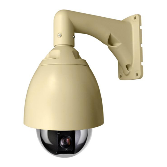
One installation manual. PRODUCT DESCRIPTION The ST-PTZ480-22X is a professional grade intelligent dome color camera with pan, tilt and zoom (PTZ) capability and 480TVL of resolution. The camera’s full digital design allows the saving of all settings in non-volatile memory. Its 128 preset positions, 4 tours, left-right scans and pattern record capability provides versatility for professional installations. -
Page 3: Unpacking And Handling
24. Long-Focus Speed Proportion 25. Included 24VAC power supply 26. Communication RS485(+/-) 27. Camera Menu Operation 28. IP66 for Outdoor Use 95% 29. Operating Humidity 30. Heater Operation 42ºF on; 57ºF off 31. Operating Temperature -40ºF - 122ºF 32. Video Connection BNC coaxial 33. -
Page 4: Camera Setup
d. Do not install the camera near a magnetic field or a high-power motor. e. Do not mount the camera near a radiator or heater. The installation site and material must fully support the weight of the product. g. Only use a dry cloth to clean the camera. If there is dirt that is difficult to remove wipe gently with a mild detergent. -
Page 5: Wiring Connections
To select the baud rate set switches 3 and 2 on the System Setup DIP Switch as described above. Camera Module Selection The ST-PTZ480-22X uses a purpose-made camera module although various other camera modules may be compatible with the unit. The DIP switches on the camera module’s PCB board are factory set for the... -
Page 6: Functions And Operation
Make an RS485 connection between the camera and the PTZ controller. Ensure the connections at the PTZ controller and camera have the same polarities. 6. FUNCTIONS and OPERATION Basic Operation After powering up the ST-PTZ480-22X’s version number, High Speed Dome communication protocol, baud rate and address will be Ver:2.20 shown on the monitor. - Page 7 Menu Operation Call preset 95 to enter the menu setup. The main menu will be shown on the screen. Note the following symbols: Indicates current working cursor Indicates current activated cursor ► Indicates there is a sub-menu after the current menu The menu content is only changed under activated status.
- Page 8 To change exposure mode under “Exp Mode” press OPEN to enter the exposure mode “ Exp Mode”. Move the joystick up or down to change menu. Once done the menu becomes the exposure modes. Confirmation of an exposure mode selection – Exp Mode Auto “...
- Page 9 For WB Mode Setup – Under ”WB mode” press OPEN to activate the WB mode menu after “WB mode”. Move the joystick up or down to change the setup. which the menu turns to The order of parameters on the right will be Auto, Manual, Outdoor, Indoor, ATW and OPW. For R Gain Setup –...
- Page 10 Camera Mode Save: The 3 menus under “Camera Mode Save” are Normal previous saved camera modes. Move the cursor to a camera mode and press OPEN. will change to Night and return to after 1 second after which the Camera Mode Exec:...
- Page 11 Shortcut Key The Shortcut Key Menu is found under the Main Menu. Shortcut keys allow the association of a certain function with a corresponding preset allowing for quick and convenient function selection. Open Menu Open Menu Opens the menu Auto Flip Auto Flip Auto Flip Reference...
- Page 12 Leisure Time If the Leisure (dwell) Time reaches the previously set value after manual operation the unit will automatically run according to Self Act (except when Self Act is set to “Nothing”). If the parameter in Self Act is “Home Place” the user must ensure that “Home Place” is on. The value of Leisure Time can be set from 1 to 240.
-
Page 13: Troubleshooting
Note: The maximum relay output is 24VAC @1A. Once in the Alarm Mode/Alarm Set Sub-Menu press OPEN. The symbol turns to . The parameters can now be changed. Press OPEN to confirm or CLOSE to cancel. The symbol will return to . Degree The Degree Menu is found under the Main Menu and is used to display the pan degree on the monitor. - Page 14 APPENDIX A CAMERA ADDRESS SETTING USING 8-DIGIT DIP SWITCH SW2 CAM ID ∶ ∶ ∶ ∶ ∶ ∶ V2.0 5/1412...
- Page 15 V2.0 5/1412...
Need help?
Do you have a question about the ST-PTZ480-22X and is the answer not in the manual?
Questions and answers