Table of Contents
Advertisement
Quick Links
Advertisement
Table of Contents

Related Manuals for Security Tronix ST-PTZIR650-23


Summary of Contents for Security Tronix ST-PTZIR650-23
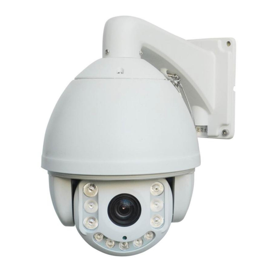
- Page 1 INSTALLATION MANUAL ST-PTZIR650-23 High Speed Intelligent Dome PTZ Color Camera...
-
Page 2: Warnings And Cautions
Copyright North American Cable Equipment, WARNINGS AND CAUTIONS WARNING TO REDUCE THE RISK OF FIRE OR ELECTRIC SHOCK, DO NOT EXPOSE THIS PRODUCT TO RAIN OR MOISTURE. DO NOT INSERT ANY METALLIC OBJECTS THROUGH VENTILATION GRILLS OR OPENINGS ON THE EQUIPMENT. CAUTION EXPLANATION OF GRAPHICAL SYMBOLS The lighting flash with arrowhead symbol, within an equilateral triangle, is intended to... - Page 3 PRECAUTIONS: Persons without technical qualifications should not attempt to operate this dome device before reading this manual thoroughly. Remove any power to the dome before attempting any operations or adjustments inside the dome cover to avoid potential damage to the mechanism. ...
-
Page 4: Important Safeguards
IMPORTANT SAFEGUARDS 1. Read these instructions before attempting installation or operation of this dome. 2. Keep these instructions for future reference. 3. Heed all warnings and adhere to electrical specifications. Follow all instructions. 4. Clean only with non abrasive dry cotton cloth, lint free and approved acrylic cleaners. 5. -
Page 5: Product Contents
1 Product Contents IR Speed dome Wall mount bracket Power supply Screws kit User manual... - Page 6 1.2 Specification Horizontal Rotation 0.02°-200°/s Speed Tilt Rotation Speed 0.02°-100°/s Horizontal Rotation 360° Range Tilt Rotation Range 93° Auto Flip Horizontal 180°, Vertical 90° Auto control IR LED A-B Scan User programmable A-B Scan Speed 1-64 levels setting available 360° Scan Speed 1-64 levels setting available Dwell Preset 5-60s interval...
- Page 7 1.3 Performance Features PWM function. Intelligent IR illumination & power consumption is variable, dependent upon the zoom factor. 3D allocation. The pan and zoom functions are performed simultaneously for faster target acquisition. Supported Protocols. Pelco-D/P; Others on special request. ...
- Page 8 1.4 Function Description Auto-adaptive to Protocol and Module The dome can auto-adapt to multiple protocols and many camera modules without changing the DIP switchs. 3D Allocation Allow the camera to operate both the pan and tilt simultaneously while recalling presets, for faster operation.
- Page 9 BLC Back Light Compensation (Not available on this model) If a bright backlight is present, the target in the picture may appear dark or as a silhouette. The BLC function can enhance the target in the center of the picture; the dome uses the center of the picture to adjust the iris.
-
Page 10: Installation
2 Installation 2.1 DIP Switch Settings 2.1.1 Preparation Before installation, make sure that the protocol, baud rate and address code used by the product is fully consistent with the control system. Corresponding DIP switch settings can be seen below. The access plate for the DIP switches is located just above the camera lens opening on the outside of the camera: NOTE: It is much easier to set the communication parameters using the on-screen menu rather... - Page 11 2.1.3 Baud Rate Settings The 4th and 5th “Function” (FUN) DIP Switches set the Baud rate. Factory-default setting is 2400bps. This is the baud rate which SecurityTronix recommends for most installations. Baud rates: 1200bps, 2400bps, 4800bps, 9600bps selectable 2.1.4 RS-485 Bus Matching Resistance The 8 DIP switch of FUN SW2 is to select the matching resistor.
- Page 12 2.2 Bracket Dimensions 2.2.1 Included Wall Mounted Bracket 2.2.2 Optional Corner Mounted Bracket...
- Page 13 2.3 Installation of Brackets. 2.3.1 Wall Mounted Fig 1 Installation conditions: This wall mounted dome can be used on walls whose thickness and sturdiness should be enough to install expansion bolt outdoors, or be used with an electrical box or mounted to a stud indoors.
- Page 14 Fig 3 2.4 Connection RS485 Connection Before connecting, please turn off the power and read the instructions of all connected devices carefully. Fig 24 3. Instruction 3.1 Power Up Action IR SPEED DOME When initializing the system, the OSD screen shown at left will PROTOCOL PELCO-D/P appear after 2 seconds.
- Page 15 IR SPEED DOME This screen shows that the initialization of the pan/tilt motors has completed. PROTOCOL PELCO-D/P COMM 2400.N.8.1 DOME ID MODULE VERSION OVER TILT OVER POWER ON IR SPEED DOME Power up self-testing has completed. PROTOCOL PELCO-D/P COMM 2400.N.8.1 DOME ID MODULE BT-367...
- Page 16 Preset Points For SETTING, CALLING and DELETING presets, please refer to the instructions provided with your PTZ controller. Remark: Some preset points are reserved for special functions. See below. 3.3 Special Function Presets The following presets are predefined for special functions. CALL the corresponding preset using your controller to activate the function: PREST FUNCTION...
-
Page 17: Osd Menu
4 OSD Menu 4.1 Menu Index... - Page 18 4.1 System Information SYSTEM INFORMATION <MAIN MENU> PROTOCOL: Displays the protocol of the dome. Baud rate: represents the communication <SYSTEM INFORMATION> <DOME SET> Information; 2400 is the baud rate, which <CAM SET> can be changed via the DIP switches or <IR SET>...
-
Page 19: Scan Speed
To write the preset, enter the command on your PTZ <PRESET> controller for “Call preset 1”. To cancel the write PRESET NO operation, enter the command on your PTZ CALL PRESET controller for “Call preset 2”. <SET PRESET> Because some presets are used to operate special functions, PRESET 1: SAVE they can’t be set and called normally. -
Page 20: Call Pattern
PATTERN ID: Factory default is 1. Select the pattern to be edited. There are 4 patterns. <PATTERN> CALL PATTERN: Call (run) the pattern which is PATTERN ID currently selected. CALL PATTERN <PATTERN SET> <PATTERN SET> EXIT The figure at left shows the screen when the camera is ready to record a pattern. - Page 21 4.2.6 Other HOME POS: There are 13 possible actions: preset 1-8, A-B scan, 360° scan, guard tour preset, pattern, no action. HOME TIME: The dome camera runs home <DOME SET> position after a period of idle time. The range is 1-60 <PRESET>...
- Page 22 4.4 IR SET <IR SET> IR MODE: Mode has auto, small light on, big light on, manual, and off selectable IR MODE AUTO TESTING TIME: 2-15s selectable TESTING TIME ILLUMINATION ON ILLUMINATION ON: Its range is 0-25 level. In the IR IR SWITCH ZOOM mode of auto, when the “ILLUMINATION ON”...
- Page 23 set and press the ‘right’ key to enter the edit screen. 2: Use the up and down keys to adjust the present value, and press the right key to enter and move to the next adjustment. The item being changed will blink. When it blinks, operate the right key again to exit the editing the schedule.
-
Page 24: Anti-Lightning, Anti-Surge
Anti-lightning, Anti-surge This product is air discharge and lightning protected with TVS tube technology, which can effectively prevent transient lightning below 3000 volts, surge and damages caused by other types of pulse signals. However, necessary protective measures should be made on the premise of ensuring electrical safety for outdoor installation according to the situation : ·Signal transmission line must be at least 50 meters away from any high-voltage equipment or high voltage cables. -
Page 25: Clean Transparent Cover
Clean Transparent Cover In order to assure a clear image of dome, the clear dome should be cleaned regularly. ● Be careful when cleaning and hold the outer ring to avoid directly touching the dome. ● Please use a soft dry cloth or other alternatives to wipe internal and external surfaces. ●... - Page 26 Address Code Mapping Table SW1 DIP Switch sets the dome address.. The following is a dome address code mapping table to set PELCO_D: Switch Settings Address SW1-1 SW1-2 SW1-3 SW1-4 SW1-5 SW1-6 SW1-7 SW1-8 ---- ---- ---- ---- ---- ---- ---- ----...
- Page 27 The following is a dome address code mapping table to set PELCO_P: Switch Settings Address SW1-1 SW1-2 SW1-3 SW1-4 SW1-5 SW1-6 SW1-7 SW1-8 ---- ---- ---- ---- ---- ---- ---- ----...
- Page 28 TROUBLESHOOTING a. No picture after applying power – (i) check all plugs and cables are connected to the proper connectors: (ii) ensure your power supply is providing the correct voltage and enough current. b. The picture has ripples – (i) Check to see if the power supply is experiencing AC ripple. If so, a filter may be required.
Need help?
Do you have a question about the ST-PTZIR650-23 and is the answer not in the manual?
Questions and answers