Table of Contents
Advertisement
Quick Links
Advertisement
Table of Contents

Related Manuals for Security Tronix ST-IP4FB


Summary of Contents for Security Tronix ST-IP4FB
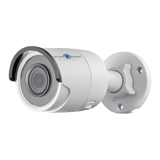
- Page 1 ST-IP4FB QUICK START GUIDE www.nacebrands.com www.securitytronix.com...
-
Page 2: Regulatory Information
ST-IP4FB·Quick Start Guide About this Manual This Manual includes instructions for using and managing the product. Pictures, charts, images and all other information hereinafter are for description and explanation only. The information contained in the Manual is subject to change, without notice, due to firmware updates or other reasons. - Page 3 ST-IP4FB·Quick Start Guide Please take attention that changes or modification not expressly approved by the party responsible for compliance could void the user’s authority to operate the equipment. FCC compliance: This equipment has been tested and found to comply with the limits for a Class B digital device, pursuant to part 15 of the FCC Rules.
- Page 4 ST-IP4FB·Quick Start Guide EU Conformity Statement This product and - if applicable - the supplied accessories too are marked with "CE" and comply therefore with the applicable harmonized European standards listed under the EMC Directive 2014/30/EU, the RoHS Directive 2011/65/EU...
-
Page 5: Safety Instruction
ST-IP4FB·Quick Start Guide Safety Instruction These instructions are intended to ensure that user can use the product correctly to avoid danger or property loss. The precaution measure is divided into “Warnings” and “Cautions” Warnings: Serious injury or death may occur if any of the warnings are neglected. - Page 6 ST-IP4FB·Quick Start Guide ● Do not connect several devices to one power adapter as adapter overload may cause over-heating or a fire hazard. ● Please make sure that the plug is firmly connected to the power socket. When the product is mounted on wall or ceiling, the device shall be firmly fixed.
- Page 7 ST-IP4FB·Quick Start Guide ● Do not place the camera in extremely hot, cold (the operating temperature shall be-30°C ~+60°C, or -40°C ~ +60°C if the camera model has an “H” in its suffix), dusty or damp locations, and do not expose it to high electromagnetic radiation.
- Page 8 ST-IP4FB·Quick Start Guide Table of Contents 1 Appearance Description ..............8 Overview of Type I Bullet Camera ........8 Overview of Type II Bullet Camera ........ 10 1.2.1 Resetting the Camera ......... 11 1.2.2 Setting the WPS Protocol........12 Overview of Type III Bullet Camera ....... 14 2 Installation ..................
-
Page 9: Appearance Description
ST-IP4FB·Quick Start Guide 1 Appearance Description Overview of Type I Bullet Camera Figure 1-1 Type I Bullet Camera... - Page 10 ST-IP4FB·Quick Start Guide Table 1-1 Description Description Description Mounting Base Lens Back Case Sun Shield Front Case Power Cable Reset Button GND Screw 10/100M Self-adaptive Ethernet Interface Type I camera does not support the function of Wi-Fi or SD card.
-
Page 11: Overview Of Type Ii Bullet Camera
ST-IP4FB·Quick Start Guide Overview of Type II Bullet Camera Figure 1-2 Type II Bullet Camera... -
Page 12: Resetting The Camera
ST-IP4FB·Quick Start Guide Table 1-2 Description Description Description Mounting Base Memory Card Slot Back Case Power Supply Interface 10/100M Self-adaptive Sun Shield Ethernet Interface Lens PoE Cable Adjusting Nut GND Screw WPS/RESET Button This type of bullet camera supports PoE power supply. You can ... -
Page 13: Setting The Wps Protocol
ST-IP4FB·Quick Start Guide WPS/RESET Figure 1-3 WPS/RESET Button 1.2.2 Setting the WPS Protocol A wireless router with the WPS function is required to enable the WPS function of the camera. Refer the steps below. Steps: Enable the WPS function of your router. Refer to the operation guide of your router for detailed procedures. - Page 14 ST-IP4FB·Quick Start Guide WPS/RESET Figure 1-4 WPS/RESET Button You can also press the WPS button on the camera first and then enable the WPS function on the router to establish the connection. But the WPS function of the router must be turned on within 120s right after pressing the WPS/RESET button on the camera.
-
Page 15: Overview Of Type Iii Bullet Camera
ST-IP4FB·Quick Start Guide Overview of Type III Bullet Camera Figure 1-5 Type III Bullet Camera... - Page 16 ST-IP4FB·Quick Start Guide Table 1-3 Description Description Description Mounting Base Grounding Screw 10/100M Self-adaptive Back Case Ethernet Interface (PoE) Front Case Power Supply (DC 12V) Lens Memory Card Slot Sun Shield Reset Button This type of bullet camera supports PoE power supply. You can ...
-
Page 17: Installation
ST-IP4FB·Quick Start Guide 2 Installation Before you start: ● Make sure the device in the package is in good condition and all the assembly parts are included. ● The standard power supply is 12V DC or 24V AC, please make sure your power supply matches with your camera. -
Page 18: Installation Of Memory Card
ST-IP4FB·Quick Start Guide Installation of Memory Card Type II and Type III camera support memory card function. Follow the steps to mount and unmount a memory card. Steps: 1. Unscrew the cover on back case to expose memory card slot. -
Page 19: Installation Of The Bullet Camera
ST-IP4FB·Quick Start Guide 3. (Optional)To unmount the memory card, push to get it ejected. 4. Screw the cover back to the camera. Installation of the Bullet Camera Both wall mounting and ceiling mounting are suitable for the bullet camera. Wall mounting will be taken as an example in this section. - Page 20 ST-IP4FB·Quick Start Guide 2. Route the corresponding cables. 3. Secure the camera to the wall with the supplied Screws. Figure 2-4 Secure the Camera to the Ceiling 4. Connect the cables and power on the camera to view live view image.
- Page 21 ST-IP4FB·Quick Start Guide 1). Loosen the adjusting nut. 2). Adjust the pan direction [0° to 360°]. 3). Adjust the tilt direction [0° to 90°]. 4). Rotate the camera [0° to 360°] to adjust the lens to the surveillance angle. 5). Tighten the adjusting nut to complete the installation.
- Page 22 ST-IP4FB·Quick Start Guide Components Network Plug Waterproof Endcap Waterproof Rubber Gasket Lock Nut Network Cable from Router/Switch Align the snap and notch. i. Insert into ⑤ ④ ii. Secure with ⑥ ④ Camera Switch/Router Figure 2-7 Water-proof Accessory Installation...
- Page 23 ST-IP4FB·Quick Start Guide Steps: Feed the plugless network cable ⑦ through the lock nut ⑥, waterproof rubber gasket ⑤ (rubber gasket inset ridge must face waterproof endcap), and the water-proof endcap ④ in order. Crimp an RJ-45 network plug ③onto the end of the cable, taking care to insert the twisted pairs of wires in correct order.
-
Page 24: Setting The Network Camera Over The Lan
ST-IP4FB·Quick Start Guide 3 Setting the Network Camera over the Note: You shall acknowledge that the use of the product with Internet access might be under network security risks. For avoidance of any network attacks and information leakage, please strengthen your own protection. -
Page 25: Activating The Camera
ST-IP4FB·Quick Start Guide Activating the Camera You are required to activate the camera first by setting a strong password for it before you can use the camera. Activation via Web Browser, Activation via SADP, and Activation via Client Software are all supported. We will take activation via SADP software and Activation via Web Browser as examples to introduce the camera activation. -
Page 26: Activation Via Sadp Software
ST-IP4FB·Quick Start Guide Figure 3-3 Activation Interface(Web) 3. Create a password and input the password into the password field. STRONG PASSWORD RECOMMENDED– We highly recommend you create a strong password of your own choosing (using a minimum of 8 characters, including... - Page 27 ST-IP4FB·Quick Start Guide Get the SADP software from the supplied disk or the official website, and install the SADP according to the prompts. Follow the steps to activate the camera, please refer to the User Manual of Network Camera for other two activation methods.
-
Page 28: Modifying The Ip Address
ST-IP4FB·Quick Start Guide STRONG PASSWORD RECOMMENDED– We highly recommend you create a strong password of your own choosing (using a minimum of 8 characters, including upper case letters, lower case letters, numbers, and special characters) in order to increase the security of your product. - Page 29 ST-IP4FB·Quick Start Guide Steps: 1. Run the SADP software. 2. Select an activate device. 3. Change the device IP address to the same subnet with your computer by either modifying the IP address manually or checking the checkbox of Enable DHCP.
- Page 30 ST-IP4FB·Quick Start Guide Note: You can enable the STGO2 service for the device during activation. Refer to Chapter 5.1 for detailed information. 4. Input the admin password and click Modify to activate your IP address modification. The batch IP address modification is supported by the SADP. Please...
-
Page 31: Accessing Via Web Browser
ST-IP4FB·Quick Start Guide 4 Accessing via Web Browser System Requirement: Operating System: Microsoft Windows XP SP1 and above version CPU: 2.0 GHz or higher RAM: 1G or higher Display: 1024×768 resolution or higher Web Browser: Internet Explorer 8.0 and above version, Apple Safari 5.0.2 and above version, Mozilla Firefox 5.0 and above version and... - Page 32 ST-IP4FB·Quick Start Guide 4. Click Login. Figure 4-1 Login Interface 5. Install the plug-in before viewing the live video and managing the camera. Please follow the installation prompts to install the plug-in. Note: You may have to close the web browser to finish the installation of the plug-in.
-
Page 33: Enable Stgo2 Service On Camera
ST-IP4FB·Quick Start Guide 5 Operating via Guarding Vision/STGO2 Purpose: STGO2 is an application for mobile devices. With the App, you can view live image of the camera, receive alarm notification and so on. Note: STGO2 service is not supported by certain camera models. - Page 34 ST-IP4FB·Quick Start Guide “Privacy Policy” Service” Figure 5-1 Verification Code Setting (SADP) Note: The verification code is required when you add the camera to STGO2 app. 3. Click and read "Terms of Service" and "Privacy Policy". 4. Confirm the settings.
- Page 35 ST-IP4FB·Quick Start Guide Steps: 1. Access the camera through web browser. Refer to Chapter 4. 2. Enter platform access configuration interface: Configuration > Network > Advanced Settings > Platform Access Guarding Vision dev.guardingvision.com Figure 5-2 Platform Access Configuration (Web) 3. Select Platform Access Mode as Guarding Vision.
-
Page 36: Stgo2 Setup
ST-IP4FB·Quick Start Guide 5.2 STGO2 Setup Steps: 1. Download and install the STGO2 app by searching “STGO2” in App Store or Google Play 2. Launch the app and register for a STGO2 user account. 3. Log in STGO2 app after registration. - Page 37 ST-IP4FB·Quick Start Guide You can find the QR code on the camera or on the cover of the Quick Start Guide of the camera in the package. Figure 5-4 Scan QR Code Note: If the QR code is missing or too blur to be recognized, you can also...
-
Page 38: Initializing The Memory Card
ST-IP4FB·Quick Start Guide Initializing the Memory Card Steps: Check the memory card status by tapping on the Storage Status in the Device Settings interface. If the memory card status displays as Uninitialized, tap to initialize it. The status will then change to Normal. You can then start recording any event triggered video in the camera such as motion detection. - Page 39 SECURITYTRONIX 2-Year Limited Fixed Camera Warranty Securitytronix. (the "Company") warrants to the Original Purchaser that the Fixed Camera is free from defects in workmanship or material under normal use. This warranty starts on the date of shipment of the hardware to the Original Purchaser. During the warranty period, the Company agrees to repair or replace, at its sole option, without charge to Original Purchaser, any defective component in the Fixed Camera.
Need help?
Do you have a question about the ST-IP4FB and is the answer not in the manual?
Questions and answers