
Related Manuals for Security Tronix ST-PTZIR480-22X


Summary of Contents for Security Tronix ST-PTZIR480-22X
- Page 1 INSTALLATION MANUAL© ST-PTZIR480-22X High-Speed Intelligent Dome IR PTZ Color Camera Copyright North American Cable Equipment, Inc.
-
Page 2: Package Contents
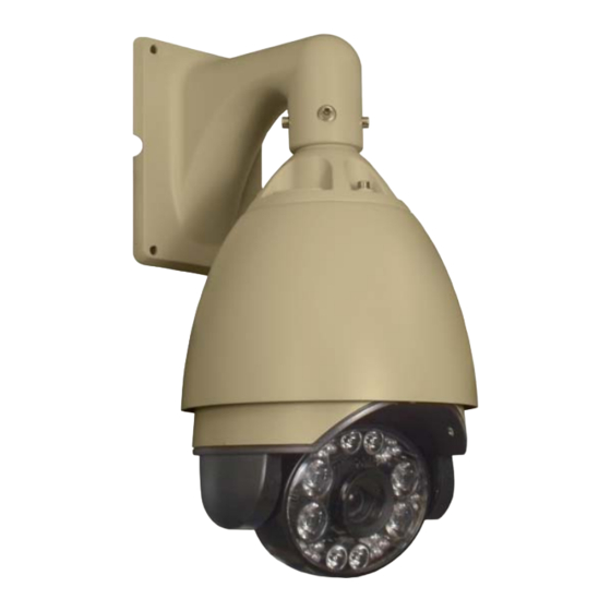
One installation manual. PRODUCT DESCRIPTION The ST-PTZIR480-22X is a professional grade infrared intelligent dome color camera with pan, tilt and zoom (PTZ) capability and 480TVL resolution. The camera’s non-volatile digital memory allows the saving of all settings. Its 200 preset positions provide versatility for cruise routes and tour functions. The ST-PTZIR480-22X’s mechanical design permits continuous horizontal 360°... -
Page 3: Specifications
SPECIFICATIONS ST-PTZIR480-22X Specifications (Typical) 1. Image Sensor Samsung SDM-270 with ¼” SONY CCD 2. Resolution 480TVL 3. Lens Auto Iris; F=3.5 to 94.5mm; 22X Optical Zoom, 10X Digital Zoom 4. Illumination 0.1 Lux 5. Pan Range 360º continuous 6. Tilt Rotation Range 0º... - Page 4 Dimensions 4 1/8” 4 1/8” 6 1/8” 3 ¾” 5 ½” 10 1/8” 6” Wall Mount Dimension 7 ¾” 5 ¼” 5 ½” 6” 6 ½” Picture 2...
-
Page 5: Unpacking And Handling
INSTALLATION AND OPERATION This symbol is intended to alert the user to the presence of important operating and maintenance (servicing) instructions. This symbol is intended to alert the user to the presence of uninsulated “dangerous voltage” within the product’s enclosure that may be of sufficient magnitude to constitute a risk of electrical shock. -
Page 6: Mechanical Inspection
b. Feed the cable assembly up through the smaller end of the mount and out the rear opening. c. Assemble the camera dome to the mounting arm using the 4 supplied allen-head cap screws and allen wrench. 2. MECHANICAL INSPECTION Inspect the entire camera for shipping damage. -
Page 7: Camera Setup
4. CAMERA SETUP BAUD RATE & PROTOCOL SETUP DIP Switch Settings Baud rate Setting SW2(B7~B8) Protocol Setting SW2(B1~B2)... -
Page 8: Dome Address Setup
DOME ADDRESS SETUP System Setup DIP Switch SW1 ON = 1 OFF = 0... - Page 9 V2.0 7-31-12...
-
Page 10: Wiring Connections
5. WIRING CONNECTIONS 6. FUNCTIONS and OPERATION Menu Operation Several functions can be accessed directly without using the camera’s on screen menu display. Note the following dedicated preset functions: Special Use Preset Numbers Call PRESET 95 ―― Enter into main OSD menu Call PRESET 96 ――... - Page 11 Menu Guide SYSTEM SETTING → DOME ID TITLE LANGUAGE SELECT CHANGE PASSWORD FACTORY DEFAULT SYSTEM RESTART SYSTEM INFOMATION MAIN MENU 【SYSTEM SETTING】 CAMERA PARAMETERS 【CAMERA PARAMETERS】 → 【LENS PARAMETER】 【PAN TILT SETTING】 【EXPOSURE MODE】 【WHITE BALANCE】 【DISPLAY 【BACKLIGHT MODE】 PANTILT SETTING →...
-
Page 12: Title Setting
Main Menu Function Setting Main menu 【SYSTEM SETTING】 【CAMERA PARAMETERS 】 【PAN TILT SETTING】 【DISPLAY System Setting MAIN MENU SYSTEM SETTING → DOME ID 【SYSTEM SETTING】 TITLE 【CAMERA PARAMETERS LANGUAGE SELECT: 】 ENGLISH 【PAN TILT SETTING】 CHANGE PASSWORD 【DISPLAY FACTORY DEFAULT CONFIGURATION】... - Page 13 Notes: 20 characters can be set. Characters include: 0-9、A-Z、 :<>-. Other text-entry menus follow this same procedure. LANGUAGE SELECT Procedure: Call preset 95 to enter the main menu. Use the up/down PTZ controls to choose [SYSTEM SETTING] and press [OPEN] to confirm the selection.
- Page 14 Under [SYSTEM SETTING] choose [SYSTEM INFORMATION] and press [OPEN] to confirm the selection. The dome’s present system information will be shown on the screen。 CAMERA PARAMETERS MAIN MENU CAMERA PARAMETERS 【SYSTEM SETTING】 → 【LENS PARAMETER 【CAMERA 】 PARAMETERS】 【EXPOSURE MODE】 【WHITE BALANCE】...
- Page 15 Call preset 95 to enter the main menu. Use the up/down PTZ controls to choose [CAMERA PARAMETERS] and press [OPEN] to confirm the selection, then enter [LENS PARAMETER] menu. Under [LENS PARAMETER] choose [FOCUS LIMIT] and press [OPEN] to confirm the selection and enter focus limit set.
-
Page 16: White Balance Menu
• AGC (Auto Gain Control): This is set individually. There are 16 settings from -3dB through 28dB. • DIGI-SLOW SHUTTER: This can be turned either on or off. Turning this ON allows the camera to increase gain by slowing down the shutter digitally. •... - Page 17 Use this setting to help compensate for lighting conditions where there is a strong light visible behind the object you are trying to observe with the camera. CAMERA PARAMETERS BACKLIGHT MODE 【LENS PARAMETER → BACK LIGHT MODE : 】 【EXPOSURE MODE】...
-
Page 18: Joystick Recover
and enter auto flip set. Use Up/down P/T to select and change this function to ON or OFF. Press the [OPEN] key to save and exit. Press the [CLOSE] key to exit directly without saving. • JOYSTICK RECOVER ALL: When ALL is selected, both the focus and iris will return to automatic operation after any joystick command is received from the camera. -
Page 19: Pantilt Setting
The IR LEDs can be set to switch from low power to high power when the zoom lens is zoomed to a certain amount. For example, setting this to “3X” will change the LEDs to the higher power setting when the lens is zoomed to 3X optical magnification or more. Procedure: Call preset point 95 to enter the main menu. -
Page 20: Sequence Setup
Preset Number Setting Procedure: 1. Call preset point 95 to enter the main menu. 2. Use Up/Down P/T to choose [PANTILT SETTING] and press [OPEN] to confirm the selection and enter preset set menu. 3. Under [PANTILT SETTING] choose the [PANTILT SETTING] sub-menu and press [OPEN] to confirm the selection. -
Page 21: Edit Sequence
Procedure: Call preset point 95 to enter the main menu. Use the Up/Down cursor to choose [PANTILT SETTING], press [OPEN] to confirm the selection and enter sequence set menu. Under [PANTILT SETTING] choose [SEQUENCE SETUP] and press [OPEN] to confirm the selection. -
Page 22: Auto Scan Setup
selection and enter pan set menu. Under [PANTILT SETTING] choose [PATTERN SETUP] and press [OPEN] to enter route recording mode. Under [PATTERN SETUP] choose [RECORD NEW PATTERN] and press [OPEN] to enter mode route recording setting. Press [OPEN] and pattern recording will begin immediately. “Recording Mode Route” will be shown on the screen. -
Page 23: Home Action
Adjusts the L/R scan speed. The speed range is adjustable from 1 to 64. Procedure: Call preset point 95 to enter the main menu. Move cursor to choose [PANTILT SETTING] choose [AUTOSCAN SETUP] and press [OPEN] to confirm the selection to enter scan function set item. Under [AUTOSCAN SETUP] choose [DEFAULT SPEED] item and press [OPEN] to confirm the selection to enter default scan speed set item. - Page 24 10. Press the [OPEN] key to save and exit. Press the [CLOSE] key to exit directly without saving. INFORMATION DISPLAY CONFIGURATION This menu sets whether or not various information is displayed within the camera’s video output and if so, the time duration of the display. MAIN MENU DISPLAY CONFIGURATION 【SYSTEM SETTING】...
-
Page 25: Alarms Setup
The camera supports 2 alarm inputs and 2 alarm outputs. When an alarm input is triggered, the following actions can be executed: • An alarm input trigger can cause the dome to immediately go to any preset for surveillance. • Either alarm output channel relay can activate external alarm equipment. -
Page 26: Alarm Linkage
ALARM LINKAGE This function is used to select which action is taken by the camera when an alarm input is triggered. E.g., Auto Scan 1 thru 4,Preset Point 1 thru 200, Sequence 1 thru 4 etc. Procedure: Call preset point 95 to enter the main menu. Use the Up/Down cursor to choose [ALARMS SETUP] and press [OPEN] to confirm the selection and enter Alarms Setup. -
Page 27: Troubleshooting
TROUBLESHOOTING a. No picture after applying power – (i) check all plugs and cables are connected to the proper connectors: (ii) ensure your power supply is providing the correct voltage and enough current. b. The picture has ripples – (i) Check to see if the power supply is experiencing AC ripple. If so, a filter may be required.
Need help?
Do you have a question about the ST-PTZIR480-22X and is the answer not in the manual?
Questions and answers