
Related Manuals for Security Tronix ST-PTZIR530-36


Summary of Contents for Security Tronix ST-PTZIR530-36
- Page 1 INSTALLATION MANUAL ST-PTZIR530-36 IP66 Rated High-Speed Intelligent Dome PTZ IR Color Camera Copyright North American Cable Equipment, Inc. V1.0 12/15/11...
-
Page 2: Table Of Contents
TABLE O F C ONTENTS PACKAGE C ONTENTS ........................3 PRODUCT D ESCRIPTION......................3 SPECIFICATIONS..........................3 INSTALLATION A ND O PERATION .................... 4 UNPACKING a nd H ANDLING......................4 ... -
Page 3: Package C Ontents
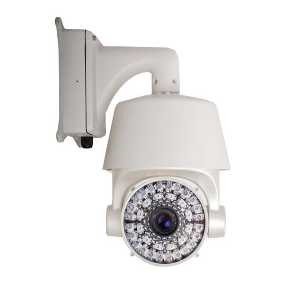
PACKAGE C ONTENTS This package contains: One ST-PTZIR530-36 high-speed intelligent dome color camera. One mounting bracket with mounting hardware. One installation manual. PRODUCT D ESCRIPTION The ST-PTZ530-36 is an IP66 rated professional grade intelligent dome color camera with pan, tilt and zoom (PTZ) capability of 530TVL using a 3.4mm to 122.4mm F1.6-F4.5 zoom... -
Page 4: Installation A Nd O Peration
INSTALLATION A ND O PERATION This symbol is intended to alert the user to the presence of important operating and maintenance (servicing) instructions. This symbol is intended to alert the user to the presence of uninsulated “dangerous voltage”... -
Page 5: Camera S Etup
h. This camera uses AC power of 100 ~ 240 volts at 0.5A. Using a DC or other incorrect power supply or source will damage the camera. Only qualified installers are allowed to install, test and disassemble the camera. The camera is a low voltage product. If installed outdoors proper safety and lightning grounding are required in addition to surge protection. -
Page 6: Camera Address Set Up
Protocol Switch 1 Switch 2 Switch 3 PELCO-D PELCO-P Reserved … … … Baud Rate Switch 4 Switch 5 9600 4800 2400 Reserved Camera Address Set Up SW1 uses all of the 8-bit switches to set up to 255 camera addresses. The 1 bit is the lowest and the 8 bit is the highest. - Page 7 Install the camera dome to the bracket using the four hexagon screws. It is advisable to apply a waterproof sealant to the joint gap where the camera dome joins the bracket. Attach the mounting template to the location where the camera is to be mounted. Drill holes according to the template and install the mounting bolts.
- Page 8 Remove two screws from the power box and open it. Thread the power cable through the waterproof head on the left and the RS485 and video cable through the waterproof head on the right. Connect the cables to the circuit board and double check to ensure each cable is connected to its proper location.
-
Page 9: Functions A Nd O Peration
6. FUNCTIONS a nd O PERATION From the PTZ controller calling preset position 95 will display the camera’s On Screen Display (OSD) menu. The camera’s OSD Menu Tree is below. ... -
Page 10: System Information
System Information A = Camera Dome ID E = TV System (NTSC or PAL) B = Camera Dome Address F = Camera’s Internal Temperature C = Baud Rate G = Version D = Protocol Display Call preset 95 to enter the OSD Menu and move the PTZ controller’s joystick to select DISPLAY and press IRIS OPEN to enter submenu DISPLAY. - Page 11 F = PAN/TILT. Press IRIS OPEN to set the Pan/Tilt Settings and move the joystick to select ON / OFF / 2 SEC / 5SEC / 10 SC option. G = DISPLAY POSITION. This submenu allows the user to set where information is displayed on the monitor.
-
Page 12: Dome Settings
Dome Settings Call preset position 95 to display the OSD Menu and move the PTZ controller’s joystick to the DOME submenu. Press IRIS OPEN to enter the DOME submenu. A = IR LED SETTINGS. Move the cursor to IR LED and press the IRIS OPEN to access the IR LED submenu. - Page 13 OFF – The IR LEDs are always off. NOTE: The camera’s D/N AUTO is valid unless the camera is set to “Internal Synchronization Auto” B1 = THRESHOLD. Move the cursor to THRESHOLD and press IRIS OPEN to select the desired value. The user can adjust the environmental light threshold value to suit specific locations.
- Page 14 B = STANDBY SETTINGS. Move the cursor to STANDBY SETTINGS and press IRIS OPEN to enter the STANDBY SETTINGS submenu. A1 = STANDBY TIME. Move the cursor to TIME and press IRIS OPEN to set up the time. Move the joystick and time can be set to 30sec / 2min / 5min / 10min. Press IRIS OPEN to confirm.
- Page 15 mask, press IRIS OPEN to enter the privacy size setting and move the joystick to adjust the size of the privacy area. Press IRIS OPEN to confirm. D1 = DELETE. Move the cursor to DELETE and press IRIS OPEN to delete the selected privacy mask.
- Page 16 A1 = SETUP LEFT LIMIT. Move the cursor to LEFT LIMIT and press IRIS OPEN to set up. B1 = SETUP RIGHT LIMIT. Move the cursor to RIGHT LIMIT and press IRIS OPEN to set up. C1 = MANUAL CONTROL. Move the cursor to MANUAL LIMIT and press IRIS OPEN to set up.
- Page 17 G = DOME TITLE SETUP. Move the cursor to DOME TITLE SETUP and press IRIS OPEN to enter the DOME TITLE SETUP submenu. ...
- Page 18 INPUT METHOD. Move the cursor to INPUT and press IRIS OPEN to enter the information edit mode. Move the joystick left and right to move the cursor “← ” and press IRIS OPEN to delete the character and press IRIS CLOSE to exit the edit mode. ...
- Page 19 H = OTHER OPTIONS. Move the cursor to OTHER OPTIONS and press IRIS OPEN to enter the OTHER OPTIONS submenu. A1 = TEMPERATURE CONTROL MODE. Move the cursor to the TEMPERATURE MODE and press IRIS OPEN to enter the set up. Use the joystick to select “Cool / Auto / Heat / Off”...
-
Page 20: Camera Setup
Camera Setup From the Main Menu move the cursor to CAMERA SETUP and press IRIS OPEN to enter the CAMERA SETUP submenu. A = AUTO FOCUS. Move the cursor to AUTO FOCUS and press IRIS OPEN to enter the AUTO FOCUS setup menu. Move the joystick up or down to select the focus mode. B = DIGITAL ZOOM. - Page 21 A1 = WHITE BALANCE MODE. Move the cursor to WB and press IRIS OPEN to enter the setup mode. Move the joystick up or down to select the options: “Auto / Manual / Indoor / Outdoor”. B1 = RED GAIN. Move the cursor to RED GAIN and press IRIS OPEN to enter the setup mode.
-
Page 22: Operation Setup
Operation Setup From the Main Menu move the cursor to OPERATION SETUP and press IRIS OPEN to enter the OPERATION SETUP submenu. A = PRESET. Move the cursor to PRESET POSITION and press IRIS OPEN to enter the PRESET submenu. ... - Page 23 B = SCAN. Move the cursor to SCAN and press IRIS OPEN to enter the SCAN submenu. A1 = SCAN NUMBER. Move the cursor to SCAN NUMBER and press IRIS OPEN to enter the setup mode. Move the joystick up or down to set the scan number. The camera supports 8 auto scans.
- Page 24 C = SEQUENCE. Move the cursor to SEQUENCE and press IRIS OPEN to enter the CRUISE / SEQUENCE submenu. A1 = SEQUENCE NO. Move the cursor to SEQUENCE NO. and press IRIS OPEN to enter the setup mode. Move the joystick up or down to select the number the press IRIS OPEN to confirm.
- Page 25 E = ZONES. Move the cursor to ZONES and press IRIS OPEN to enter the submenu. A1 = ZONE INFORMATION. Move the cursor to ZONE INFORMATION and press IRIS OPEN to enter the setup menu. Move the joystick to set the zone. B1 = ZONE NO.
-
Page 26: Restart
NOTE: The settings of each timer period cannot be overlaid and the time period cannot exceed 00:00. NOTE: If the user tries to control the camera during TIMING ACTION the action will be stopped. If there is no operation after 25 seconds the camera will resume the TIMING ACTION. -
Page 27: Factory Defaults
Factory Defaults To return the camera to its factory default settings, from the Main Menu move the cursor to Factory Setup and press IRIS OPEN. Help The camera offers a embedded help for assistance about the menu settings. From the Main Menu move the cursor to HELP and press IRIS OPEN. -
Page 28: Troubleshooting
7. TROUBLESHOOTING a. No picture after applying power – (i) check all plugs and cables are securely connected to the proper connectors; (ii) ensure your power supply is providing the correct voltage and current. b. The picture has ripples – (i) check to see if the power supply is experiencing AC ripple, if so a filter may be required;... -
Page 29: Appendix A
APPENDIX A CAMERA ADDRESS SETTING USING 8-DIGIT DIP SWITCH SW1 PELCO-P v1.0 12/15/11... - Page 30 PELCO-D v1.0 12/15/11...
Need help?
Do you have a question about the ST-PTZIR530-36 and is the answer not in the manual?
Questions and answers