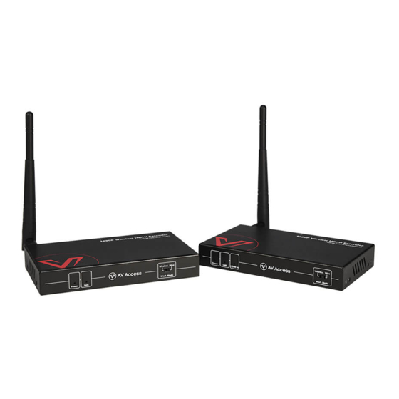
AV Access HDW100 Quick Start Manual
Hide thumbs
Also See for HDW100:
- User manual (15 pages) ,
- Quick start manual (2 pages) ,
- User manual (7 pages)
Advertisement
Quick Links
1. Application
(1) 1-1 Wireless Transmission
DVD Player
DVD Player Remote
IR Emitter
IR Receiver
Transmitter
Receiver
TV
TV
Fig 1
Note:
"Work Mode"
Fig 1
Fig 2
Switch Settings
Transmitter
Wireless
Wire
Receiver
Wireless
Wire
2. Specifications
Technical
Input A/V Port
Transmitter: 1 x HDMI
Receiver: 1 x LAN, 1 x WLAN
Input Resolutions
Up to 1080P@60Hz
Output A/V Port
Transmitter: 1 x HDMI, 1 x LAN, 1 x WLAN
Receiver: 1 x HDMI
Output Resolutions
Up to 1080P@60Hz
Compliance
HDMI 1.3, HDCP 1.4
Transmission Distance Wireless: 200m/656ft (line of sight)
Wired: 120m/394ft
General
Operating Temperature +32°F ~ +113°F (0°C ~ +45°C)
10% ~ 90%, non-condensing
Storage Temperature
-4°F ~ 140°F (-20°C ~ +70°C)
10% ~ 90%, non-condensing
Power Supply
DC 5V 1A
Power Consumption
TX: 3.5W (Max) RX: 1.6W (Max)
www.avaccess.com
(2) 1-1 Wired Transmission
DVD Player
DVD Player Remote
IR Emitter
IR Receiver
Transmitter
Receiver
TV
TV
Fig 2
info@avaccess.com
General
ESD Protection
Human body model:
• ±8kV (air-gap discharge)
• ±4kV (contact discharge)
Product Dimension
140mm x 21mm x 80mm/5.5'' x 0.83'' x 3.15"
(W x H x D)
each for TX and RX (Antennas not included)
Net Weight
TX: 0.31kg; RX: 0.30kg
Gross Weight
1.10kg
3. Package Contents
1 x Transmitter; 1 x Receiver; Others: 2 x Antennas; 2 x Power
Adapters (DC 5V 1A); 2 x Exchangeable US Plugs; 1 x IR Emitter; 1 x
IR Receiver; 4 x Mounting Ears (with Screws); 1 x Quick Start Guide
4. FAQs
(1) What should I do when Link LED is on, but there's no video output
on the remote display?
•
Check and ensure the Work Mode switches on both transmitter
and receiver(s) are set to the same positions (both at "Wireless"
or "Wire").
•
Check and ensure the HDMI source is powered on, and the
transmitter's HDMI In LED is on.
•
Connect the HDMI source device directly to the display to see if
there's signal output.
(2) How to deal with poor video quality?
•
Check if the HDMI cables are connected properly. Use different
HDMI cables if necessary.
•
Change the angles of the antennas on transmitter and receiver
to make the antennas parallel to each other (refer to Fig a).
Operation in Fig b&c is not recommended.
Transmitter
Transmitter
Receiver
Fig (a)
www.avaccess.com
Receiver
Transmitter
Receiver
Fig (b)
Fig (c)
info@avaccess.com
Advertisement

Subscribe to Our Youtube Channel
Summary of Contents for AV Access HDW100
- Page 1 1. Application General ESD Protection Human body model: (1) 1-1 Wireless Transmission (2) 1-1 Wired Transmission • ±8kV (air-gap discharge) • ±4kV (contact discharge) DVD Player DVD Player DVD Player Remote DVD Player Remote Product Dimension 140mm x 21mm x 80mm/5.5'' x 0.83'' x 3.15" (W x H x D) each for TX and RX (Antennas not included) IR Emitter...
- Page 2 • Decrease the distance between the transmitter and receiver to ensure it is within the available transmission range. • Remove other wireless signals and move any obstacles that are blocking the signal line-of-sight. (3) Why the IR remote controller seems not sensitive enough? Avoid to press and hold the IR remote controller's buttons.


Need help?
Do you have a question about the HDW100 and is the answer not in the manual?
Questions and answers