
Related Manuals for OSS EB16-Basic


Summary of Contents for OSS EB16-Basic
- Page 1 ExpressBox 16 - Basic 16-Slot Gen 2 PCI Express Expansion System EB16-Basic User’s Manual SKU: EB16-BX4 / EB16-BX8 www.onestopsystems.com...
-
Page 2: Table Of Contents
One Stop Systems Table of Contents Preface Advisories Safety Instructions Introduction General Specifications Basic Features Specifications Basic Main Components Pre-Installation Parts List Tools Required for Installation Hardware Installation Guidelines for Installation Open Enclosure Remove Card Holder Assembly Install PCIe Cards Install Host Card 2.5.1 x8 Interface Card... - Page 3 One Stop Systems PCIe slot Power Redundant Power Supply Option Interface Cards 4.3.1 x16 Interface Card LEDs 4.3.2 x16 Card Bandwidth / Lane Settings 4.3.3 x8 Interface Card LEDs and Lane Settings Backplane Backplane Block Diagram Backplane FAQs Backplane Dipswitches Backplane Power Supply Connectors 4.8.1 Backplane Aux Power Connectors...
- Page 4 One Stop Systems Industry Canada ISO 9001:2008 RoHS WEEE ExpressBox 16 Basic| 4...
-
Page 5: Preface
Used to indicate and prevent the following step from causing serious injury or significant data loss COMPATIBILITY ISSUE Used to indicate a known or potential compatibility issue between OSS and non-OSS hardware that may cause malfunction. ExpressBox 16 Basic| 5... - Page 6 One Stop Systems Disclaimer: We have attempted to identify most situations that may pose a danger, warning, or caution condition in this manual. However, OSS does not claim to have covered all situations that might require the use of a Caution, Warning, or Danger indicator.
-
Page 7: Safety Instructions
Safety Instructions Always use caution when servicing any electrical component. Before handling the OSS Expansion chassis, read the following instructions and safety guidelines to prevent damage to the product and to ensure your own personal safety. Refer to the “Advisories” section for advisory conventions used in this manual, including the distinction between Danger, Warning, Caution, Important, and Note. - Page 8 Static electricity can harm system boards. Perform service at an ESD workstation and follow proper ESD procedures to reduce the risk of damage to components. OSS strongly encourages you to follow proper ESD procedures, which can include wrist straps and smocks, when servicing equipment.
-
Page 9: Introduction
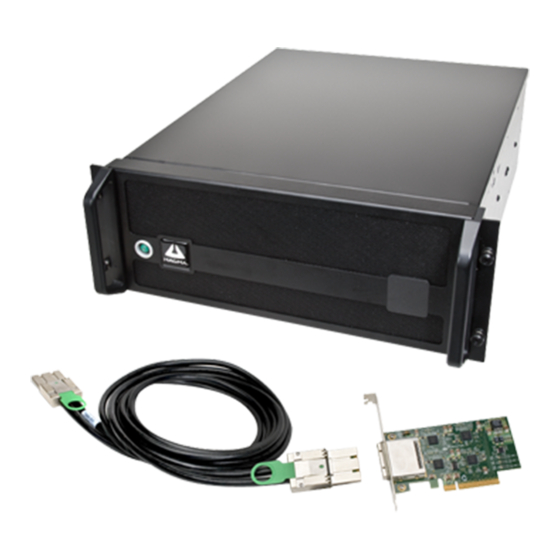
General Specifications OSS ExpressBox 16 Basic is a 16-Slot PCI Express® Expansion System. The expansion system consists of a PCIe® host interface card, an iPass cable, a 4U rack-mount chassis containing a 16 Slot backplane and an expansion interface card, a standard or redundant power supply, and high volume cooling fans. -
Page 10: Specifications
One Stop Systems Specifications Item Description Technology PCI Express Bus Specification Revision 2.0 PCI Local Bus Specification Revision 2.3 PCI Bridge Architecture Revision 1.2 Backplane EB16-BX4 - 16 slots x4 PCIe EB16-BX8 - 14 slots x8 PCIe and 2 slots x16 PCIe Interface Cards Low Profile PCIe x8 Gen 2... -
Page 11: Basic Main Components
One Stop Systems Basic Main Components ExpressBox 16 Basic| 11... -
Page 12: Pre-Installation
One Stop Systems Pre-Installation Before using the OSS Expansion chassis, you should perform the following steps: • Inventory the shipping carton contents for all of the required parts • Gather all of the necessary tools required for installation • Read this manual... - Page 13 One Stop Systems ExpressBox 16 Basic| 13...
-
Page 14: Tools Required For Installation
One Stop Systems Tools Required for Installation To complete the installation of the OSS product you will need a Phillips-head screwdriver and ESD wrist strap to prevent electrostatic discharge. ExpressBox 16 Basic| 14... -
Page 15: Hardware Installation
One Stop Systems Hardware Installation Guidelines for Installation The following steps will guide you through the installation of your OSS Expansion System. CAUTION Hardware installation shall be performed only by qualified service personnel per UL and IEC 60950-1. Electrostatic Discharge (ESD) Warning All add-in cards are susceptible to electrostatic discharge. -
Page 16: Open Enclosure
One Stop Systems Open Enclosure Loosen the 2 thumbscrews that retain the top cover of the chassis and slide the lid towards you as shown below: Remove Card Holder Assembly Remove the screw on the side of the cardholder assembly and lift upwards. Install PCIe Cards Electrostatic Discharge (ESD) Warning All add-in cards are susceptible to electrostatic discharge. - Page 17 One Stop Systems CAUTION Before touching anything inside the enclosure, move to an ESD station and follow proper ESD procedures. Failure to do so may result in electrostatic discharge, damaging the computer or its components. For more information, see “Protecting Against Electrostatic Discharge”...
- Page 18 One Stop Systems In model EB16-BX4 all sixteen slots are x4 PCIe Gen 2 as shown this diagram: PCIe PCIe Switch Switch For Model EB16-BX8 and EB16-SX8, a mixture of x8 and x16 PCIe Gen 2 slots are available as shown in this diagram. PCIe PCIe Switch...
-
Page 19: Install Host Card
Make sure that all cards are fully seated in their connectors. When correctly seated in its connector, you will notice a firm resistance when you pull up gently on the card. To keep the cards in place, secure them in the enclosure with their retaining screws (supplied with the OSS Expansion chassis. -
Page 20: X8 Interface Card
One Stop Systems When the host computer is off and all power cords are disconnected from the AC outlet, remove the cover and prepare your host card for insertion into a PCIe slot. There two types of host interface cards to use. You can use the x8 or x16. See photos below. 2.5.1 x8 Interface Card 2.5.2... -
Page 21: Which Slot To Plug In The Host Card
It is important to know how many lanes the host computer slot can support. The host card needs to be configured for the same number of lanes as the host computer slot. For example, the computer slot is set to x8 lanes; therefore, you must configure the OSS host card to x8 lanes. -
Page 22: Host Mode Dipswitch Setting
When the OSS interface card is used as “Host” interface i.e. installed in the host computer, the RED switch should remain OFF. Move the dipswitch to the ON position only if the same card is used as an “Expansion Interface” in the OSS expansion backplane. The x8 and x16 PCIe interface cards have the dipswitch to change between different modes (host and expansion). -
Page 23: Expansion Mode Dipswitch Setting
Expansion mode Dipswitch Setting The OSS “host” interface is the same card as the “expansion” interface only that its SW1 or SW2 switch is set to “ON=EXP.” By default, the expansion interface card should already be installed in the Expansion chassis. -
Page 24: Connect Cables
Depending on the interface cards, a x16 PCIe or x8 PCIe 3-meter iPass cable is included. Carefully position the expansion chassis so that the expansion cable will conveniently reach from the host computer to the OSS Expansion chassis. Cables attached to the expansion chassis must be securely fastened. When you hear a “click,” it is properly secured. If not securely connected, the connectors may cause intermittent or lost connections. -
Page 25: Connect Power Cables
One Stop Systems NOTE If possible, plug all power cords from the expansion chassis and your host computer into a shared power strip, preferably one that has surge and noise suppression circuitry built into it. Connect Power Cables Connect the power cable to the power receptacle of the power supply located on the back of the unit. For EB16 Smart, you need two power cables and one power cable for EB16 Basic. - Page 26 One Stop Systems Check your installation before powering up the OSS Expansion chassis for the first time. Although the power supply has an over voltage protection device built into it, it may not "trip" in time to fully protect a device that has been improperly connected, or whose power cable has been damaged.
-
Page 27: Power On Computer
To effectively use your OSS chassis as part of your computer system, ensure that all the proper connections are made. Then power on your computer. This will enable your OSS chassis to turn ON. The OSS chassis can also turn ON by itself by pressing the main switch on the front panel and then turning on the computer. -
Page 28: Software - Verify Installation
Windows No additional software or drivers are needed. The operating system should automatically recognize the OSS expansion chassis. To verify a successful installation on Windows, find the ‘My Computer’ icon and “right-click” on it. Then select ‘Manage’ from the pop-up menu. - Page 29 The Device Manager will display the available slots within the chassis. As reference, you can determine which slot you inserted your PCIe card in by following the outline that is shown below. The OSS chassis has 2 PCIe Switch devices that enable the slots to work: ...
-
Page 30: Mac Os
The following screen may be displayed the first time you turn on your computer with the OSS Expansion chassis installed. Mac OS X is prompting you to choose a PCI Express profile that maximizes the performance of your attached devices. The OSS host interface card can communicate up to a bandwidth of x16, x8, or x4 from and to the expansion chassis and devices. -
Page 31: Linux
If any of these devices are not displayed as shown above, you should shut down your system (computer first, then the expansion chassis) and reconnect the cables and the host interface card to ensure that you have a solid connection. Then restart the OSS Expansion chassis followed by the computer. -
Page 32: System Should Be Up And Running
We will provide reasonable technical support with 3rd Party cards. However, if you have verified a successful installation of the OSS Expansion chassis, but experience difficulty installing your 3rd Party cards, the card manufacturer should be able to provide the best support. -
Page 33: Other Technical Information
One Stop Systems Other Technical Information PCIe slot Power Be AWARE of the power consumption of any 3rd party card that is inserted into the slot of the device. Each individual slot is capable of outputting 75 Watts of power. If at any time the cards inserted exceed the maximum amount of power that is available from every slot, then one power supply would not suffice. -
Page 34: Redundant Power Supply Option
One Stop Systems Redundant Power Supply Option The Power Supply units that are used within this chassis are shared by the electrical components within the chassis. Both units effectively distribute power until one unit becomes nonoperational. In this case, the effect of power distribution is shifted to the functional Power Supply. Further information about the Power supply’s electromagnetic capability (EMC) is listed below: DANGER or STOP DO NOT TEMPER WITH THE INTERIOR POWER CONNECTIONS THAT LINKS TO CONNECTORS J24 AND J25. -
Page 35: Interface Cards
CONNECTORS J20, J21, J22, and J23 within the chassis will provide additional power to any PCI Express Card that requires it. The outputs from these connectors are 12V @ 10A each. Users should purchase a OSS cable P/N# 01-05996-03 for this capability. -
Page 36: X16 Card Bandwidth / Lane Settings
Card Bandwidth / Lane Settings The width of the active data lanes may vary based on the PCIe slot that you are using for your OSS host interface card. Be sure to check the PCIe slot in your computer to determine how many data lanes it can support. It should be labeled near the slot. The default value that the card is operating in is x16. -
Page 37: X8 Interface Card Leds And Lane Settings
One Stop Systems 4.3.3 x8 Interface Card LEDs and Lane Settings The card that is x8-capable (uses x8 iPass cable) contains status indicators that tell users the condition it is currently operating in. There are LED indicators for the lanes that are being used for data transfer and whether the board is powered correctly. A switch is also available to change the amount of lanes that would be operational for usage by the user. -
Page 38: Backplane
One Stop Systems Backplane This is current (new) EB16 backplane. ExpressBox 16 Basic| 38... -
Page 39: Backplane Block Diagram
One Stop Systems There are 17 slots in the EB16 unit, from slot 0 to slot 16. Slot0 is the designated slot for expansion interface card. There are three x16 PCIe slots and thirteen x8 PCIe slots. Main board (with 16 slot PCIe slots) is Gen 2 with PLX PCIe switch. ... -
Page 40: Backplane Faqs
One Stop Systems Backplane FAQs Question#1 How many lanes are available on EB16? Answer: There are 192 Lanes Available Question#2 There are two switches on the EB16. How many lanes are in-between these two or lanes allocated per switch? Answer: Total allocated 96 lanes on first Switch station 1 (From slot1 to slot6) ... -
Page 41: Backplane Dipswitches
One Stop Systems Backplane Dipswitches The following dipswitches on the EB16 board are for internal manufacturing use only for programming EEPROM. SW2, SW4, SW5 , SW7, SW9, SW10, SW11 DO NOT TOUCH THIS!!! DO NOT CHANGE SETTINGS!! Changing or moving the dipswitches will corrupt the EEPROM, which will render the slots or the entire expansion board non-operational. - Page 42 One Stop Systems ExpressBox 16 Basic| 42...
-
Page 43: Backplane Power Supply Connectors
One Stop Systems Backplane Power Supply Connectors The pictures below are the two female Power Supply connectors (18-pin connector) on the main board / backplane. 4.8.1 Backplane Aux Power Connectors These are the four Auxiliary power connectors available on the main board / backplane. It is a10-pin power connector. 4.8.2 Fan Connectors &... -
Page 44: Auxiliary Power Cables
There are two types of auxiliary power cables available for the EB16 units (Smart and Basic models), the 6/8-pin aux cable (SKU#: 01-05996-04) and the 4-/6-pin aux cable (SKU#: 01-05996-03) . The cables are sold separately, you need to contact OSS Sales to order the item. - Page 45 One Stop Systems ExpressBox 16 Basic| 45...
-
Page 46: Backplane Leds
One Stop Systems 4.10 Backplane LEDs 4.10.1 Power Management Backplane This backplane system controls the power distribution to the entire PCIe device. Ensure that this device is working properly by indicating that the LEDs are ON. It is attached to the side panel within the chassis near the power supply module. 4.10.2 Backplane Power Indicator Other than the indicators on the front panel, the backplane board that is located within the chassis contains LEDs that provide status of the... - Page 47 One Stop Systems Other indicators that are located on the backplane are the LEDs that identify the type of card that is inserted into a slot. This is in regards to the number of lanes and speed that the card possesses. As shown below, the LEDs are located at the bottom of each individual slot. When will the lit LED remain consistent is dependent on whether the inserted card is using the maximum capability of the backplane’s PCIe slot.
-
Page 48: Chassis Maintenance
Chassis Cleaning The environment where your OSS chassis is operating should be the determining factor as to how often you should perform a general cleanup of the chassis. To perform a routine general cleaning of your chassis, you will need the following:... - Page 49 IMPORTANT If your chassis is extremely dirty and you would like professional help with getting it clean, you can contact OSS Support for instructions and costs on shipping the chassis back for cleaning. Finally, clean the air filter following the instructions later in this chapter. When finished, replace the cover and turn on power to the system.
-
Page 50: Fan Replacement
Then locate the fan that has failed, unlock its thumbscrew, lift up its metal tab and pull it out. Insert the new fan in and secure it in place. Verify the new fan is spinning and restore the chassis lid. NOTE The OSS part number for a replacement fan is: 26-00031-00 ExpressBox 16 Basic| 50... -
Page 51: Power Supply Replacement
In spite of regular performance of routine maintenance tasks, some computer systems can experience hardware failures. Fortunately, your investment in a OSS Expansion chassis with a redundant power supply provides you with the ability to easily replace a power module in the event of a failure. - Page 52 In order to ensure the safety and efficiency of your expansion chassis, it is recommended that you keep a spare power supply module on hand – just in case. Protect yourself, keep a spare. Order your spare power supply module from OSS – PN # 40-00031-00. ExpressBox 16 Basic| 52...
-
Page 53: Troubleshooting
Locate the Problem If you are having trouble with the OSS Expansion chassis, first verify that all cards and cables are seated properly. Be sure you followed the instructions in earlier sections of this manual. Always remember to power On and Off correctly when rechecking your installation. If you are still having problems, try these troubleshooting steps: The OSS expansion chassis is correctly displayed as a “PCI standard PCI-to-PCI bridge”... -
Page 54: Computer Doesn't Detect The Expansion System
Also verify the OSS host interface card is properly inserted into the host computer slot. In case any other LED is off, ensure the respective card is functional and properly seated in its slot. -
Page 55: Add-In Pcie Card Not Recognized
Party card or the card drivers. You should go to the Windows Error Codes section of this chapter to learn how to troubleshoot using error codes. If the is still visible, the problem may be with the OSS Expansion chassis. Contact OSS Technical Support for further guidance and/or a replacement product. MacOS Open the Apple System Profiler and the 3 Party card(s) should now be visible. -
Page 56: Support For 3 Rd Party Pcie Cards
Party PCIe cards OSS will provide reasonable technical support to with 3rd Party cards. However, if you have verified a successful installation of the OSS Expansion chassis but experience difficulty installing your 3rd Party cards, the card manufacturer should be able to provide the best support. -
Page 57: Computer Hangs After Many Card Installed
(be it located on the host system or on OSS’s expansions chassis) is allocated Input/Output memory space for proper operation. By installing multiple add-in cards in one chassis or chaining multiple OSS chasses (as discussed in: Appendix A), we are requesting more and more resources from the BIOS and thus must make sure we pre-allocate them sufficiently. -
Page 58: How To Get More Help
One Stop Systems How to Get More Help You can visit the Technical Support FAQ pages on the Internet at https://www.onestopsystems.com/support Contacting Technical Support Our support department can be reached by phone at 1 (760) 745-9883. Support is available Monday through Friday, 8:00 AM to 5:00 PM PT. When contacting Technical Support make sure to include the following information: 1. -
Page 59: Appendix A Compliance
This Class A digital apparatus complies with Canadian ICES-003. Cetappareilnumériqué de la classe A estconformé à la norme NMB-003 du Canada The product(s) described in this manual complies with all applicable European Union (CE) directives. OSS will not retest or recertify systems or components that have been reconfigured by customers... - Page 60 One Stop Systems Manual P/N 09-09979-00 Rev C ExpressBox 16 Basic| 60...
Need help?
Do you have a question about the EB16-Basic and is the answer not in the manual?
Questions and answers