Table of Contents
Advertisement
Quick Links
Advertisement
Table of Contents

Related Manuals for LifeGear 77004


Summary of Contents for LifeGear 77004
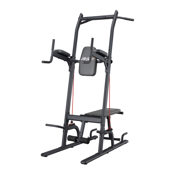
- Page 1 POWER TOWER ITEM NO: 77004 OWNER’S MANUAL IMPORTANT: Read all instructions carefully before using this product. Retain this owner’s manual for future reference. The specifications of this product may vary from this photo and are subject to change without prior notice.
-
Page 2: Table Of Contents
TABLE OF CONTENTS WARRANTY ------------------------------------------------------------------------------- 2 IMPORTANT SAFETY INSTRUCTIONS ------------------------------------------- 3 PARTS LIST ------------------------------------------------------------------------------- 4 HARDWARE KIT 1 ----------------------------------------------------------------------- 5 HARDWARE KIT 2 ----------------------------------------------------------------------- 6 EXPLODED VIEW ----------------------------------------------------------------------- 7 ASSEMBLY INSTRUCTIONS --------------------------------------------------------- 8 MAINTENANCE -------------------------------------------------------------------------- 17 ADJUSTMENTS -------------------------------------------------------------------------- 17 WARM UP AND COOL DOWN ROUTINE ----------------------------------------- 22... -
Page 3: Warranty
ONE YEAR LIMITED WARRANTY LifeGear Inc. warrants to the original purchaser that this product is free from defects in material and workmanship when used for the purpose intended, under the conditions that it has been installed and operated in accordance with LifeGear's Owner's Manual. LifeGear's obligation under this warranty is limited to replacing or repairing free of charge, any parts which may prove to be defective under normal home use. -
Page 4: Important Safety Instructions
IMPORTANT SAFETY INSTRUCTIONS Basic precautions should always be followed, including the following important safety instructions when using this Power Tower. Read all instructions before using this Power Tower. Read all the instructions in this manual and do warm up exercises before using the Power Tower. -
Page 5: Parts List
PARTS LIST Description Qty No. Description 001 Base Tube 2 025 Hexagon Head Bolt (M10x100) 002 Upright Tube 2 026 Curve Washer (Ø10xØ20x2.0T) 003 Upright Tube Support 2 027 Hexagon Head Bolt (M10x60) 004 Right Handle 1 028 Hexagon Head Bolt (M8x85) 005 Left Handle 1 029 Curve Washer Ø8 006 Bottom Cross Bar... -
Page 6: Hardware Kit 1
HARDWARE KIT 1 STEP 1 Part# 24 (M10; 12 pcs) Part# 22 (M10x55; 8 pcs) Part# 23 (Ø10; 8 pcs) Part# 25 (M10x100; 4 pcs) Part# 26 (Ø10; 8 pcs) STEP 2 STEP 4 STEP 5 Part# 24 (M10; 4 pcs) Part# 24 (M10;... -
Page 7: Hardware Kit
HARDWARE KIT 2... -
Page 8: Exploded View
EXPLODED VIEW... -
Page 9: Assembly Instructions
ASSEMBLY INSTRUCTIONS NOTE: We recommend that two people be available for assembly of this Power Tower. Hardware: 17 mm Part# 22 (M10x55; 4 pcs) Part# 23 (Ø10; 4 pcs) Part# 24 (M10; 4 pcs) STEP 1-1 Attach the Upright Tube (2) onto the Base Tube (1) with two Carriage Bolts (22), two Washers (23), and two Nylon Nuts (24). - Page 10 Hardware: 17 mm Part# 22 (M10x55; 4 pcs) Part# 23 (Ø10; 4 pcs) Part# 24 (M10; 4 pcs) STEP 1-2 Attach the Upright Tube Support (3) onto the Base Tube (1) with two Carriage Bolts (22), two Washers (23), and two Nylon Nuts (24). Tighten nylon nuts with the Double Open End Wrench provided.
- Page 11 Hardware: 17 mm 17 mm Part# 24 (M10; 4 pcs) Part# 27 (M10x60; 4 pcs) Part# 23 (Ø10; 8 pcs) STEP 2 Attach both Upright Tubes (2) to both sides of the Bottom Cross Bar (6) with four Nylon Nuts (24), four Hexagon Head Bolts (27), and eight Washers (23).
- Page 12 Hardware: 17 mm 17 mm Part# 23 (Ø10; 8 pcs) Part# 24 (M10; 4 pcs) Part# 31 (M10x45; 4 pcs) STEP 4 Attach the Top Cross Bar (8) onto both Dip Arms (7) with four Nylon Nuts (24), four Hexagon Head Bolts (31), and eight Washers (23).
- Page 13 17 mm Hardware: 17 mm Part# 23 (Ø10; 8 pcs) Part# 24 (M10; 4 pcs) Part# 32 (M10x50; 4 pcs) STEP 5-2 Attach the Pull-Up Bar (9) onto both Adjustable Upper Upright Tubes (11) with two Support Plates (10), four Nylon Nuts (24), four Hexagon Head Bolts (32), and eight Washers (23). Tighten bolts and nylon nuts with two Double Open End Wrenches provided.
- Page 14 14 mm Hardware: Part# 33 (Ø8; 2 pcs) Part# 34 (M8x15; 2 pcs) STEP 6-1 Attach the Backrest (12) onto the Top Cross Bar (8) with two Hexagon Head Bolts (34) and two Washers (33). Tighten bolts with the Double Open End Wrench provided. Hardware: Part# 28 (M8x85;...
- Page 15 STEP 6-3 Clip the snap hook of the Resistance Band (14) onto loop at the Upright Tube (2) or Base Tube (1). Repeat on other side.
- Page 16 Hardware: Part# 24 (M10; 2 pcs) Part# 26 (Ø10; 2 pcs) Part# 45 (M10x95; 2 pcs) 17 mm STEP 7-1 Attach the Ankle Support Tube (37) onto the Bottom Cross Bar (6) with two Carriage Bolts (45), two Curve Washers (26), and two Nylon Nuts (24). Tighten nylon nuts with the Double Open End Wrench provided.
- Page 17 Hardware: 17 mm 17 mm Part# 23 (Ø10; 2 pcs) Part# 24 (M10; 1 pc) Part# 27 (M10x60; 1 pc) Part# 42 (1 pc) STEP 7-3 Slide the Bench Frame (35) into the Bottom Cross Bar (6) and align one hole on the Bench Frame (35) with one hole on the Bottom Cross Bar (6).
-
Page 18: Maintenance
MAINTENANCE The Power Tower can be cleaned with a soft cloth. Please wipe your perspiration off the Power Tower after each use. Please inspect all assembly bolts and nylon nuts on the Power Tower for proper tightness every week. Replace missing nylon nuts and bolts. Securely tighten loose nylon nuts and bolts. - Page 19 Pull-Up Bar Upright Tube Lock Knob Adjusting the Pull-Up Bar Height Remove both Lock Knobs by turning them counterclockwise direction. Slide both Upright Tubes up or down direction to the desired position. Lock both Upright Tubes in place by turning Lock Knobs in a clockwise direction. NOTE: Make sure that the Lock Knobs are locked in place before using the pull-up bar.
- Page 20 Weight Bench Backrest Can Be Adjusted to Decline and Flat Positions. Adjusting the Weight Bench Backrest to Flat Position 1 A. Pull out the Pin (42) from the top adjustment holes in the Bottom Cross Bar (6). B. Lift the Bench Frame (35) and lock it in position by inserting the Pin (42) through the bottom adjustment holes in the Bottom Cross Bar (6) and the holes in the Bench Frame (35).
- Page 21 Adjusting the Weight Bench Backrest to Flat Position 3 Fold down the Bench Support Tube (36) and then lock the Bench Support Tube (36) in position by inserting the Pin (42) through the bottom adjustment holes in the Bench Frame (35) and the holes in the Bench Support Tube (36).
- Page 22 Folding Up the Weight Bench to Storage Position A. Pull out the Pin (42) from the top adjustment holes in the Bottom Cross Bar (6). B. Fold up the weight bench and lock in position by inserting the Pin (42) through the top adjustment holes in the Bottom Cross Bar (6) and the holes in the Bench Frame (35).
-
Page 23: Warm Up And Cool Down Routine
WARM UP AND COOL DOWN ROUTINE The WARM-UP is an important part of any workout. The purpose of warming up is to prepare your body for exercise and to minimize injuries. Warm up for two to five minutes before aerobic exercising. It should begin every session to prepare your body for more strenuous exercise by heating up and stretching your muscles, increasing your circulation and pulse rate, and delivering more oxygen to your muscles. - Page 24 QUADRICEPS STRETCH With one hand against a wall for balance, reach behind you and pull your right foot up. Bring your heel as close to your buttocks as possible. Hold for 15 counts and repeat with left foot. INNER THIGH STRETCH Sit with the soles of your feet together and your knees pointing outward.
Need help?
Do you have a question about the 77004 and is the answer not in the manual?
Questions and answers