Sungrow SG5KTL-MT User Manual
Pv grid-connected inverter
Hide thumbs
Also See for SG5KTL-MT:
- User manual (112 pages) ,
- Quick manual (16 pages) ,
- Quick manual (16 pages)
Table of Contents
Advertisement
Quick Links
S S G G 5 5 _ _ 6 6 K K T T L L - - M M T T & & S S G G 8 8 _ _ 1 1 0 0 _ _ 1 1 2 2 K K T T L L - -
M M P P V V G G r r i i d d - - c c o o n n n n e e c c t t e e d d I I n n v v e e r r t t e e r r U U s s e e r r
M M a a n n u u a a l l S S G G 5 5 – – 1 1 2 2 K K ( ( W W W W ) ) - - U U E E N N - -
V V e e r r 1 1 5 5 – – 2 2 0 0 2 2 0 0 0 0 4 4 V V e e r r s s i i o o n n : : 1 1 . . 5 5
SG5–12K(WW)-UEN-Ver15–202004 Version:1.5
SG5_6KTL-MT&SG8_10_12KTL-M
P P V V G G r r i i d d - - c c o o n n n n e e c c t t e e d d I I n n v v e e r r t t e e r r
U U s s e e r r M M a a n n u u a a l l
Advertisement
Table of Contents

Related Manuals for Sungrow SG5KTL-MT


Summary of Contents for Sungrow SG5KTL-MT
- Page 1 S S G G 5 5 _ _ 6 6 K K T T L L - - M M T T & & S S G G 8 8 _ _ 1 1 0 0 _ _ 1 1 2 2 K K T T L L - - M M P P V V G G r r i i d d - - c c o o n n n n e e c c t t e e d d I I n n v v e e r r t t e e r r U U s s e e r r M M a a n n u u a a l l S S G G 5 5 –...
-
Page 3: All Rights Reserved
It is prohibited to use data contained in firmware or software developed by • SUNGROW, in part or in full, for commercial purposes by any means. It is prohibited to perform reverse engineering, cracking, or any other operations that •... -
Page 4: About This Manual
. . s s u u n n g g r r o o w w p p o o w w e e r r . . c c o o m m or on the webpage of the respective component manufacturer. V V a a l l i i d d i i t t y y This manual is valid for the following inverter models: SG5KTL-MT • SG6KTL-MT • SG8KTL-M •... - Page 5 S S y y m m b b o o l l E E x x p p l l a a n n a a t t i i o o n n Indicates a situation that, if not avoided, could result in equipment or property damage.
-
Page 7: Table Of Contents
C C o o n n t t e e n n t t s s All Rights Reserved .....................I About This Manual .....................II 1 Safety ......................1 1.1 PV Panels..................... 1 1.2 Utility Grid ....................1 1.3 Inverter ......................2 1.4 Skills of Qualified Personnel................ - Page 8 4.5 Installing the Inverter .................. 19 4.6 Connecting the Communication Module (Optional) ........20 5 Electrical Connection ................21 5.1 Safety Instructions..................21 5.2 Terminal Description................... 21 5.3 Additional Grounding Connection ............... 22 5.3.1 Additional Grounding Requirements..........22 5.3.2 Connection Procedure ..............23 5.4 AC Cable Connection .................
- Page 9 7.7.1 Operation Parameters............... 44 7.7.2 Protection Parameter................ 48 7.7.3 Firmware Update................49 7.7.4 Feed-in Limitation (Optional)............. 50 8 System Decommissioning ..............52 8.1 Disconnecting the Inverter................52 8.2 Dismantling the Inverter................53 8.3 Disposal of the Inverter................53 9 Troubleshooting and Maintenance ............
-
Page 11: Safety
The safety instructions in this manual cannot cover all the precautions that • should be followed. Perform operations considering actual onsite conditions. SUNGROW shall not be held liable for any damage caused by violation of • the safety instructions in this manual. 1.1 PV Panels PV strings will produce electrical power when exposed to sunlight and can cause a lethal voltage and an electric shock. -
Page 12: Inverter
1 Safety User Manual All electrical connections must be in accordance with local and national standards. Only with the permission of the utility grid, the inverter can be connected to the utility grid. 1.3 Inverter Danger to life from electric shocks due to live voltage. Do not open the enclosure at any time. -
Page 13: Skills Of Qualified Personnel
User Manual 1 Safety Only qualified personnel can perform the country setting. Unauthorized alteration of the country setting may cause a breach of the • type-certificate marking. Risk of inverter damage due to electrostatic discharge (ESD). • By touching the electronic components, you may damage the inverter. For inverter handling, be sure to: avoid any unnecessary touching;and, •... -
Page 14: Product Description
Product Description 2.1 Intended Use SG5KTL-MT/SG6KTL-MT/SG8KTL-M/SG10KTL-M/SG12KTL-M; a transformerless 3- phase PV grid-connected inverter, is an integral component in the PV power system. The inverter is designed to convert the direct current power generated from the PV modules into grid-compatible AC current and feeds the AC current to the utility grid. The intended usage of the inverter is illustrated in "figure 2-1 Inverter application in PV power... -
Page 15: Product Introduction
2 Product Description 2.2 Product Introduction 2.2.1 Model Description The model description is as follows (Take SG5KTL-MT as an example): table 2-1 Power level description M M o o d d e e l l N N o o m m i i n n a a l l O O u u t t p p u u t t P P o o w w e e r r... -
Page 16: Appearance
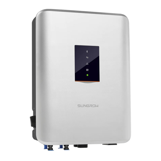
2 Product Description User Manual 2.2.2 Appearance f f i i g g u u r r e e 2 2 - - 2 2 Appearance * The image shown here is for reference only. The actual product you receive may differ. D D e e s s c c r r i i p p t t i i o o n n N N o o . -
Page 17: Dimensions
User Manual 2 Product Description 2.2.3 Dimensions f f i i g g u u r r e e 2 2 - - 3 3 Dimensions of the inverter(in mm) 2.2.4 LED Indicator Panel As an HMIe, the LED indicator panel on the front of the inverter can indicate the present working state of the inverter. -
Page 18: Dc Switch
2 Product Description User Manual L L E E D D i i n n d d i i c c a a t t o o r r L L E E D D c c o o l l o o r r L L E E D D s s t t a a t t e e D D e e f f i i n n i i t t i i o o n n No device is connected to the inverter... -
Page 19: Circuit Diagram
User Manual 2 Product Description The inverter operates automatically when input and output requirements are met. Rotate the DC switch to the “OFF” position to stop the inverter when a fault occurs or when you need to stop the inverter. Turn the DC switch to the “ON”... - Page 20 The communication accessory port is used to connect communication module • manufactured by SUNGROW, and upload monitoring data by means of wireless communication. The inverter can be connected to communication devices via either of the two interfaces. After communication connection is established, users can view inverter information or set inverter parameters through the iSolarCloud.
- Page 21 User Manual 2 Product Description Before enabling the PID recovery function, make sure the voltage polarity of • the PV modules to ground meets requirement. If there are any questions, contact the PV module manufacturer or read its corresponding user manual. If the voltage scheme for the PID recovery function does not meet the •...
-
Page 22: Unpacking And Storage
Check the inner contents for damage after unpacking. • Contact SUNGROW or the supplier in case there is any damage or incompleteness. Do not dispose of the original packing case. It is recommended to store the inverter in it. 3.2 Identifying the Inverter The nameplate can be found on both the inverter and the packing case. -
Page 23: Scope Of Delivery
I I t t e e m m D D e e s s c c r r i i p p t t i i o o n n SUNGROW logo and product model Technical data of inverter Instructions and marks of conformity... -
Page 24: Inverter Storage
3 Unpacking and Storage User Manual Q Q u u a a n n t t i i t t y y D D e e s s c c r r i i p p t t i i o o n n I I t t e e m m N N a a m m e e Inverter... -
Page 25: Mechanical Mounting
Mechanical Mounting 4.1 Safety during Mounting Make sure there is no electrical connection before installation. In order to avoid electric shock or other injury, be sure there is no electricity or plumbing installations before drilling holes. Risk of injury due to improper handling Always follow the instructions when moving and positioning the inverter. -
Page 26: Carrier Requirements
4 Mechanical Mounting User Manual The ambient temperature and relative humidity must meet the following • requirements. Prevent the inverter from direct exposure to sun, rain and snow. • The inverter should be well ventilated. Ensure air circulation. • Never install the inverter in living areas. The inverter will generate noise during •... -
Page 27: Installation Clearance Requirements
User Manual 4 Mechanical Mounting 4.2.4 Installation Clearance Requirements Reserve enough clearance around the inverter to ensure sufficient space for heat • dissipation. In case of multiple inverters, reserve specific clearance between the inverters. •... -
Page 28: Installation Tools
4 Mechanical Mounting User Manual Install the inverter at an appropriate height for ease of viewing LED indicators and • operating switches. 4.3 Installation Tools Installation tools include but are not limited to the following recommended ones. If necessary, use other auxiliary tools on site. table 4-1 Tool specification S S p p e e c c i i f f i i c c a a t t i i o o n n N N o o . -
Page 29: Moving The Inverter
User Manual 4 Mechanical Mounting 4.4 Moving the Inverter To install the inverter, remove the inverter from the packaging and move it to the installation site. Follow the instructions below as you move the inverter: Always be aware of the weight of the inverter. •... -
Page 30: Connecting The Communication Module (Optional)
4 Mechanical Mounting User Manual Check to ensure that there is no other electronic or plumbing installed inside the wall before drilling holes. step 4 Secure the wall-mounting bracket to the wall firmly with the supplied expansion bolt sets. step 5 Lift the inverter and slide it down along the wall-mounting bracket to make sure they match perfectly. -
Page 31: Electrical Connection
Electrical Connection 5.1 Safety Instructions Prior to any electrical connections, keep in mind that the inverter has dual power supplies. It is mandatory for the qualified personnel to wear personal protective equipment (PPE) during the electrical work. Danger to life due to a high voltage inside the inverter! The PV string will generate lethal high voltage when exposed to sunlight. -
Page 32: Additional Grounding Connection
5 Electrical Connection User Manual f f i i g g u u r r e e 5 5 - - 1 1 Terminal description * The image shown here is for reference only. The actual product you receive may differ. D D e e s s c c r r i i p p t t i i o o n n N N o o . -
Page 33: Connection Procedure
User Manual 5 Electrical Connection When there is only one inverter in the PV system, connect the additional grounding cable to a nearby grounding point. When there are multiple inverters in the PV system, connect grounding points of all inverters and the PV array frames to the equipotential cable (according to the onsite conditions) to implement an equipotential connection. -
Page 34: Ac Cable Connection
M M u u l l t t i i p p l l e e I I n n v v e e r r t t e e r r s s i i n n p p a a r r a a l l l l e e l l C C o o n n n n e e c c t t i i o o n n If multiple inverters are connected in parallel to the grid, ensure that the total number of parallel inverters does not exceed 10. Otherwise, please contact SUNGROW for technical scheme. -
Page 35: Assembling The Ac Connector
User Manual 5 Electrical Connection All the AC cables should be equipped with correctly colored cables for distinguishing. Please refer to related standards about the wiring color. 5.4.2 Assembling the AC Connector The AC terminal block is on the bottom of the inverter. AC connection is the three- phase-four-wire grid +PE connection (L1, L2, L3, N, and PE). - Page 36 5 Electrical Connection User Manual step 5 When using a multi-core multi-strand copper wire cable, connect the AC cable head to the cord end terminal by appropriate torque. Select appropriate cord end terminal according to the cable cross-section • area. In case of single-strand copper wire, skip installing any cord end terminal.
-
Page 37: Installing The Ac Connector
User Manual 5 Electrical Connection 5.4.3 Installing the AC Connector High voltage inside the inverter! Ensure all cables are voltage-free before electrical connection. Do not connect the AC circuit breaker until all inverter electrical connections are completed. step 1 Disconnect AC circuit breaker secure it against reconnection. step 2 Insert the AC connector into the input terminals on the bottom of the inverter until there is an audible sound. -
Page 38: Dc Cable Connection
5 Electrical Connection User Manual Observe the terminal layout on the block. Do not connect the phase wires to "PE" terminal or PE wire to "N" terminal. Otherwise, unrecoverable damage to the inverter may follow. step 6 Connect AC circuit breaker to utility grid. step 7 Make sure all AC cables are firmly installed. -
Page 39: Dc Side Requirements
SG12KTL-M 5.5.2 DC Side Requirements SUNGROW provides corresponding plug connectors in the scope of delivery for quick connection of PV inputs. DC cables should be connected to the inverter via PV connectors which are included in the scope of delivery. -
Page 40: Assembling The Pv Connector
• Use MC4– Evo2 DC terminals if the maximum input voltage is greater than • 1,000V. To purchase the MC4–Evo2 DC terminals, contact SUNGROW. Select appropriate DC terminals as required above. Otherwise, SUNGROW • shall be held no liability for the damage caused. -
Page 41: Installing The Pv Connector
User Manual 5 Electrical Connection For further assembly and connection instruction, please visit the website of the device manufacturer. step 4 Check for polarity correctness. The inverter will not function properly if any PV polarity is reversed. - - - - E E n n d d 5.5.4 Installing the PV Connector step 1 Rotate the DC switch to “OFF”... -
Page 42: Rs485 Communication System
Arc or contactor over-temperature may occur if the PV connectors are not • firmly in place, and SUNGROW shall not be held liable for any damage caused. step 4 Follow the foregoing steps to connect PV connectors of other PV strings. - Page 43 User Manual 5 Electrical Connection The communication accessory port can directly connect to communication modules produced by SUNGROW, such as GPRS, WiFi, or E-Net, for which, refer to the section "5.7 GPRS Communication System (Optional)" and the section "5.8 Ethernet Communication System (Optional)".
-
Page 44: Gprs Communication System (Optional)
- - - - E E n n d d 5.7 GPRS Communication System (Optional) Connect the GPRS module produced by SUNGROW to the communication accessory port. After successful connection, information such as power generation and running state of the inverter can be viewed via the App on the phone. -
Page 45: Ethernet Communication System (Optional)
5 Electrical Connection 5.8 Ethernet Communication System (Optional) Connect the WiFi or E-Net module produced by SUNGROW to the communication accessory port. After successful connection, information such as power generation and running state of the inverter can be viewed via the App on the phone. -
Page 46: On The Inverter Side
5 Electrical Connection User Manual 5.9.2 On the Inverter Side Proceed as follows to connect the RS485 communication cable to the inverter: step 1 Prepare the RJ45 plug. Specifically, refer to the related description in section "5.6 RS485 Communication System". Skip performing the foregoing step 1 when the RS485 communication cable has been prepared. -
Page 47: Commissioning
Commissioning 6.1 Inspection before Commissioning Check the following items before starting the inverter: The inverter DC switch and external circuit breaker are disconnected. • The inverter should be accessible for operation, maintenance and service. • Nothing is left on the top of the inverter. •... -
Page 48: Isolarcloud App
App. *In case of WLAN direct login, the WiFi wireless communication module researched and manufactured by SUNGROW is required. The iSolarCloud App can also establish communication connection to the inverter via the base station or Bluetooth, thereby achieving maintenance on the inverter. -
Page 49: Login
User Manual 7 iSolarCloud App 7.3 Login 7.3.1 Requirements The following items should meet requirements: The AC and DC sides or the AC side of the inverter is powered-on. • The WLAN function of the mobile phone is enabled. • The mobile phone is within the coverage of the wireless signal of the WiFi module. -
Page 50: Function Overview
7 iSolarCloud App User Manual f f i i g g u u r r e e 7 7 - - 1 1 WLAN Direct step 4 If the inverter is not initialized, you will enter the quick setting screen of initialize protection parameter. -
Page 51: Home
User Manual 7 iSolarCloud App f f i i g g u u r r e e 7 7 - - 3 3 App function tree map 7.5 Home Home page of the App is shown in the following figure. f f i i g g u u r r e e 7 7 - - 4 4 Home table 7-1 Home page description D D e e s s c c r r i i p p t t i i o o n n... -
Page 52: Chart
7 iSolarCloud App User Manual D D e e s s c c r r i i p p t t i i o o n n N N o o . . N N a a m m e e Today yield Shows today power generation of the inverter Total yield... -
Page 53: More
User Manual 7 iSolarCloud App f f i i g g u u r r e e 7 7 - - 5 5 Power curve step 2 Slide the screen left to view monthly power generation histogram, annual power generation histogram, and total power generation histogram. - - - - E E n n d d 7.7 More Tap "More"... -
Page 54: Operation Parameters
7 iSolarCloud App User Manual The "More" screen supports the following operations: Set parameters including inverter operation parameters, protection parameters, and • power regulation. Upgrade inverter firmware (ARM/DSP/PVD/CPLD). • 7.7.1 Operation Parameters A A c c t t i i v v e e & & r r e e a a c c t t i i v v e e p p o o w w e e r r p p a a r r a a m m e e t t e e r r s s table 7-3 Description of Active &... - Page 55 User Manual 7 iSolarCloud App R R e e a a c c t t i i v v e e p p o o w w e e r r r r e e g g u u l l a a t t i i o o n n The inverter provides a reactive power regulation function.
- Page 56 7 iSolarCloud App User Manual f f i i g g u u r r e e 7 7 - - 7 7 Reactive Power Regulation Curve in Q(P) Mode “ “ Q Q ( ( U U ) ) ” ” M M o o d d e e The reactive power ratio changes with the grid voltage.
- Page 57 User Manual 7 iSolarCloud App D D e e f f a a u u l l t t R R a a n n g g e e P P a a r r a a m m - - D D e e s s c c r r i i p p t t i i o o n n G G e e n n e e r r a a l l G G e e n n e e r r a a l l...
-
Page 58: Protection Parameter
Set the grid type to correct value according to definitions of power plant scenario and non-power plant scenario. Otherwise, the inverter will run abnormally or even be damaged, and SUNGROW shall not be held liable for any damage caused. Power plant scenario: The inverter is applied to a power plant whose •... -
Page 59: Firmware Update
P P r r e e p p a a r r a a t t i i o o n n o o f f f f i i r r m m w w a a r r e e u u p p g g r r a a d d e e p p a a c c k k a a g g e e Contact the supplier or SUNGROW to get the upgrade package (.sgu file) and store the package in the specified path. -
Page 60: Feed-In Limitation (Optional)
Smart Energy Meter, the feed-in limitation function will be unavailable. The function of the feed-in limitation is to limit the power of the grid point. Contact SUNGROW to obtain the username and password before setting the feed-in limitation parameters. Unauthorized personnel are not allowed to log in with this account. Otherwise, SUNGROW shall not be held liable for any damages caused. - Page 61 User Manual 7 iSolarCloud App When the current transformer is set to "External", set current transformer parameters according to the following "table 7-13 Parameter description of external current transformer". table 7-13 Parameter description of external current transformer P P a a r r a a m m e e t t e e r r D D e e f f a a u u l l t t v v a a l l u u e e R R a a n n g g e e Current transformer output current...
-
Page 62: System Decommissioning
System Decommissioning 8.1 Disconnecting the Inverter For maintenance or other service work, the inverter must be switched off. Proceed as follows to disconnect the inverter from the AC and DC power sources. Lethal voltages or damage to the inverter will follow if otherwise. step 1 Disconnect the external AC circuit breaker and secure it against reconnection. -
Page 63: Dismantling The Inverter
User Manual 8 System Decommissioning step 7 Lay the tool in the location of snap and press the tool down. Remove the AC connector, ensure that the AC wiring terminals are voltage-free via a multimeter, and remove the AC wires. step 8 Install the MC4 waterproof plugs and AC waterproof cover. -
Page 64: Troubleshooting And Maintenance
3. Check whether the cross-sectional area of the AC cable meets the requirement. 4. If the alarm persists, contact SUNGROW. Grid transient overvoltage Generally, the inverter will be reconnected to The transient grid the grid after the grid recovers. - Page 65 3. Check whether the AC cable is firmly in place. 4. If the alarm persists, contact SUNGROW. AC instantaneous overcurrent Generally, the inverter will be reconnected to the grid after the grid recovers. If the alarm AC output current occurs frequently, contact SUNGROW.
- Page 66 Device abnormal 15 minutes. 3. If the alarm persists, contact SUNGROW. 1. The alarm can be caused by poor sunlight or damp environment, and the inverter will be reconnected to the grid after the environment Overhigh leakage is improved.
- Page 67 Output overload The PV modules power 1. Wait for the inverter to recover. is extremely large and 2. If the alarm persists, contact SUNGROW. out of the normal operation range of the inverter. Generally, the inverter will be reconnected to the grid after the grid recovers.
- Page 68 2. Disconnect the AC and DC switches or circuit breakers, and connect them again after Device abnormal 15 minutes. 3. If the alarm persists, contact SUNGROW. Wait for the inverter to recover. If the fault occurs frequently: 1. Check whether the insulation resistance...
- Page 69 053-056 Device abnormal circuit, and connect them after 15 minutes. 059-060 3. If the alarm persists, contact SUNGROW. 1. Check whether the fan operates normally and whether it is blocked. If so, clean it. Fan alarm 2. If a fan does not operate normally, stop and disconnect the inverter to replace the fan.
- Page 70 1, reconnect the DC inputs. Remove the arc fault through the App, and therefore the inverter will recover. 3. If the alarm persists, contact SUNGROW. 1. Enable the AFCI function through the App, and therefore the inverter will recover. AFCI function disabled 2.
-
Page 71: Maintenance
0.5A. 532-535 connection 2. If the fault persists, contact SUNGROW. *The ID 532 to ID 535 is corresponding to string 1 to string 4 respectively. 1. Check whether there is PV module shaded. - Page 72 For any maintenance need, please contact SUNGROW. Otherwise, • SUNGROW shall not be held liable for any damage caused. I I t t e e m m M M e e t t h h o o d d...
-
Page 73: Appendix
10 Appendix 10.1 Technical Data P P a a r r a a m m e e t t e e r r s s S S G G 5 5 K K T T L L - - M M T T S S G G 6 6 K K T T L L - - M M T T S S G G 8 8 K K T T L L - - M M I I n n p p u u t t ( ( D D C C ) ) - Page 74 10 Appendix User Manual P P a a r r a a m m e e t t e e r r s s S S G G 5 5 K K T T L L - - M M T T S S G G 6 6 K K T T L L - - M M T T S S G G 8 8 K K T T L L - - M M Power factor at nominal...
- Page 75 User Manual 10 Appendix P P a a r r a a m m e e t t e e r r s s S S G G 5 5 K K T T L L - - M M T T S S G G 6 6 K K T T L L - - M M T T S S G G 8 8 K K T T L L - - M M Display...
- Page 76 10 Appendix User Manual P P a a r r a a m m e e t t e e r r s s S S G G 1 1 0 0 K K T T L L - - M M S S G G 1 1 2 2 K K T T L L - - M M Max.
-
Page 77: Quality Assurance
206007-1, EN 50549-1:2019, EN50438 * Applicable to German. ** Devices without PID recovery function and AC power supply. 10.2 Quality Assurance When product faults occur during the warranty period, SUNGROW will provide free service or replace the product with a new one. -
Page 78: Contact Information
E E x x c c l l u u s s i i o o n n o o f f L L i i a a b b i i l l i i t t y y In the following circumstances, SUNGROW has the right to refuse to honor the quality guarantee: If the free warranty period for the whole machine/components have expired. - Page 79 C C h h i i n n a a ( ( H H Q Q ) ) A A u u s s t t r r a a l l i i a a Sungrow Australia Group Pty. Ltd. Sungrow Power Supply Co., Ltd...
- Page 80 R R o o m m a a n n i i a a T T u u r r k k e e y y Service Partner - Elerex Sungrow Deutschland GmbH Turkey Istanbul Representative Bureau +40 241762250 Istanbul service.romania@sungrow.co...
Need help?
Do you have a question about the SG5KTL-MT and is the answer not in the manual?
Questions and answers