Sungrow SG10KTL-M User Manual
Pv grid-connected inverter
Hide thumbs
Also See for SG10KTL-M:
- User manual (89 pages) ,
- Installation manual (6 pages) ,
- User manual (80 pages)

Related Manuals for Sungrow SG10KTL-M


Summary of Contents for Sungrow SG10KTL-M
- Page 1 User Manual SG10KTL-M/SG12 KTL-M PV Grid-connected Inverter SG10_12KTL-M-UEN-Ver10-201705 Version: 1.0...
-
Page 3: About This Manual
About This Manual This manual is for the SG10KTL-M/SG12KTL-M, a 3-phase PV grid-connected inverter without a transformer, (hereinafter referred to as inverter unless otherwise specified). The inverter is grid-connected, transformer-less, robust and of high conversion efficiency. This manual contains information about the inverter, which will provide guidelines on connecting the inverter into the PV power system and how to operate the inverter. - Page 4 by the following symbols. DANGER indicates a hazard with a high level of risk which, if not avoided, will result in death or serious injury. WARNING indicates a hazard with a medium level of risk which, if not avoided, could result in death or serious injury. CAUTION indicates a hazard with a low level of risk which, if not avoided, could result in minor or moderate injury.
-
Page 5: Table Of Contents
Contents About This Manual ................I Safety Instructions ..............1 Product Description ..............6 Intended Usage ...................... 6 Product Introduction .................... 7 2.2.1 Appearance ......................... 7 2.2.2 Dimensions ........................8 2.2.3 LED Indicator Panel ....................8 2.2.4 DC Switch ........................10 Technical Description .................. - Page 6 Dismantling the Inverter .................. 47 Disposal of the Inverter ..................48 Troubleshooting and Maintenance ........49 Troubleshooting ....................49 Maintenance ......................53 Contact Sungrow Service ................. 53 10 Sun Access APP..............54 10.1 Introduction to the System ................54 10.2 Acquire and install Sun Access APP..............
- Page 7 10.4 Homepage ......................58 10.5 Run Info ........................59 10.6 History Record ...................... 61 10.6.1 Fault Alarm Records .................... 61 10.6.2 Power Yields Records ..................63 10.6.3 Event Records ......................65 10.7 More ......................... 66 10.7.1 Power On/Power Off ................... 66 10.7.2 System Parameters ....................
-
Page 8: Safety Instructions
The unit is thoroughly tested and strictly inspected before delivery. Damage may still occur during shipping. If there is visible damage to the packaging or the inner contents, or if there is something missing, contact Sungrow or the forwarding company. - Page 9 User Manual 1 Safety Instructions There is a risk of injury due to improperly handling the device! Always follow the instructions in the manual when moving and positioning the inverter. Injuries, serious wounds, or bruises may occur if the device is improperly handled.
- Page 10 Operate the inverter by strictly following the descriptions in this manual to avoid unnecessary injury to persons and damage to the device. Arc flash, fire or explosion may occur if done otherwise and Sungrow will hold no liability for damages. The following improper operations can cause an arc flash, fire and explosion inside the device.
- Page 11 Do not replace the inverter internal components without permission. Damage to the inverter may occur and it may void any or all warranty rights from Sungrow. There is a risk of inverter damage due to electrostatic discharge! The printed circuit boards contain components sensitive to electrostatic...
- Page 12 1 Safety Instructions User Manual Wear a grounding wrist band when handling the boards. Avoid unnecessary touching of the boards. Others Certain parameter settings (country selection, etc.) by the Sun Access APP must only be done by qualified persons. Incorrect country setting may affect the inverter normal operation and cause a breach of the type-certificate marking.
-
Page 13: Product Description
2 Product Description 2.1 Intended Usage SG10KTL-M/SG12KTL-M; a transformerless 3-phase PV grid-connected inverter , is an integral component in the PV power system. The inverter is designed to convert the direct current power generated from the PV modules into grid-compatible AC current and feeds the AC current to the utility grid. -
Page 14: Product Introduction
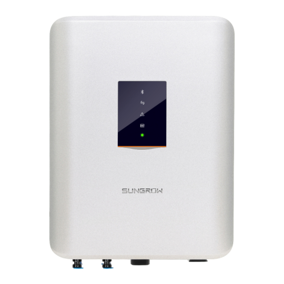
2 Product Description User Manual TN-C TN-C-S Transformer Transformer Transformer SG10KTL-M/ SG10KTL-M/ SG10KTL-M/ SG12KTL-M SG12KTL-M SG12KTL-M 2.2 Product Introduction 2.2.1 Appearance Fig. 2-2 Appearance * Pictures are indicative only. Product in kind prevail. Name Description HMI interface to indicate the present working state LED indicator panel of the inverter. -
Page 15: Dimensions
User Manual 2 Product Description 2.2.2 Dimensions Fig. 2-3 Dimensions of the inverter (in mm) 2.2.3 LED Indicator Panel As a HMI interface, the LED indicator panel on the inverter front panel indicates the present working state of the inverter. Fig. - Page 16 2 Product Description User Manual Tab. 2-1 State description of the LED indicator panel LED indicator LED color LED state Definition Bluetooth communication connected and there is not data communication No device connected to the Bluetooth Blue inverter through Bluetooth. Bluetooth communication Periodical flash...
-
Page 17: Dc Switch
User Manual 2 Product Description LED indicator LED color LED state Definition No fault occured Earth earth impedance impedance short-circuit fault occured abnormal (the device cannot connect to the grid) Both the AC and DC is powered down The DC or AC is powered on and the device is in standby Normal Periodical flash... -
Page 18: Function Description
Relays Filter Filter MPPT 2 (Boost 2) AC SPD DC SPD Fig. 2-5 Circuit diagram of SG10KTL-M/SG12KTL-M 2.3.2 Function Description Inversion function The inverter converts the DC current into grid-compatible AC current and feeds the AC current into grid. -
Page 19: Derating
When the inverter internal temperature exceeds the upper limit, the inverter will derate power output until the temperature drops within the permissible range. Over-temperature derating curve of SG10KTL-M (Vac=400V) Output Power Vmmp=470V (kVA)... - Page 20 When the grid voltage is low, the inverter will derate the output power to make sure the output current is within the permissible range. Once the grid voltage is within Vmin…600V, the inverter will derate the output power. Grid Under-voltage derating curve of SG10KTL-M Pout (Vdc=600V) (W)...
- Page 21 If the input voltage is too high, the inverter may derate the power output. The relationship between the input voltage and the power derating is shown in the figure below. High input voltage derating curve of SG10KTL-M Vac=400V 10000 9000...
- Page 22 2 Product Description User Manual High input voltage derating curve of SG12KTL-M Vac=400V 12000 10800 9600 9000 8400 7200 6000 4800 3600 2400 1200 Vin(V) 1000 1100 Fig. 2-7 Input voltage and the power derating Altitude derating When the altitude exceeds a certain value, the output power of the inverter will decrease with the increase of the altitude.
-
Page 23: Installation Flow
3 Installation Flow Fig. 3-1 shows the installation flow of the inverter and Tab. 3-1 gives a detailed explanation. Start Select mounting location Move inverter Unpacking and Inspection Read User Manual Install inverter Electrical connection Check before commissioning Commissioning Troubleshooting Success? Fig. - Page 24 3 Installation Flow User Manual Tab. 3-1 Description of installation flow Step Description Reference Select optimal installation site Move the inverter to the installation site Unpacking and inspection Read the User Manual, especially the section on “Safety Instruction” Install the inverter to the selected installation site Electrical connection;...
-
Page 25: Unpacking And Storage
Check the completeness of delivery contents according to the packing list. Check the inner contents for damage after unpacking. If any damage is found, please contact Sungrow or the forwarding company. Do not dispose of the original packaging. It is best to store the inverter in its original packaging. - Page 26 Fig. 4-2 Nameplate of Inverters *Image shown here is for reference only. Actual product you receive may differ. Item Description SUNGROW logo and product type Technical data of inverter Marks of certification institutions of inverter Company name, website and origin Tab.
-
Page 27: Scope Of Delivery
4.4 Inverter Storage Proper storage is required if the inverter is not installed immediately. Sungrow shall hold no liability for the damage of the device, in appearance or the failure of internal components, caused by improper storage of the device as specified in this manual. - Page 28 The packing should be upright. If the inverter is stored for half a year or longer, the local installer or service dept. of Sungrow should perform a comprehensive test before connecting the inverter into a PV power system.
-
Page 29: Mechanical Installation
5 Mechanical Installation 5.1 Installation Site Selection Select an optimal installation site for safe operation, long service life and outstanding performance. Take the load capacity of the wall into account. The wall (concrete wall or metal frame) should be strong enough for the weight of the inverter over a long period. ... - Page 30 5 Mechanical Installation User Manual Place the inverter at eye level for easy viewing and operation. For proper ventilation of the inverter, the lowest place of the inverter shall be no less than 450mm above the ground. Do not install the inverter upside down or leaning forward. ...
-
Page 31: Moving Inverter To Installation Site
User Manual 5 Mechanical Installation Snow Direct sunlight Direct rain fall accumulation Ensure there is enough space for convection when installing multiple inverters. It is suggest to stager the inverters. 600mm 800mm 600mm 800mm Do not install the inverter in a confined space. The inverter will not work normally if otherwise. -
Page 32: Installation Tools
5 Mechanical Installation User Manual A minimum of two people or proper moving devices should be used to move the inverter. Do not release the equipment unless it has been secured firmly. 5.3 Installation Tools Gather the following tools before installation: ... -
Page 33: Installing To Metal Frame
User Manual 5 Mechanical Installation Fig. 5-2 Dimensions of fastener for metal frame (figures in mm) Please select the appropriate length of the expansion screw according to the thickness of the wall insulation layer. The dimensions shown in the image here is for reference only. 5.4.1 Installing to Metal Frame Remove the backplate and fasteners from the packaging. -
Page 34: Installing To Concrete Wall
5 Mechanical Installation User Manual Lift the inverter above the backplate and then slide down to make sure they Step 6 match perfectly. You can use the fastener set to lock the device. 5.4.2 Installing to Concrete Wall Remove the backplate and corresponding fasteners from the packaging. Step 1 Place the backplate on the chosen concrete wall and adjust it to proper Step 2... - Page 35 User Manual 5 Mechanical Installation Lift the inverter above the backplate and then slide down to make sure they Step 6 match perfectly. You can use the fastener set to lock the device.
-
Page 36: Electrical Connection
6 Electrical Connection Once the inverter is secured to the installation site, it can be connected to the PV system. All electrical connections must comply with local regulations and related electrical rules. Improper cable connection may lead to a fatal injury or permanent damage to the device. -
Page 37: Ac Side Cable Connection
An independent three or four-pole circuit breaker is installed outside the output side of the inverter to ensure that the inverter can be disconnected safely. Inverter Type Recommended AC circuit breaker current SG10KTL-M SG12KTL-M It is not allowed to install more than one inverter per fuse or circuit breaker. -
Page 38: Grid Connection
AC Cable Requirements Select AC cables according to the following factors: Grid impedance corresponds to the specifications below to avoid accidental short-circuit or output power derating. SG10KTL-M SG12KTL-M 6.67 AC voltage without loads [V] The cable cross-sectional areas and recommended value are shown in the following table, avoiding power loss in the cables of more than 1% of the nominal power. - Page 39 User Manual 6 Electrical Connection Connecting The Inverter to Grid High voltage inside the inverter! Ensure all cables are voltage-free before electrical connection. Do not connect the AC circuit breaker until all inverter electrical connections are completed. AC cables Procedure Loosen all screws on the AC terminal lid and remove the lid.
-
Page 40: Connecting Inverter To Pv Arrays
6 Electrical Connection User Manual AC Wiring Procedure Disconnect AC circuit breaker to prevent it from inadvertently Step 1 reconnecting. Insert the AC connector into the input terminals on the bottom of Step 2 the inverter until there is an audible sound. Connect PE cable to ground. -
Page 41: Pv Input Configuration
Short-circuit Current Inverter Type Limit for Each Input Limit for Each Input SG10KTL-M 1100 V SG12KTL-M 1100V Considering the negative voltage temperature coefficient of PV module, more attention should be paid to the open-circuit voltage of PV strings when designing at the lowest ambient temperature. -
Page 42: Pv Input Connection
PV Input Connection DC cables from PV strings should be equipped with DC connectors. Sungrow provides corresponding plug connectors in the scope of delivery for quick connection of PV inputs. Pairs of MC4 DC connectors are supplied in the scope of delivery. - Page 43 User Manual 6 Electrical Connection DC Cable Connection High voltage inside the inverter! Make sure all DC and AC cables connected to the inverter are voltage-free before electrical connection. Do not connect the AC circuit breaker before electrical connection is completed.
- Page 44 6 Electrical Connection User Manual The inverter will not function properly if the DC polarities are reversed. Disconnect the DC switch. Step 7 Check the connection cable of PV string for the correct polarity and that the Step 8 open-circuit voltage does not exceed the inverter input limit 1100V, even under the lowest operating temperature.
-
Page 45: Grounding The Inverter
User Manual 6 Electrical Connection Connect other PV strings following the above-mentioned procedures. Step 10 Seal the unused DC terminals with the waterproof plugs. Step 11 6.4 Grounding the Inverter Due to the transformer-less design of the inverter, neither the DC positive pole nor the DC negative pole of the PV string can be grounded. -
Page 46: Second Protective Earth Terminal
6 Electrical Connection User Manual PV Arrays 1 Inverter 1 Inverter 2 Inverter n PV Arrays 2 PV Arrays n Mounting Frame of PV arrays Equipotential cable Grounding of PV Power System L2 L3 AC Circuit Breaker Inverter AC Grounding Electrode Grounding of Inverter AC Side Fig. -
Page 47: Rs485 Communication Connection
The ground connection of this second PE terminal cannot replace the connection of the PE terminal of the AC cables. Make sure the two PE terminals are all grounded reliably. Sungrow shall hold no liability for any possible consequences caused by ignorance of this warning. -
Page 48: Rs485 Communication System
User Manual A converter such as RS485-232 converter or Data Logger is needed to convert signal between inverter and PC. Data logger and RS485-232 converter are optional parts and can be ordered from Sungrow. RS485 RS232 6.5.2 RS485 Communication System... -
Page 49: Plc Communication Connection
APP interface. 6.5.3 PLC Communication Connection The inverter internal PLC communication module is compatible with the PLC Box provided by Sungrow. For the detailed connection information, please refer to the User Manual of the PLC Box. - Page 50 6 Electrical Connection User Manual The PLC Box is an optional device that can be ordered from Sungrow. The PLC Box conducts data communication by directly using the AC output cable of the inverter and thus saves the trouble to lay and maintain the special communication cables.
-
Page 51: Commissioning
7 Commissioning Commissioning is a critical procedure for a PV system, which can protect the system from fires, and personnel from injury and electrical shock. 7.1 Inspection before Commissioning Before starting the inverter, you should check the following items. Ambient Environment The inverter should be accessible for operation, maintenance and service. - Page 52 7 Commissioning User Manual If the conditions are OK, the inverter feeds AC power to the grid and enters into the running state. Observe the status of LED indicator panel. Step 4 LED indicator LED color LED state Definition The Bluetooth communication is connected and there is not data communication...
- Page 53 User Manual 7 Commissioning LED indicator LED color LED state Definition No fault occured Earth earth impedance impedance short-circuit fault occured (the abnormal device cannot connect to the grid) Both the AC and DC is powered down The DC or AC is powered on and Normal Periodical the device is in standby or...
-
Page 54: Disconnecting, Dismantling And Disposing The Inverter
8 Disconnecting, Dismantling and Disposing the Inverter 8.1 Disconnecting the Inverter For maintenance work or any service work, the inverter must be switched off. During normal operation, the inverter should remain switched on. Proceed as follows to disconnect the inverter from DC and AC power sources Disconnect the external AC circuit breaker or disconnect to prevent it from Step 1 accidentally reconnecting to the utility grid. -
Page 55: Disposal Of The Inverter
User Manual 8 Disconnecting, Dismantling and Disposing the Inverter 8.3 Disposal of the Inverter System owners and the O&M company are responsible for the disposal of the inverter. Some parts and devices in the inverter, such as the LED indicator panel, batteries, modules and other components, may cause environmental pollution. -
Page 56: Troubleshooting And Maintenance
If the grid voltage is within the permissible requirements. range, contact Sungrow. This is a short-term fault due to grid Grid transient voltage conditions. Wait a moment for inverter exceeds the permissible recovery. - Page 57 Sungrow. The DC component of AC Wait for inverter recovery. current exceeds inverter If the fault still occurs, contact Sungrow. limit. Check the PV strings for ground fault. Fault current leakage is If the fault occurs repeatedly, contact detected Sungrow.
- Page 58 If the fault occurs repeatedly, contact Sungrow. This is a short-term fault. Wait for inverter Bus voltage fluctuation recovery If the fault still occurs, contact Sungrow. PV1 reverse connection Check the PV1 connection. fault PV2 reverse connection Check the PV2 connection.
- Page 59 Description Troubleshooting Code Current leakage sampling Wait for inverter recovery. channel failure If the fault still occurs, contact Sungrow. If the fault occurs repeatedly, contact Current imbalance. Sungrow. Disconnect and stop the inverter. Wait for ambient temperature falls the ambient temperature to rise within the below -25 permissible range and then restart inverter.
-
Page 60: Maintenance
Check if the air inlet and outlet are normal. contents in air.) Clean the air inlet and outlet, if necessary. 9.3 Contact Sungrow Service Should you have any problems in operating on the inverter, please contact us: Service hotline: 400-880-5578 Email: service@sungrow.cn... -
Page 61: Sun Access App
10 Sun Access APP 10.1 Introduction to the System By establishing a communication connection with the inverter through Bluetooth, the Sun Access APP can access near-end maintenance to the inverter. You can check the running info, alarms and events, set the parameters, download the logs and update the firmware through the APP. -
Page 62: Logging Sun Access App
10 Sun Access APP User Manual Click “Open” after the app is installed to open the app as shown in Fig. 10-1. Step 2 You can also open the app by clicking the icon of the app in your phone desktop. - Page 63 10 Sun Access APP User Manual Fig. 10-2 Select user type Fig. 10-3 Nearby bluetooth list If you have no password, please click “login without password” to login and check certain info. The password for the regular user is 111111. Select the Bluetooth device to be connected and connect to that Bluetooth Step 3 as shown in Fig.
- Page 64 10 Sun Access APP User Manual Fig. 10-4 Device connection If the inverter is not initialized, you will enter the initialization protection Step 4 parameter quick setting interface as shown in Fig. 10-5 after the Bluetooth is connected. After setting the quick setting interface, click “Save” and the device will be initialized.
-
Page 65: Homepage
10 Sun Access APP User Manual The system interface may be different for different types of users. If you login by “login without password”, the app will not show the initialization protection parameter setting interface. The regular user can only set the country, instructions (valid for certain countries) and protection stage. -
Page 66: Run Info
10 Sun Access APP User Manual Fig. 10-7 Check the homepage info If a real-time alarm occurs in the inverter, there will be an alarm or fault icon appearing in the lower right corner of the inverter (circled by a box in the top of the interface). - Page 67 10 Sun Access APP User Manual Fig. 10-8 Run info Tab. 10-1 Description of Running Parameters Parameter Description the total PV input power Total DC power(KW) DC voltage1(V) the DC1 input voltage Input DC current1(A) the DC1 input current DC voltage2(V) the DC2 input voltage DC current2(A) the DC2 input current...
-
Page 68: History Record
10 Sun Access APP User Manual Parameter Description Negative pole voltage to Inverter negative pole voltage to ground ground(V) Inverter busbar voltage Busbar voltage(V) More In parallel resistance to ground(kΩ) Countries info Inverter selected country code 10.6 History Record Click the “History” icon from the navigation bar to view the history record interface as shown in Fig. - Page 69 10 Sun Access APP User Manual Fig. 10-10 Fault alrm records If you need to check the alarm records within a certain period of time, please click the time selection bar on the top of the interface to select a certain period of time.
-
Page 70: Power Yields Records
10 Sun Access APP User Manual Fig. 10-11 Detailed fault alarm info 10.6.2 Power Yields Records User can view various energy records: power curve, daily energy histogram, daily energy histogram, monthly energy histogram, and annual energy histogram. Tab. 10-2 Explanation of power yields records Parameter Description Show the power output from 5am to 11pm in a single day. - Page 71 10 Sun Access APP User Manual Fig. 10-12 Power curve Click the time selection bar on the top of the interface to check the power Step 2 curve of a certain time as shown in Fig. 10-13. Fig. 10-13 Power curve...
-
Page 72: Event Records
10 Sun Access APP User Manual Swipe left to check the power yields histogram as shown in Fig. 10-14. Step 3 Fig. 10-14 power yields histogram 10.6.3 Event Records Click the “Event records” to check the event record list as shown in Fig. 10-15. Fig. -
Page 73: More
10 Sun Access APP User Manual If you need to check the event records within a certain period of time, please click the time selection bar on the top of the interface to select a certain period of time. The inverter can at most record the latest 100 events. -
Page 74: System Parameters
10 Sun Access APP User Manual Fig. 10-17 Power on 10.7.2 System Parameters Click the “System parameters” to check the system parameter info and set the related parameters as shown in Fig. 10-18. Fig. 10-18 System parameter... -
Page 75: Operation Parameters
10 Sun Access APP User Manual Tab. 10-3 Explanation of system parameters Parameter Description Date Setting Time deviation between the time on the inverter and the local time of the installation site may cause data logging failure. Time Setting Please adjust inverter time according to the local time. If the accumulative value “E-total”... - Page 76 10 Sun Access APP User Manual Active & reactive power parameters Fig. 10-20 Active & reactive power parameters Tab. 10-4 Description of Active & reactive power parameters Parameter Description Default Range Active power Inverter active power limitation 110.0% 0~110% limit Set the active power change rate.
- Page 77 10 Sun Access APP User Manual Parameter Description Default Range reactive power Q-Var witch [OFF] [OFF]/ [ON] regulation function -1.000~-0.800/ Inverter output power factor +1.000 +0.800~+1.000 Inverter reactive power 0~+100%/ Q-Var limits 0.0% limitation 0~-100% Inverter provides reactive power regulation function. Use the “Q-Var switch” parameter to activate this function and select proper regulation mode.
- Page 78 10 Sun Access APP User Manual Tab. 10-6 “Q(P)” Mode Parameters Explanation Parameter Explanation Default Range Upper Power factor of point P1 in the Q(P) mode 0.9~1 curve Lower Output power of point P1 in the Q(P) 0%~50% Power* mode curve (in %) Power factor of point P2 in the Q(P) mode Lower PF Ind 0.9~1...
- Page 79 10 Sun Access APP User Manual * U1 Limit + Hysteresis < U2 Limit - Hysteresis Q/Sn Upper Q/Sn Ind Hysteresis U2 Limit Upper U limit Grid voltage Lower U limit U1 Limit Hysteresis Lower Q/Sn Cap Fig. 10-22 Reactive Power Regulation Curve in Q(U) Mode Run Time Parameters ...
- Page 80 10 Sun Access APP User Manual LVRT Parameters Set the LVRT to OFF or ON. When it is ON, the inverter can keep grid-connection for a certain time when grid fault occurs and provide reactive power for grid recovery. Fig.
-
Page 81: Protection Parameters
Fig. 10-27. User can only check the parameter in this interface. The default values of the protection parameters have been preset as per grid code of corresponding countries. To set the protection parameter, please contact Sungrow to acquire advanced password. - Page 82 10 Sun Access APP User Manual Fig. 10-27 Protection parameter For convenient protection parameter setting, the protection parameters are preset for certain countries. After country setting, select the protection stage as single or multiple and then set the corresponding protection parameter. Tab.
-
Page 83: Communication Parameters
10 Sun Access APP User Manual Parameter Default AC over-voltage level 2 protection time 0.10s AC under-frequency level 2 protection time 0.10s AC over-frequency level 2 protection time 0.10s Proceed protection recovery value after setting single-stage/multi-stage protection stage. Tab. 10-12 Description of protection recovery parameters Parameter Explanation Vmax-recover... -
Page 84: Advanced Settings
10 Sun Access APP User Manual 10.7.6 Advanced Settings Click the “Advanced Settings” to check the advanced setting interface and set the related parameters as shown in Fig. 10-29. Fig. 10-29 Advanced settings Tab. 10-14 Explanation of advanced settings Parameter Description When the PV inputs are changed, the corresponding “fault”... -
Page 85: Download The Log
10 Sun Access APP User Manual 10.7.7 Download the Log Click the “Download the log” to check the log download interface and download the logs as shown in Fig. 10-30. Fig. 10-30 Download the logs 10.7.8 Firmware Upgrade Click the “Firmware upgrade” to check the firmware upgrade interface and select the files to be upgraded as shown in Fig. -
Page 86: About Sun Access
10 Sun Access APP User Manual 10.7.9 About Sun Access Click the “About Sun Access” to check the about interface as shown in Fig. 10-32. Fig. 10-32 About Sun Access... -
Page 87: Appendix
11 Appendix 11.1 Technical Data Parameters SG10KTL-M SG12KTL-M Input Side Data Max. PV input voltage 1100V MPP voltage range 200- 950V voltage range 480 - 850V 550 - 850V nominal power No. of MPPT(s) Max. PV input current 11A/11A Max.Short-circuit... -
Page 88: Exclusion Of Liability
11 Appendix User Manual Parameters SG10KTL-M SG12KTL-M System data Max. efficiency 98.5% 98.45% CEC efficiency 98.0% Isolation method Transformerless Degree of Protection IP65 Night power consumption <2W Operating ambient -25℃ to+60℃ (>45℃ derating) temperature range Allowable relative humidity 0 - 100%... -
Page 89: About Us
The power rating of SUNGROW products covers a range from several hundred watts to large mega-watt systems. The pursuit of SUNGROW is to help our customers acquire stable and clean power with minimum cost, maximum reliability and enhanced safety. - Page 90 Sungrow Power Supply Co., Ltd. Add: No.1699 Xiyou Rd.,New & High Technology Industrial Development Zone, 230088,Hefei, P. R. China. Post Zip: 230088 Web: www.sungrowpower.com Tel: +86 551 6532 7834/6532 7845 E-mail: info@sungrow.cn Fax: +86 551 6532 7856 Specifications are subject to changes without advance notice.
Need help?
Do you have a question about the SG10KTL-M and is the answer not in the manual?
Questions and answers