Table of Contents
Advertisement
Quick Links
Advertisement
Table of Contents
Troubleshooting

Related Manuals for Sungrow SG500MX


Summary of Contents for Sungrow SG500MX
- Page 1 SG500MX PV Grid-Connected Inverter Operation Manual SG500MX-OEN-Ver11-201511...
-
Page 3: Table Of Contents
Contents About this Manual ................1 1.1 Foreword ............................1 1.2 Validity ............................1 1.3 Contents ............................1 1.4 Target Group ..........................1 1.5 How to Use This Manual......................1 1.6 Symbols Explanation ........................2 1.7 ... - Page 4 3.1.5 Start/Stop Switch ......................10 3.2 Communication Solution ..................... 11 3.2.1 RS485 Communication Solution ................11 3.2.2 Ethernet Communication Solution ................ 12 Inverter Start/Stop ................ 13 4.1 Starting the Inverter....................... 13 4.1.1 Inspection before starting the inverter ..............
- Page 5 6.12 Load Default ......................... 27 6.13 Firmware Version Checking ..................27 Parameters of LCD ................28 7.1 Communication Parameters ....................28 7.1.1 Serial Port Parameter Setting..................28 7.1.2 Ethernet Parameter Setting..................29 7.2 ...
- Page 6 9.4 Replacement of the electrical components ..............45 Troubleshooting ................46 10.1 Fault Checking ......................46 10.2 Fault and Troubleshooting of LED ................ 46 10.3 Fault and Troubleshooting on the LCD screen ..........47 10.4 ...
-
Page 7: About This Manual
1 About this Manual 1.1 Foreword Thank you for purchasing the SG500MX PV grid-connected central inverter from Sungrow Power Supply Co., Ltd.. We hope that the device will meet with your satisfaction when you use it with your PV system. Your commands and feedbacks on the performance and function of the device are very important for our further improvement. -
Page 8: Symbols Explanation
All rights reserved including the pictures, markings and symbols used. Any reproduction or disclosure, even partially, of the contents of this manual is strictly forbidden without prior written authorization of Sungrow. For user’s convenience, there are a large number of pictures in this manual. These pictures are indicative only. - Page 9 Operation Manual 1 About this Manual Symbols Explanations Risk of electric shock! Hot surface! Connection point for earth conductor Protective conductor terminal...
-
Page 10: Safety Instructions
2 Safety Instructions 2.1 Intended Usage The MX-series inverter (It will be referred to as inverter hereinafter unless otherwise specified), a central inverter without transformer, is a crucial unit in a grid-connected PV power system. Inverter is dedicated to converting direct current (DC) generated by the PV modules into alternating current (AC), which conforms to parameters of local utility grid, and feeds the alternating current into the utility grid. -
Page 11: During Operation
Operation Manual 2 Safety Instructions Lethal voltage inside the device! Respect all warning labels on the product Respect all safety instructions in this manual and other related documents. Lethal Voltage! Damage to the inverter or system fault may result in death by electric shock or fire! ... -
Page 12: Safety Warning Signs
2 Safety Instructions Operation Manual All safety instructions, warning labels and nameplate on the inverter body must be clearly visible; Replace the markings once they are damaged or unclear. 2.3.4 Safety Warning Signs Please respect the followings during installation, daily maintenance or troubleshooting of the inverter: ... -
Page 13: Lcd Parameter Setting
Operation Manual 2 Safety Instructions Instrument for measurement of the electrical parameters should be high quality instrument with sufficient measuring range. Make sure the connection and use of the instrument are correct to avoid arc and other dangerous situations. 2.3.9 LCD Parameter Setting Certain LCD settable parameters are closely related to the inverter operation, therefore these parameters can only be set after reliable evaluation of the system and inverter. -
Page 14: Others
The actual product you receive may differ. Should you have any specific requirements, please inform us. This manual may not cover all possible situations. Should a specific problem occur that is not explained in this manual, please contact Sungrow. -
Page 15: Product Description
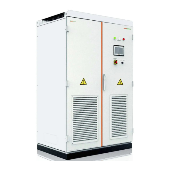
3 Product Description 3.1 Product Appearance 3.1.1 Brief Introduction The front view and main external components of the inverter are shown below. Fig. 3-1 Appearance of the Inverter Item Name Description LED Indicators 3 indicators: Power, Operation and Fault LCD Touch Screen Display data and perform control functions Press down the button in emergency occasions and inverter Emergency Stop Button... -
Page 16: Lcd Display
3 Product Description Operation Manual Possible LED combinations and the meaning are listed in the following table: LED status Description System self-checking upon energization All three LEDs are on (only POWER after self-checking) Normal power supply, inverter not connect “POWER” LED is on to the grid side parameters... -
Page 17: Communication Solution
Operation Manual 3 Product Description When you put the switch in the “stop” position, the inverter will stop through a stop command sent to the control DSP. 3.2 Communication Solution 3.2.1 RS485 Communication Solution SolarInfo Logger Inverter can communicate with SolarInfo Logger via the RS485 standard serial port. SolarInfo Logger can monitor the communication of single or multiple inverters. -
Page 18: Ethernet Communication Solution
If there is more than one inverter, the Ethernet switch is required for communication. SolarInfo Insight is used to monitor the communication. Fig. 3-6 Ethernet communication of multiple inverters The details of SolarInfo Logger and SolarInfo Insight are available on Sungrow’s website. Please download the latest product materials when necessary. -
Page 19: Inverter Start/Stop
4 Inverter Start/Stop 4.1 Starting the Inverter 4.1.1 Inspection before starting the inverter After the maintenance or service work, you may start the inverter. Inspect the following requirement before starting the inverter: All connections are done by strictly following the installation manual and circuit diagram. ... -
Page 20: Normal Stop
4 Inverter Start/Stop Operation Manual 4.2.1 Normal Stop Proceed as follows to stop the inverter during normal maintenance and service work as follows: Step 1 Stop the inverter through the stop operation on the LCD panel Turn the inverter Start/Stop switch to the “STOP” position Step 2 Open the inverter AC cabinet door and disconnect the AC switch Step 3... -
Page 21: Operation Mode
5 Operation Mode 5.1 Mode Change After being energized, inverter can switch among different modes as shown in the figure below. Fig. 5-1 Operation modes change Upv is the DC input voltage of the inverter. UpvStart is the inverter DC side startup voltage. 5.2 Operation Modes Stop This is the initial state of the inverter. - Page 22 5 Operation Mode Operation Manual Startup This is the transient process between the Initial Standby mode and the Run mode. Once the Startup mode is complete, inverter will start powering the grid. In this mode, inverter converts the DC into AC and feeds it to the grid. Inverter tracks the PV arrays’...
- Page 23 Operation Manual 5 Operation Mode Key-stop In Run mode, inverter will enter into the Key-stop mode by sending stop instruction via the LCD panel if user needs to conduct maintenance or service work. Alram Run In Warning Run mode, inverter can keep running but send warning signal. User can check the present warning information through the Working state on the LCD default screen or check the latest 100 history warning information through Function/History information/his alarm.
-
Page 24: Lcd Menu Operation
6 LCD Menu Operation 6.1 LCD Touch Screen The LCD touch screen, located at the eye-level in the front side of the inverter, is used for user to view the data and set related parameters. The LCD consists of two parts as shown in the following figure. The LEDs indicate the present working state. -
Page 25: Default Screen Introduction
LCD screen contains lots of parameters pertinent to the inverter operation. All parameter configurations must be done by appointed personnel. DO NOT modify any parameters before you fully understand this manual or consult the staff from Sungrow. 6.2.3 Backlight and Screensaver If there is no operation to the screen for 5 minutes or more, the backlight will be off. -
Page 26: Layout Of The Submenus
6 LCD Menu Operation Operation Manual Main Menu First sub-menu Second sub-menu Third sub-menu Start/Stop Start Stop Home Function Run-information Real Time Data Power curve E-histogram History-information His-event His-fault His-data His-alarn Start/Stop Start Stop Set-parameter Sys-parameter Language & Firmware Ver. Time E-total adjust Remote/Local control... -
Page 27: Language Setting
Operation Manual 6 LCD Menu Operation Tap “Function” from the default menu; Step 1 Tap “Set-parameter” and the password entering window pops out; Step 2 Tap the white edit box and a keypad pops out. Enter the password through the keypad. ←: backspace key, delete the digit input −... -
Page 28: Date And Time Setting
6 LCD Menu Operation Operation Manual Tap “Language & Firmware Ver. ” and enter into the language and firmware version sub-menu; Step 4 Select the target language. Step 5 Shortcut The language setting shortcut (A) is at the lower right side of the Home menu. Select either language by tapping the language button. -
Page 29: History Information Checking
Operation Manual 6 LCD Menu Operation Real-time data The work state, power supply mode, output power, DC voltage current, grid frequency, power factor, internal temperature, module temperature, efficiency, positive insulation resistance to the ground, AC and DC main switches states are included. Internal statistics The total power yields, amount of CO reduction, monthly power yields, total running hours... -
Page 30: History Event Checking
6 LCD Menu Operation Operation Manual alarm. 6.8.1 History Event Checking Tap “Function” from the default menu; Step 1 Tap “History-information” and enter into the history information sub-menu; Step 2 Step 3 Tap “His-event” and enter into the history event sub-menu. Up to 100 history events can be viewed from this sub-menu, with up to 5 records can be shown in one page. -
Page 31: History Alarm Checking
Operation Manual 6 LCD Menu Operation Up to 100 history faults can be viewed from this sub-menu, with up to 5 records can be shown in one page. The upper left side of the event table is the total number of the current fault records. Tap “Prev”... -
Page 32: Starting/Stopping The Inverter
6 LCD Menu Operation Operation Manual 6.10 Starting/Stopping the Inverter Usually, the inverter will start automatically when the grid-connected requirements are met. Follow either of the two ways below to start/stop the inverter through the LCD screen: Tap “Start/Stop” from the default menu. ... -
Page 33: Load Default
Operation Manual 6 LCD Menu Operation Tap the cell below the “Compensation” and the keypad appears. Enter the energy compensation by tapping the keypad; Tap “Enter” to confirm the setting. Step 5 6.12 Load Default Proceed as follows to perform the load default: Tap “Function”... -
Page 34: Parameters Of Lcd
7 Parameters of LCD 7.1 Communication Parameters Improper communication parameter configuration lead inverter communication failure! Follow strictly the instructions of the plant staff to configure the communication parameters. There are the standard RS485 communication and Network communication. User can set the communication address and protocol through the LCD screen when the hardware connection is complete and the inverter is energized. -
Page 35: Ethernet Parameter Setting
Operation Manual 7 Parameters of LCD 7.1.2 Ethernet Parameter Setting Click Network Parameter to enter the following interface. Seven parameters pertinent to the Network communication can be set. DNS address 1 and DNS address 2 can be set to the default value. Other parameters are assigned by plant staff. Set parameter with the aid of the pop-up keypad. -
Page 36: Protection Parameter
Improper parameter configuration may affect the normal operation of the inverter! Only authorized personnel can configure these parameters. Should any question or doubt occurs, please contact Sungrow. Please refer to the LCD screen for the specific setting ranges of these parameters. -
Page 37: Description Of Protection Parameters
Improper parameter configuration may affect the normal operation of the inverter! Only authorized personnel can configure these parameters. Should any question or doubt occurs, please contact Sungrow. 7.3.2 Description of Protection Parameters Descriptions of the protective parameters are shown in the following table. - Page 38 7 Parameters of LCD Operation Manual Parameter Description Unavailable Refer to Fig. 8-1Lower voltage withstand requirements, U2 LVRT tolera vol min(V) Unavailable LVRT T1(ms) Refer to Fig. 8-1Lower voltage withstand requirements, T1 LVRT T2(ms) Refer to Fig. 8-1Lower voltage withstand requirements, T2 Ratio of reactive power compensation and voltage dropping LVRT dynamic Kf factor depth during LVRT...
- Page 39 Operation Manual 7 Parameters of LCD Parameter Range Default HVRT normal vol max(%) 110~120 HVRT tolera vol max (%) 120~140 Tmax-HVRT normal(ms) 100~20000 10000 Tmax-HVRT tolera(ms) 100~5000 Active Islanding Enable/Disable Disable I leakage-pro(A) Invalid (mode disabled)/ Anti-PID mode Invalid/Suppression/Repair Suppression (mode enabled) Ins monitor measure time (S)
-
Page 40: Inverter Functions
8 Inverter Functions 8.1 Perfect Control Strategy The following three control strategies are provided for user to perform control functions and configure relevant parameters. “Remote”: The control codes can be sent only by the remote control machine. “Local”: The control codes can be sent only by the LCD screen. ... -
Page 41: How To Realize Power Limitation
Improper parameter configuration may affect the normal operation of the inverter! Only authorized personnel can configure these parameters. Should any question or doubt occurs, please contact Sungrow. User can adjust the active power output through the LCD display: Tap “ Function” from the default menu;... -
Page 42: Lvrt
Improper parameter configuration may affect the normal operation of the inverter! Only authorized personnel can configure these parameters. Should any question or doubt occurs, please contact Sungrow. 8.4 LVRT LVRT requires: PV plant can operate normally within certain voltage drop range and duration when the voltage of the grid-connected point drops due to the power system failure or disturbance;... -
Page 43: Temperature Derating
Operation Manual 8 Inverter Functions Fig. 8-2 High voltage withstand requirements The inverter meets the abovementioned requirements. 8.6 Temperature Derating When the ambient temperature is below 50℃, inverter can operates at 110% of the overload condition. When the ambient temperature reaches 55℃, inverter can keep the nominal power output. -
Page 44: Mppt
8 Inverter Functions Operation Manual 8.7 MPPT Maximum Power Point Tracking (MPPT) is a technique that the inverter uses to get the maximum power from the PV arrays. PV arrays have a complex relationship between solar irradiation, temperature and total resistance that produces a non-linear output efficiency known as the I-V curve. -
Page 45: Anti-Pid Function Setting
Sungrow inverter is... -
Page 46: Simple Troubleshooting
8 Inverter Functions Operation Manual equipped with insulation resistance monitoring function to detect the system insulation resistance in real time. If the resistance is detected to be low, it will send alarm at the first time to remind the user and prevent potential hazards. The insulation monitoring function can be divided into two kinds: ... - Page 47 Operation Manual 8 Inverter Functions “Islanding” is a potential threaten to devices and operators. If the inverter continues power supply after the grid is out of power supply, death or injury may occur to the maintainers during maintenance. When power grid fails, the inverter continues power supply.
-
Page 48: Routine Maintenance
9 Routine Maintenance Due to the effect of ambient temperature, humidity, dust and vibration, the inner components of the inverter will be aging and worn out. To ensure the system safety and maintain the efficiency of the inverter, it is necessary to carry out routine and periodic maintenance. All measures, which can help the in inverter be in good working conditions, are within the maintenance scope. - Page 49 Operation Manual 9 Routine Maintenance Item Method Interval Read out SolarInfo Logger data; Save software Once a month Save running data, parameters and logs to a disk or data a file; Check each parameter setting; Update software ...
-
Page 50: Filter Checking And Cleaning
9 Routine Maintenance Operation Manual Item Method Interval Check if the time displayed on the LCD display is time Everyone and a half display correct; year Replace the button cells on the back of the LCD panel if time is incorrect after calibration. Check the module fans inside the cabinet periodically and the fans on top of the cabinet for abnormal operation and abnormal noise. -
Page 51: Replacement Of The Electrical Components
Step 3 Reassemble the filter according to the reverse procedure shown above. Contact Sungrow to order the filter. User can cut proper filters out of the larger filter. 9.4 Replacement of the electrical components The electrical components inside the inverter must be replaced by the same components from the same manufacturer and with the same model number. -
Page 52: Troubleshooting
Fault and Troubleshooting of LED LED state Description No LED is on Disconnect the AC/DC voltage for 5 minutes. Reconnect the AC/DC voltage. If the LEDs keep off, repair or replace them. Contact Sungrow if the malfunction cannot be removed following these instructions. -
Page 53: Fault And Troubleshooting On The Lcd Screen
No power supply to the inverter. First ensure the power supply and the grid-connection are normal. Disconnect the AC/DC voltage for 5 minutes and reconnect them. If the LED keeps off, please contact Sungrow. OPERATION is off The grid is not in grid-connection state. - Page 54 Internal fault reason Wait 5 minutes for inverter auto-reconnection or disconnect first and then connect Measure the AC main switch Contact Sungrow if the fault insists Remark Stop the inverter if this fault occurs 5 times per day Fault Cntr-flt...
-
Page 55: Lcd Display Alarm Information And Troubleshooting
Fan-flt Inverter internal fan fault Possible reason Check the functionality of fan after the device is voltage-free Measure Remark Contact Sungrow DC SPD flt Fault Possible DC SPD tripping, over-voltage protection reason Measure Replace the SPD with the same model after the device is voltage-free... -
Page 56: Other Faults
10 Troubleshooting Operation Manual Fault LVRT Run Grid voltage is below 0.9Un and the LVRT function is enabled Possible reason Warn will disappear automatically when grid voltage recover normal Measure Remark CT-Unbalanced Fault Possible Current transformer (CT) on the inverter control cabinet is abnormal reason Measure Check and service the CT on the measuring board when inverter is voltage-free... - Page 57 Operation Manual 10 Troubleshooting Communication Failure with PC Check if the address and the Baud rate of the LCD are the same with that of PC. Check to ensure the circuits are properly connected and A/B is connected correctly. ...
-
Page 58: Appendix
11 Appendix 11.1 Technical Data 11.1.1 Electrical Parameters Input data (DC side) Parameter Specification Max. DC Voltage 1000Vdc Start-up voltage 500V MPP Voltage Range 460V~850V Min. DC Voltage 460V Max. DC Power 560kW Max. Input Current 1220A Output data (AC side) Parameter Specification Nominal Output Power... -
Page 59: Display And Communication
Unforeseen calamity or force majeure The use of supplied software produced by Sungrow Power Supply Co., Ltd. is subject to the following conditions: Sungrow Power Supply Co., Ltd. assumes no liability for direct or indirect damages arising from the use of SolarInfo software. -
Page 60: Contact Information
11.4 Contact Information Should you have any questions or queries about this product, please contact us through the following information. We will be more than happy to assist you! Company: Sungrow Power Supply Co., Ltd. Website: www.sungrowpower.com Email: Info@sungrow.cn; service@sungrow.cn.
Need help?
Do you have a question about the SG500MX and is the answer not in the manual?
Questions and answers