
Related Manuals for HIMA HIMatrix F2 DO 8 01


Summary of Contents for HIMA HIMatrix F2 DO 8 01
- Page 1 HIMatrix Safety-Related Controller F2 DO 8 01 Manual HIMA Paul Hildebrandt GmbH + Co KG Industrial Automation Rev. 1.01 HI 800 157 E...
- Page 2 HIMA directly. HIMA appreciates any suggestion on which information should be included in the manual. Equipment subject to change without notice. HIMA also reserves the right to modify the written material without prior notice. For further information, refer to the CD-ROM and our website http://www.hima.de and http://www.hima.com.
-
Page 3: Table Of Contents
Connections for Ethernet Communication ............. 18 3.4.2.2 Network Ports Used for Ethernet Communication ..........18 3.4.3 Reset Key ......................19 Product Data......................20 Certified HIMatrix F2 DO 8 01................21 HI 800 157 E Rev. 1.01 Page 3 of 40... - Page 4 Table of Contents F2 DO 8 01 Start-Up ..............22 Installation and Mounting ..................22 4.1.1 Connecting the Relay Outputs................22 4.1.2 Mounting the F2 DO 8 01 in Zone 2 ............... 23 Configuration ......................24 Configuring the Remote I/O with SILworX ............24 4.3.1 Parameters and Error Codes for the Relay Output ..........
-
Page 5: Introduction
F2 DO 8 01 1 Introduction Introduction This manual describes the technical characteristics of the device and its use. It also includes instructions on how to install, start up and replace it. Structure and Use of this Manual The content of this manual is part of the hardware description of the HIMatrix programmable electronic system. -
Page 6: Target Audience
ELOP II Factory Table 2: Additional Relevant Documents The latest manuals can be downloaded from the HIMA website www.hima.com. The revision index on the footer can be used to compare the current version of existing manuals with the Internet edition. -
Page 7: Formatting Conventions
F2 DO 8 01 1 Introduction Formatting Conventions To ensure improved readability and comprehensibility, the following fonts are used in this document: To highlight important parts Bold: Names of buttons, menu functions and tabs that can be clicked and used in the programming tool. For parameters and system variables Italics: Literal user inputs... -
Page 8: Operating Tips
1 Introduction F2 DO 8 01 1.3.2 Operating Tips Additional information is structured as presented in the following example: The text corresponding to the additional information is located here. Useful tips and tricks appear as follows: The tip text is located here. Page 8 of 40 HI 800 157 E Rev. -
Page 9: Safety
F2 DO 8 01 2 Safety Safety The following safety information, notes and instructions must be strictly observed. The product may only be used if all guidelines and safety instructions are adhered to. This product is operated with SELV or PELV. No imminent danger results from the product itself. -
Page 10: Residual Risk
2 Safety F2 DO 8 01 Residual Risk No imminent danger results from a HIMatrix system itself. Residual risk may result from: Faults in the engineering Faults in the user program Faults in the wiring Safety Precautions Observe all local safety requirements and use the protective equipment required on site. Emergency Information A HIMatrix system is a part of the safety equipment of a site. -
Page 11: Product Description
(IEC 61508, IEC 61511 and IEC 62061), Cat. 4 (EN 954-1) and PL e (EN ISO 13849-1). Further safety standards, application standards and test standards are specified in the certificate available on the HIMA website. Safety Function The remote I/O is equipped with safety-related relay outputs. These outputs are safely assigned their values by the connected controller via safeethernet. -
Page 12: Reaction In The Event Of A Fault
3 Product Description F2 DO 8 01 3.1.1.1 Reaction in the Event of a Fault If the device detects a faulty signal on a digital output, the affected module output is set to the safe (de-energized) state using the safety switches. If a fault in the device occurs, all digital outputs are switched off. -
Page 13: Type Label
F2 DO 8 01 3 Product Description Type Label The type plate contains the following details: Product name Bar code (1D or 2D code) Part no. Production year Hardware revision index (HW Rev.) Firmware revision index (FW Rev.) Operating voltage Mark of conformity Figure 1: Sample Type Label... -
Page 14: Assembly
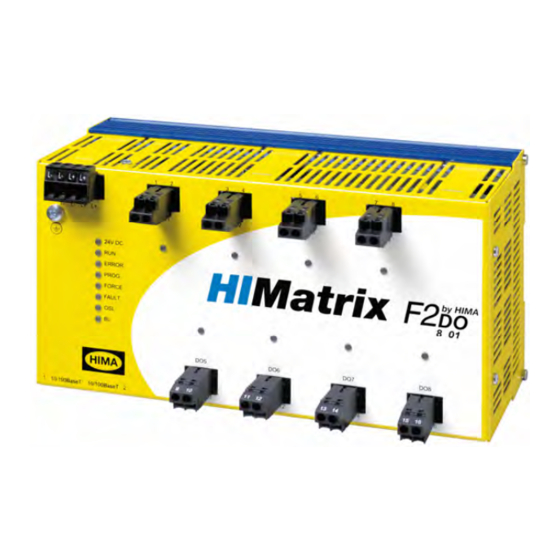
3 Product Description F2 DO 8 01 Assembly This chapter describes the layout and function of the remote I/Os, and their communication via safeethernet. 8 01 Figure 2: Front View 8 Relay Outputs Ethernet Switch Safety-Related Processor System Watchdog Figure 3: Block Diagram Page 14 of 40 HI 800 157 E Rev. -
Page 15: Led Indicators
F2 DO 8 01 3 Product Description 3.4.1 LED Indicators The light-emitting diodes (LEDs) indicate the operating state of the remote I/O. The LEDs are classified as follows: Operating Voltage LED System LEDs Communication LEDs I/O LEDs 3.4.1.1 Operating Voltage LED Color Status Description... -
Page 16: System Leds
3 Product Description F2 DO 8 01 3.4.1.2 System LEDs While the system is being booted, all LEDs are lit simultaneously. Color Status Description Green Device in RUN, normal operation A loaded user program is being executed (not with remote I/Os). Blinking Device in STOP A new operating system is being loaded. -
Page 17: Communication Leds
F2 DO 8 01 3 Product Description 3.4.1.3 Communication LEDs All RJ-45 connectors are provided with a green and a yellow LED. The LEDs signal the following states: Status Description Green Full duplex operation Blinking Collision Half duplex operation, no collision Yellow Connection available Blinking... -
Page 18: Communication
3 Product Description F2 DO 8 01 3.4.2 Communication The remote I/O communicates with the associated controller via safeethernet. 3.4.2.1 Connections for Ethernet Communication Property Description Ports 2 x RJ-45 Transfer standard 10/100/Base-T, half and full duplex Auto negotiation Auto crossover Connection socket RJ-45 IP address... -
Page 19: Reset Key
F2 DO 8 01 3 Product Description 3.4.3 Reset Key The remote I/O is equipped with a reset key. The key is only required if the user name or password for administrator access is not known. If only the IP address set for the remote I/O does not match the PADT (PC), the connection can be established with a Route add entry on the PC. -
Page 20: Product Data
3 Product Description F2 DO 8 01 Product Data General Response time ≥ 20 ms Ethernet interfaces 2 x RJ-45, 10/100BaseT (with 100 Mbit/s) with integrated switch Operating voltage 24 VDC, -15 %...+20 %, w ≤ 15 %, from a power supply unit with safe insulation in accordance with IEC 61131-2. -
Page 21: Certified Himatrix F2 Do 8 01
Class I, DIV 2, Groups A, B, C and D Class 3600, 1998 Class 3611, 1999 Class 3810, 1989 Including Supplement #1, 1995 CSA C22.2 No 142 CSA C22.2 No 213 Table 13: Certified HIMatrix F2 DO 8 01 HI 800 157 E Rev. 1.01 Page 21 of 40... -
Page 22: Start-Up
4 Start-Up F2 DO 8 01 Start-Up To start up the remote I/O, it must be mounted, connected and configured in the programming tool. Installation and Mounting The remote I/O is mounted on a 35 mm DIN rail such as described in the HIMatrix System Manual for Compact Systems. -
Page 23: Mounting The F2 Do 8 01 In Zone 2
2. The enclosure in use must be able to safely dissipate the generated heat. Depending on the output load and supply voltage, the HIMatrix F2 DO 8 01 module has a power dissipation ranging between 18 W and 46 W. -
Page 24: Configuration
4 Start-Up F2 DO 8 01 Configuration The remote I/O can be configured using a programming tool, SILworX or ELOP II Factory. Which programming tool should be used depends on the revision status of the operating system (firmware): ELOP II Factory is required for operating system versions prior to 7. SILworX is required for operating system version 7 and beyond. -
Page 25: Module Tab
F2 DO 8 01 4 Start-Up 4.3.2.1 Module Tab The Module tab contains the following system parameters. System parameter Data Description type DO.Error Code WORD Error codes for all digital outputs Coding Description 0x0001 Module fault. 0x0002 MOT test safety switch 1 faulty 0x0004 MOT test safety switch 2 faulty 0x0008... -
Page 26: Do 8: Channels Tab
4 Start-Up F2 DO 8 01 4.3.2.2 DO 8: Channels Tab The DO 8: Channels tab contains the following system parameters. System Data Description parameter type Channel no. Channel number, defined by default -> Error Code BYTE Error codes for the digital output channels [BYTE] Coding Description... -
Page 27: Configuring A Remote I/O Using Elop Ii Factory
F2 DO 8 01 4 Start-Up Configuring a Remote I/O Using ELOP II Factory 4.4.1 Configuring the Relay Outputs The signals previously defined in the Signal Editor (Hardware Management) are assigned to the individual channels (outputs) using ELOP II Factory. Refer to the System Manual for Compact Controller or the online help for more details. -
Page 28: Digital Outputs For F2 Do 8 01
4 Start-Up F2 DO 8 01 4.4.2.1 Digital Outputs for F2 DO 8 01 System Signal Description Mod.SRS [UDINT] Slot number (System Rack Slot) Mod. Type [UINT] Type of module, target value: 0x003C [60 Mod. Error Code Module error code [WORD] Coding Description... -
Page 29: Operation
F2 DO 8 01 5 Operation Operation The remote I/O can only operated together with a controller. No specific monitoring is required for remote I/Os. Handling Handling of the remote I/O during operation is not required. Diagnosis A first diagnosis results from evaluating the LEDs, see Chapter 3.4.1. The remote I/O's diagnostic history can also be read using the programming tool. -
Page 30: Maintenance
6.2.1 Loading the Operating System HIMA is continuously improving the operating system of the devices. HIMA recommends to use system downtimes to load a current version of the operating system into the devices. Refer to the release list to check the consequences of the new operation system version on the system! Load the operating system using the programming tool. -
Page 31: Decommissioning
F2 DO 8 01 7 Decommissioning Decommissioning Remove the supply voltage to decommission the device. Afterwards pull out the pluggable screw terminal connector blocks for inputs and outputs and the Ethernet cables. HI 800 157 E Rev. 1.01 Page 31 of 40... -
Page 32: Transport
8 Transport F2 DO 8 01 Transport To avoid mechanical damage, HIMatrix components must be transported in packaging. Always store HIMatrix components in their original product packaging. This packaging also provides protection against electrostatic discharge. Note that the product packaging alone is not suitable for transmission. -
Page 33: Disposal
9 Disposal Disposal Industrial customers are responsible for correctly disposing of decommissioned HIMatrix hardware. Upon request, a disposal agreement can be arranged with HIMA. All materials must be disposed of in an ecologically sound manner. HI 800 157 E Rev. 1.01... - Page 34 9 Disposal F2 DO 8 01 Page 34 of 40 HI 800 157 E Rev. 1.01...
-
Page 35: Appendix
F2 DO 8 01 Appendix Appendix Glossary Term Description Address Resolution Protocol: Network protocol for assigning the network addresses to hardware addresses Analog Input COMmunication module Cyclic Redundancy Check Digital Input Digital Output ELOP II Factory Programming tool for HIMatrix systems ElectroMagnetic Compatibility European Norm ElectroStatic Discharge... -
Page 36: Index Of Figures
Appendix F2 DO 8 01 Index of Figures Figure 1: Sample Type Label Figure 2: Front View Figure 3: Block Diagram Figure 4: Sample MAC Address Label Figure 5: Label for Ex Conditions Page 36 of 40 HI 800 157 E Rev. 1.01... -
Page 37: Index Of Tables
Table 11: Product Data Table 12: Specifications of the Relay Outputs Table 13: Certified HIMatrix F2 DO 8 01 Table 14: Terminal Assignment for the Relay Outputs Table 15: SILworX - System Parameters for Relay Outputs, Module Tab Table 16:... -
Page 38: Index
Appendix F2 DO 8 01 Index diagnosis..........29 part number ..........12 fault reaction safeethernet..........18 digital outputs ........12 SRS ............12 Page 38 of 40 HI 800 157 E Rev. 1.01... - Page 40 HIMA Paul Hildebrandt GmbH + Co KG P.O. Box 1261 68777 Brühl, Germany Tel: +49 6202 709-0 Fax: +49 6202 709-107 E-mail: info@hima.com Internet: www.hima.com (1025)
Need help?
Do you have a question about the HIMatrix F2 DO 8 01 and is the answer not in the manual?
Questions and answers