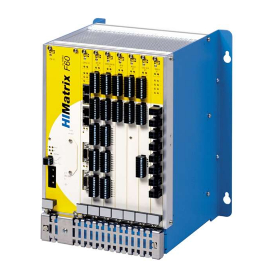
HIMA HIMatrix F60 Manual
Safety-related controller
Hide thumbs
Also See for HIMatrix F60:
- Manual (114 pages) ,
- Engineering manual (64 pages) ,
- System manual (110 pages)

Related Manuals for HIMA HIMatrix F60


Summary of Contents for HIMA HIMatrix F60
-
Page 1: Table Of Contents
HIMatrix Safety-Related Controller DI 32 01 Manual HIMA Paul Hildebrandt GmbH + Co KG Industrial Automation Rev. 2.00 HI 800 203 E... - Page 2 All HIMA products mentioned in this manual are protected by the HIMA trade-mark. Unless noted otherwise, this also applies to other manufacturers and their respective products referred to herein. ® ® ® ® ® HIMax , HIMatrix , SILworX , XMR...
-
Page 3: Table Of Contents
DI 32 01 Table of Contents Table of Contents Introduction Structure and Use of this Manual Target Audience Formatting Conventions 1.3.1 Safety Notes 1.3.2 Operating Tips Safety Intended Use 2.1.1 Environmental Requirements 2.1.2 ESD Protective Measures Residual Risk Safety Precautions Emergency Information Product Description Safety Function... - Page 4 Table of Contents DI 32 01 Configuration with ELOP II Factory 4.4.1 Configuring the Inputs 4.4.2 Signals and Error Codes for the Inputs 4.4.3 Digital Inputs Operation Handling Diagnosis Maintenance Faults Maintenance Measures 6.2.1 Loading the Operating System 6.2.2 Proof Test Decommissioning Transport Disposal...
-
Page 5: Introduction
Decommissioning Transport Disposal The HIMatrix F60 is available for the programming tools SILworX and ELOP II Factory. Which programming tool can be used, depends on the processor operating system of the HIMatrix F60, refer to the following table:... -
Page 6: Target Audience
HI 800 006 E Table 2: Additional Relevant Documents The latest manuals can be downloaded from the HIMA website at www.hima.com. The revision index on the footer can be used to compare the current version of existing manuals with the Internet edition. -
Page 7: Formatting Conventions
DI 32 01 1 Introduction Formatting Conventions To ensure improved readability and comprehensibility, the following fonts are used in this document: Bold To highlight important parts. Names of buttons, menu functions and tabs that can be clicked and used in the programming tool. Italics For parameters and system variables Courier... -
Page 8: Operating Tips
1 Introduction DI 32 01 1.3.2 Operating Tips Additional information is structured as presented in the following example: The text corresponding to the additional information is located here. Useful tips and tricks appear as follows: The tip text is located here. Page 8 of 38 HI 800 203 E Rev. -
Page 9: Safety
DI 32 01 2 Safety Safety All safety information, notes and instructions specified in this document must be strictly observed. The product may only be used if all guidelines and safety instructions are adhered to. This product is operated with SELV or PELV. No imminent risk results from the product itself. The use in Ex-zone is permitted if additional measures are taken. -
Page 10: Residual Risk
2 Safety DI 32 01 Residual Risk No imminent risk results from a HIMatrix system itself. Residual risk may result from: Faults related to engineering Faults related to the user program Faults related to the wiring Safety Precautions Observe all local safety requirements and use the protective equipment required on site. -
Page 11: Product Description
(IEC 61508, IEC 61511 and IEC 62061), Cat. 4 and PL e (EN ISO 13849-1) and SIL 4 (EN 50126, EN 50128 and EN 129). Further safety standards, application standards and test standards are specified in the certificates available on the HIMA website. Safety Function 3.1.1 Safety-Related Inputs The module is equipped with safety-related inputs.The module is equipped with safety-related... -
Page 12: Equipment, Scope Of Delivery
3 Product Description DI 32 01 The digital outputs are pulsed. This allows monitoring of the wires to the digital inputs of the F60 DI 32 01 or F60 DIO 24/16 01 module. A fault reaction is triggered if one of the following faults occurs: ... -
Page 13: Structure
DI 32 01 3 Product Description Structure This chapter describes the layout and function of the module. 3.4.1 Block Diagram Test I/O Bus 32 Channels Figure 3: Block Diagram HI 800 203 E Rev. 2.00 Page 13 of 38... -
Page 14: Front View
3 Product Description DI 32 01 3.4.2 Front View DI 32 Figure 4: Front View Page 14 of 38 HI 800 203 E Rev. 2.00... -
Page 15: Status Indicators
DI 32 01 3 Product Description 3.4.3 Status Indicators Color Status Description Green Operating voltage present No operating voltage Module faulty or external faults Reaction as dictated by the diagnosis No module faults and / or no channel faults Table 5: Status Indicators 3.4.4 I/O LEDs... -
Page 16: Product Data
3 Product Description DI 32 01 Product Data General 15 %, Operating voltage 24 VDC, -15...+20 %, r from a power supply unit with safe insulation, in accordance with IEC 61131-2 Operating data 3.3 VDC / 0.05 A 24 VDC / 0.2 A Ambient temperature 0...+60 °C Storage temperature... -
Page 17: Start-Up
Installation and Mounting The module is mounted in the subrack of the modular HIMatrix F60 system. When laying cables (long cables, in particular), take appropriate measures to avoid interference, e.g., by separating the signal lines from the power lines. - Page 18 4 Start-up DI 32 01 Use the following terminals to connect the inputs: Terminal Designation Function Supply for inputs 1...7 Digital input 1 Digital input 2 Digital input 3 Digital input 4 Digital input 5 Digital input 6 Digital input 7 EGND Ground Terminal...
-
Page 19: Surges On Digital Inputs
DI 32 01 4 Start-up Terminal Designation Function EGND Ground EGND Ground EGND Ground EGND Ground Table 10: Terminal Assignment for the Inputs 4.1.2.1 Surges on Digital Inputs Due to the short cycle time of the HIMatrix systems, a surge pulse as described in EN 61000-4-5 can be read in to the digital inputs as a short-term high level. -
Page 20: Mounting The Di 32 01 In Zone 2
When mounting the device, observe the special conditions specified in the following section. Specific Conditions X 1. Mount the HIMatrix F60 controller in an enclosure that meets the EN 60079-15 requirements and achieves a type of protection of at least IP54, in accordance with EN 60529. Provide the... -
Page 21: Configuration
DI 32 01 4 Start-up Configuration The module can be configured using a programming tool, SILworX or ELOP II Factory. Which programming tool should be used, depends on the revision status of the operating system (firmware): SILworX is required for CPU OS V7 and higher. ... -
Page 22: Configuration With Silworx
4 Start-up DI 32 01 Configuration with SILworX In the Hardware Editor, the controller is represented with the following modules: one processor module (CPU) one communication module (COM) 6 slots available for I/O modules To insert I/O modules, drag them from the module list onto an available slot. Double-click the module to open the Detail View with the corresponding tabs. -
Page 23: Tab Module
DI 32 01 4 Start-up 4.3.2.1 Tab Module The Module tab contains the following system parameters: System parameter Data type Description DI Number of Pulsed USINT Number of pulsed outputs (supply outputs) Outputs Coding Description No output planned for SC/OC detection Output channel 1 planned for SC/OC detection... -
Page 24: Tab Di 32 01: Channels
4 Start-up DI 32 01 4.3.2.2 Tab DI 32 01: Channels The DI 32 01: -Channels tab contains the following system parameters: System parameter Data type Description -> Error Code [BYTE] BYTE Error codes for the digital input channels Coding Description 0x01 Fault in the analog input module... -
Page 25: Digital Inputs
DI 32 01 4 Start-up 4.4.3 Digital Inputs System signal Description Mod.SRS [UDINT] Slot number (System.Rack.Slot) Mod. Type [UINT] Type of module, target value: 0xF807 [63 495 Mod. Error Code Error codes for the module [WORD] Coding Description 0x0000 I/O processing, if required with errors see other error codes 0x0001 No I/O processing (CPU not in RUN) - Page 26 4 Start-up DI 32 01 System signal Description DI[xx].Pulsed Source channel for pulsed supply Channel [USINT] Coding Description Input channel Pulse of the 1st DO channel Pulse of the 2nd DO channel Pulse of the 8th DO channel DI Pulse Delay Waiting time for line control (detection of short-circuits or cross-circuits) [10E-6 s] [UINT] SC/OC (short-circuits/open-circuits)
-
Page 27: Operation
DI 32 01 5 Operation Operation The module runs within a HIMatrix base plate and does not require any specific monitoring. Handling Handling of the controller during operation is not required. Diagnosis A first diagnosis results from evaluating the LEDs, see Chapter 3.4.3. The module diagnostic history can also be read using the programming tool. -
Page 28: Maintenance
Perform the proof test 6.2.1 Loading the Operating System HIMA is continuously improving the operating system of the F60 central module. HIMA recommends to use system downtimes to load the current version of the operating system into the F60 controller. -
Page 29: Decommissioning
DI 32 01 7 Decommissioning Decommissioning Remove the supply voltage of the PS 01 supply module to decommission the module. Afterwards pull out the pluggable screw terminal connector blocks for inputs and outputs and the Ethernet cables. HI 800 203 E Rev. 2.00 Page 29 of 38... -
Page 30: Transport
8 Transport DI 32 01 Transport To avoid mechanical damage, HIMatrix components must be transported in packaging. Always store HIMatrix components in their original product packaging. This packaging also provides protection against electrostatic discharge. Note that the product packaging alone is not suitable for transport. -
Page 31: Disposal
9 Disposal Disposal Industrial customers are responsible for correctly disposing of decommissioned HIMatrix hardware. Upon request, a disposal agreement can be arranged with HIMA. All materials must be disposed of in an ecologically sound manner. HI 800 203 E Rev. 2.00... - Page 32 9 Disposal DI 32 01 Page 32 of 38 HI 800 203 E Rev. 2.00...
-
Page 33: Appendix
DI 32 01 Appendix Appendix Glossary Term Description Address resolution protocol: Network protocol for assigning the network addresses to hardware addresses Analog input Analog output Communication module Cyclic redundancy check Digital input Digital output ELOP II Factory Programming tool for HIMatrix systems Electromagnetic compatibility European norm Electrostatic discharge... -
Page 34: Index Of Figures
Appendix DI 32 01 Index of Figures Figure 1: Line Control Figure 2: Sample Type Label Figure 3: Block Diagram Figure 4: Front View Figure 5: Label for Ex Conditions Page 34 of 38 HI 800 203 E Rev. 2.00... -
Page 35: Index Of Tables
DI 32 01 Appendix Index of Tables Table 1: Programming Tools for HIMatrix F60 Table 2: Additional Relevant Documents Table 3: Environmental Requirements Table 4: Available Variants Table 5: Status Indicators Table 6: I/O LEDs Table 7: Product Data Table 8:... -
Page 36: Index
Appendix DI 32 01 Index block diagram..........13 front view ............ 14 diagnosis.............27 safety function ..........11 fault reaction specifications..........16 digital inputs ..........11 surge ............19 Page 36 of 38 HI 800 203 E Rev. 2.00... - Page 38 HIMA Paul Hildebrandt GmbH + Co KG P.O. Box 1261 68777 Brühl, Germany Phone: +49 6202 709-0 Fax: +49 6202 709-107 E-mail: info@hima.com Internet: www.hima.com (1334)
Need help?
Do you have a question about the HIMatrix F60 and is the answer not in the manual?
Questions and answers