HIMA HIMatrix F60 Engineering Manual
Himatrix system automation devices
Hide thumbs
Also See for HIMatrix F60:
- Manual (114 pages) ,
- System manual (110 pages) ,
- Safety manual (72 pages)

Related Manuals for HIMA HIMatrix F60


Summary of Contents for HIMA HIMatrix F60
- Page 1 Industrial-Automation System HIMatrix Engineering Manual HIMA Paul Hildebrandt GmbH + Co KG HI 800 101 JEA Industrial Automation...
- Page 2 For this reason, HIMA does not offer any warranties nor assume legal responsibility nor any liability for pos- sible consequences of any errors in this manual. HIMA appreciates any correspondence noting potential errors.
-
Page 3: About This Manual
The reproduction of the contents of this publication (either in its entirety or in a part) is not permitted without the written permission of HIMA. All rights and technical modifications reserved. © HIMA Paul Hildebrandt GmbH + Co KG P. O. Box 1261 D - 68777 Bruehl near Mannheim... - Page 4 HI 800 101 HIMatrix Engineering Manual Additional System Documentation The following documentation is also available for configuring HIMatrix systems: Name Contents Document no. Part no. D = German E = English Safety functions of HI 800 022 (D) pdf file HIMatrix Safety Manual* HIMatrix systems...
-
Page 5: Terminology
HI 800 101 HIMatrix Engineering Manual Terminology Term Definition Analog Input Analog Input/Output Analog Output Communication Module Central Processing Unit Digital Input Digital Input/Output Digital Output Electromagnetic Compatibility Field Bus Function Block Diagram Fault Tolerance Time International Electrotechnical Commission Line Control Multiple fault occurrence time Non-Safety-related Protocol Object Linking and Embedding... - Page 6 HI 800 101 HIMatrix Engineering Manual HIMatrix Product Overview Compact devices For detailed descriptions of the devices listed below and their specifications see the corre- sponding Data sheets and the System Manual of the Compact Systems. Compact device Properties Interfaces 8 digital channels, 2 Ethernet ports, configurable as inputs or outputs...
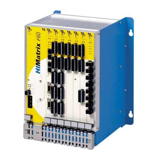
- Page 7 HI 800 101 HIMatrix Engineering Manual Modular device F60 For a detailed description of the hardware of the F60 and all applicable modules see the cor- responding Data sheets and the System Manual Modular System F60. Modular device Properties Interfaces Modular system housing, on CPU 01 module F60, GEH 01...
-
Page 8: Table Of Contents
HI 800 101 HIMatrix Engineering Manual Contents Page About this Manual..................1 Terminology ....................3 Certification...................8 Notes for Danger and Use ..............9 Notes for Danger................9 Notes for Use ..................9 Installation of HIMatrix Devices ............10 Mechanical ..................10 Installation of Controllers ..............10 3.2.1 Installation .................10 3.2.1.1 Cable routing................10 3.2.2 Air Circulation ................12... - Page 9 HI 800 101 HIMatrix Engineering Manual 5.3.2 Mounting of HIMA Field Bus Communication Modules.....33 5.3.2.1 System Requirements...............33 5.3.2.2 Display of the actual Versions of the Operating Systems..33 Wiring ....................34 5.4.1 Safeethernet, Ethernet ..............34 5.4.1.1 Interface Elements ..............35 5.4.1.2 Specified Cables ...............35 5.4.1.3 RJ 45 Connector ...............36...
-
Page 10: Certification
Automation, software and information technology Am Grauen Stein 51105 Köln Certificate and test report No. 968/EZ 128.14/07 Safety-related automation devices HIMatrix F60, F20, F35, F31, F30, F3 DIO 20/8 01, RIO-NC International standards: IEC 61508, Teile 1-7: 2000 IEC 61511: 2004 EN 954-1: 1996... -
Page 11: Notes For Danger And Use
HI 800 101 HIMatrix Engineering Manual Notes for Danger and Use This manual contains specially highlighted advices that indicate safety requirements: Notes for Danger Important information regarding situations or operations. Failure to observe these instructions could cause personal injury and/or damage to property. These notes •... -
Page 12: Installation Of Himatrix Devices
Chapter 3.3) must be checked. Mechanical The modular HIMatrix F60 controller has two perpendicular mounting links each of which has two slotted holes for fastening. They must be installed on a flat base. When installing the F60 make sure that it is fastened in place with no mechanical distortion. - Page 13 HI 800 101 HIMatrix Engineering Manual 20/8 01 20 mm 20/8 01 Minimum clearances for HIMatrix Fxx and Remote I/O (Compact devices) Minimum clearances for HIMatrix F60 Figure 1: Minimum clearances at installation 11 of 61...
-
Page 14: Air Circulation
HI 800 101 HIMatrix Engineering Manual The following installation is required so that Notes • HIMatrix devices are not subject to heat from other equipment with high heat dissipation, • devices with high EMC interference do not interfere with HIMatrix devices. Note the information provided by the manufacturer. - Page 15 HI 800 101 HIMatrix Engineering Manual If more than two HIMatrix devices (even when the minimum vertical clearance of 100 mm is retained) are installed one above the other, additional measures for ventilation are required to ensure even temperature distribution. The illustration below left shows the minimum clearances if no spacers are used for the rails: Note HIMatrix devices can only...
-
Page 16: Assembly Heights
HI 800 101 HIMatrix Engineering Manual 3.2.3 Assembly Heights Because of the connectors for communication and I/O level the HIMatrix devices require the assembly heights shown in the table below. With compact devices they apply from the fixing rail: HIMatrix device Assembly height 270 mm F1 DI 16 01... -
Page 17: Heat Dissipation
HI 800 101 HIMatrix Engineering Manual 3.3.1 Heat Dissipation An enclosed case must be designed to allow the heat generated inside it to be dissipated from its surface. The type and site of installation must be selected to allow heat dissipation. The heat output of the installed components determines the design of the ventilation compo- nents. -
Page 18: Temperature State/Operating Temperature
HI 800 101 HIMatrix Engineering Manual Example: Calculation of power dissipation P for controller F35 • Idle current consumption of the controller: 0.75 A at 24 V • 8 outputs with current consumption of each 1 A at 2 V •... -
Page 19: Earth And Shield
HI 800 101 HIMatrix Engineering Manual Earth and Shield 3.5.1 Earthing the System Voltage 24 VDC All devices of the HIMatrix family must be operated with power supply units that comply with the SELV (Safety Extra Low Voltage) or PELV (Protective Extra Low Voltage) requirements. A function earth is provided to improve the electromagnetic compatibility (EMC). -
Page 20: Emc Protection
HI 800 101 HIMatrix Engineering Manual The shield clamp may not be used as a strain relief for the connected cable. 3.5.4 EMC Protection Windows in the case in which the device is installed are permitted. Increased EMC interferences outside the standard limit values require appropriate meas- ures. -
Page 21: Configuring The Hardware
Therefore the HIMatrix F60, F35 and F3 AIO 8/4 01 were tested and certificated according to EN54 and NFPA72 for use in fire alarm systems and fire extinguish systems. In these sys- tems it is necessary that on demand the active state is used for controlling the danger (fur- ther details see chapter 4.5). -
Page 22: Short-Circuit Characteristics Of The Output Channels
HI 800 101 HIMatrix Engineering Manual Short-Circuit Characteristics of the Output Channels In the event of a short-circuit in one output channel the HIMatrix automation devices switch off the affected channel. In the event of multiple short-circuits the channels are switched off individually in accordance to their power consumption. -
Page 23: Using The F35 Controller In The Zone
HI 800 101 HIMatrix Engineering Manual Using the F35 Controller in the Zone 2 (EG guideline 94/9/EG, ATEX) The F35 controller is suitable for installation in zone 2. The corresponding declaration of con- formity can be found in the Data sheet HIMatrix F35. For this mounting the following mentioned special conditions have to be regarded. -
Page 24: Use In Central Fire Alarm Systems
HI 800 101 HIMatrix Engineering Manual Use in Central Fire Alarm Systems All HIMatrix systems with analog inputs can be used for central fire alarm systems in accor- dance with DIN EN 54-2 and NFPA 72. The application program must fulfill the functions laid down for central fire alarm systems according to the cited standards. - Page 25 HI 800 101 HIMatrix Engineering Manual For an explicit line break monitoring (at de-energized outputs DO) a transmitter supply addi- tionally to the analog inputs is necessary (see scheme below): HIMatrix Sx / Tx 26.4 V Field terminal Series HIMatrix Actuator Field terminal Diode...
-
Page 26: Communication
(invalid configuration). Order the activation code in time! Protocols F31 02 Safeethernet HIMA OPC Server Modbus TCP Master Modbus TCP Slave Send/Receive TCP EtherNet/IP COM User Task Modbus Master RS485... -
Page 27: Field Bus Interfaces Of The Controller
After buying a license you can get a new activation code via the homepage http://himatrix.hima.com. For further information please contact the HIMA support: Phone: +49 6202 709 185 or –424 or via E-mail: support@hima.com Composition of the part number 98.22xy.. -
Page 28: Ethernet Communication
HI 800 101 HIMatrix Engineering Manual Ethernet Communication 5.2.1 Communication via Switches The switch integrated into each system for safeethernet or Ethernet communication can be seen on the block diagrams. • In contrast to a hub, a switch is able to store data packets for a short period of time in order to establish a temporary connection between two communication partners (transmitter/receiver) for the transfer of data. -
Page 29: Ethernet/Ip
For the communication between HIMatrix controllers via Ethernet the safety-related HIMA peer-to-peer protocol should be used. Further informations about the TCP S/R protocol you will find in the corresponding manual and/or in the online help of ELOP II Factory. -
Page 30: Sntp
Using the SNTP Protocol (simple network time protocol), the time of the HIMA resources can be synchronized via Ethernet. The current time can be polled in defined time intervals via the Ethernet from a HIMA re- source or a PC, which are configured as an SNTP Server. -
Page 31: Configuration Of The Ethernet Interfaces
HI 800 101 HIMatrix Engineering Manual 5.2.8 Configuration of the Ethernet Interfaces For HIMatrix devices in the register "Extended" the parameters "Speed Mode” and “Flow- Control Mode” must be set to “Autoneg”. The option “Activate Extended Settings” must be set in order that the parameters are activated (see Figure 6: Properties of the COM). Figure 6: Properties of the COM The parameters ARP, MAC Learning, IP Forwarding, Speed Mode and Flow-Control Mode are explained in detail in the online help of ELOP II Factory. - Page 32 HI 800 101 HIMatrix Engineering Manual Name Description Port Number of port as on device; per port only one configuration is possible. Value range: 1..n, depending on the resource Speed [Mbit/s] 10 MBit/s: Data rate 10 MBit/s 100 MBit/s: Data rate 100 MBit/s Autoneg (10/100): Automatic setting of the baud rate Default: Autoneg Flow-Control...
-
Page 33: Connections For Safeethernet, Ethernet/Networking Example
HI 800 101 HIMatrix Engineering Manual 5.2.9 Connections for safeethernet, Ethernet/Networking Example For the networking via safeethernet or Ethernet the devices are equipped – depending on the design – with two or four connections arranged on the lower and upper side panels of the case or on the front side (e.g. -
Page 34: Field Bus Communication
FB1 and FB2 are not functional. The mounting of the communication modules is only permitted by Note HIMA, otherwise the guarantee of the controller will be nullified. No unlock code is necessary for unlocking a communication module at Profibus and Inter- bus. -
Page 35: Mounting Of Hima Field Bus Communication Modules
HI 800 101 HIMatrix Engineering Manual 5.3.2 Mounting of HIMA Field Bus Communication Modules 5.3.2.1 System Requirements Only controllers with hardware reversion 02 can be equipped with communication module CM-PROFIBUS-DP master or CM-INTERBUS master. The modules CM-PROFIBUS-DP slave and CM-RS485 can be used on controllers with previous revisions. An update of the COM operating system is necessary in this case. -
Page 36: Wiring
HI 800 101 HIMatrix Engineering Manual Wiring 5.4.1 Safeethernet, Ethernet Industrial standard cables can be subjected to extreme mechanical stresses. For Ethernet communication Cat 5 cable (twisted pair or star-quad cable) or better is used. The controllers communicate at 100 Mbit/s (Fast Ethernet) in full-duplex mode. They have "auto cross-over"... -
Page 37: Interface Elements
HI 800 101 HIMatrix Engineering Manual Configuring a network with switches ("Switched Ethernet") has the following advantages: • Very fast packet transfer between the collision areas, • Significant increase of data throughput with full-duplex mode, • Prevention of collisions allows deterministic operation. 5.4.1.1 Interface Elements When connecting a controller to the Ethernet communication, interface elements, such as ®... -
Page 38: Rj 45 Connector
HI 800 101 HIMatrix Engineering Manual 5.4.1.3 RJ 45 Connector For direct Ethernet plug connections without interface elements connectors such as the ® IP 20 Data Plug (manufacturer Harting can be used. The cable can be assembled quickly by crimping the conductors; special tools are not required. - Page 39 HI 800 101 HIMatrix Engineering Manual Patch cable Controllers with integrated switch or components connected to a switch must be connected with a (1:1) patch cable (see following scheme). Figure 14: Patch cable 10BaseT/100BaseT Figure 15: Patch cable 1000BaseT Assignment and color codes for RJ45 plugs Core pair Pins EIA/TIA...
-
Page 40: Switches
HI 800 101 HIMatrix Engineering Manual Figure 16: Pin assignment 1:1 patch cable according to EIA/ITA 568B Figure 17: Pin assignment crossover cable according to EIA/ITA 568B 5.4.1.4 Switches To span distances of more than 100 m with Ethernet communication for example the ®... -
Page 41: Field Buses
Figure 18: Wiring and bus termination for PROFIBUS-DP As option to the shown 90º bus connectors, also straight and 45º offset connectors are avail- able from HIMA. Wiring and bus termination The incoming and outgoing data cable is connected within the bus connector. Branch lines are avoided and the connector can be plugged off from a controller without interruption of da- ta line. -
Page 42: Modbus Master/Slave Communication
In non-time-critical applications up to 126 devices (with repeater) are possible. Further informations you will find in Manual HIMA PROFIBUS-DP master (HI 800 008). 5.4.2.3 MODBUS Master/Slave Communication The total length of a bus at MODBUS can be up to 1200 m. Repeaters are needed for greater distances. -
Page 43: Interbus
HI 800 101 HIMatrix Engineering Manual 5.4.2.4 INTERBUS INTERBUS has been designed as fast sensor / actuator bus for transmitting process data in industrial environments. The INTERBUS is a single master system, i.e. all participants of an INTERBUS ring are con- trolled by one INTERBUS master (controller board). -
Page 44: Configuration Of The Software
HI 800 101 HIMatrix Engineering Manual Configuration of the Software Supported Data Types The following data types in ELOP II Factory can be used for HIMatrix controllers: BOOL, SINT, INT, DINT, USINT, UINT, UDINT, REAL, LREAL, TIME, BYTE, WORD, DWORD. Further informations about the supported data types and functions you will find in the manual HI 800 355. -
Page 45: Required Signals
HI 800 101 HIMatrix Engineering Manual The FAULT LED on the front panel of the controller flashes, the inputs are set to 0-signal and an (analyzable) error code is generated if the following errors occur: • Cross connection between two parallel lines, •... -
Page 46: Configuration For Pulsed Outputs
HI 800 101 HIMatrix Engineering Manual The following table contains the used switch signals of the example: Signal name Type Description Initial Remarks value Switch_1_1pulsed BOOL Value Switch 1 first and Switch_1_2pulsed BOOL Value second contact Switch_2_1pulsed BOOL Value Switch 2 first and Switch_2_2pulsed BOOL Value... -
Page 47: Configuration Example
HI 800 101 HIMatrix Engineering Manual 7.2.3 Configuration Example 7.2.3.1 Principle Method of Signal Assignment With the use of the software ELOP II Factory the previously via signal editor defined signals (hardware management) could be assigned to the single existing hardware inputs and out- puts. -
Page 48: Assignment Of The Signals To The Inputs And Their Error Codes46
HI 800 101 HIMatrix Engineering Manual DI [07] could have used T1 and DI [08] correspondingly T2. The allocation depends on the hardware configuration. 7.2.3.3 Assignment of the Signals to the Inputs and their Error Codes Figure 24: Assignment of the Signals to the Inputs and their Error Codes The relevant error code must also be evaluated for every usable signal DI[xx].Value. - Page 49 HI 800 101 HIMatrix Engineering Manual LS1+ Figure 26: Scheme for Line Monitoring at F35 RP = resistor parallel to the contact (= 6000 Ohm in this example) RS = resistor in series to the contact and RP (= 3900 Ohm in this example) RL = wiring resistance (= 0 Ohm in this example) RI = input resistance of digital input = 6900 Ohm DI = digital input...
- Page 50 HI 800 101 HIMatrix Engineering Manual The table shows that the gaps between Ulb, Uoc, Ucc and Usc increase with a rising voltage for LS+. In this example 18 V is considered as the worst case for LS+ (this value will be monitored in the logic) and the gaps between Ulb, Uoc, Ucc and Usc are sufficient to differ the several cases which can occur.
- Page 51 HI 800 101 HIMatrix Engineering Manual Figure 28: Function block – error conditions In this example an error is generated when the voltage of the LS+ is below 18 V and when the gaps between short-circuit, closed contact, open contact and line break are lower than 300 digits (3V).
- Page 52 HI 800 101 HIMatrix Engineering Manual Figure 30: Function block – limit for line break, short-circuit, open and closed contact The input resistance of a digital input is 6900 Ohm. 50 of 61...
-
Page 53: Line Monitoring At F3 Dio 16/8 01
HI 800 101 HIMatrix Engineering Manual Line Monitoring at F3 DIO 16/8 01 7.4.1 Parameterization of Line Monitoring at 2-Pole Connection For all corresponding system signals of line monitoring initial Note values have to be set. Therefore all needed or wanted configurations of system signals (see Table 19) must be set first in ELOP II Factory, then the application program must be compiled and at last the program must be transferred to the controller. - Page 54 HI 800 101 HIMatrix Engineering Manual Signal name Type Description Default value Couple of common reference DO[01][02].in pairs BOOL (DO- outputs build common reference potential) Couple 1 = Channel 1 [01] and channel 2 [02] DO[01][02].in pairs=1 Line monitoring with reduced voltage channel1 BOOL DO[01].LS 1 = reduced signal voltage level...
-
Page 55: Line Monitoring For Lamp Loads And Inductive Loads
HI 800 101 HIMatrix Engineering Manual Figure 32: Setting the parameters for line monitoring (Outputs F3 DIO 16/8 01) Figure 33: Setting the error codes for the outputs (Inputs F3 DIO 16/8 01) For monitoring the outputs for each channel two error codes (DO+ and DO- output, DO[xx].+Error Code and DO[xx].-Error Code) can be evaluated. -
Page 56: Line Monitoring With Reduced Voltage For Resistive, Capacitive Loads
HI 800 101 HIMatrix Engineering Manual 7.4.1.2 Line Monitoring with Reduced Voltage for Resistive, Capacitive Loads For line monitoring a 10 V signal is switched on in the output circuit for the duration of the monitoring time. This kind of line monitoring is designed for resistive or resistive capacitive loads. -
Page 57: Table Of Configurations For Digital Outputs
HI 800 101 HIMatrix Engineering Manual 7.4.2 Table of Configurations for Digital Outputs All permissible configurations for digital outputs accepted by ELOP II Factory are listed in the following table. Additional system signals have no influence on further variations (e.g. signal DO[xx].LS with reduced voltage). -
Page 58: Commissioning, Maintenance, Repairs
HI 800 101 HIMatrix Engineering Manual Commissioning, Maintenance, Repairs This chapter must be read carefully before doing any commissioning, maintenance, modifi- cations and repairs in order not to affect or endanger the safety of HIMatrix systems and their functions. Only personnel who have the knowledge of ESD protective measures are permitted to carry out system modifications/upgrades to the system wiring. -
Page 59: Replacement Of Modules
The relevant system manual contains a description of the replacement procedure. A change of the buffer battery must only be executed by the HIMA service. If the customer opens the device this will nul- lify the guarantee and the certification. -
Page 60: Repair Of Controllers And Modules
Repair of Controllers and Modules The operator may not repair controllers and modules in HIMatrix systems. Defective devices must be returned to HIMA for repair after being tested by the operator with a brief description of the fault. Equipment that has a safety certificate is safety-relevant. The validity of the certificate will expire if unauthorized repairs are made on safety-related controllers and modules of the HIMatrix system. -
Page 61: Operating Conditions
HI 800 101 HIMatrix Engineering Manual Operating Conditions The devices were developed in compliance with the requirements of the following standards for EMC, climate and environment: IEC/EN 61131-2 Programmable Controllers, Part 2 Equipment Requirement and Tests IEC/EN 61000-6-2 Generic Standards, Part 6-2 Immunity for Industrial Environments IEC/EN 61000-6-4 Generic Emission Standard... -
Page 62: Mechanical Conditions
HI 800 101 HIMatrix Engineering Manual Mechanical Conditions The most important tests and limit values for mechanical conditions are listed in the following table: Mechanical Tests IEC/EN 61131-2 Chapter 6.3.5 Vibration test, operating: 5...9 Hz / 3.5 mm 9...150 Hz / 1 g 6.3.5.1 Immunity vibration test: 10...150 Hz, 1 g, EUT operating, 10 cycles per axis... -
Page 63: Voltage Supply
HI 800 101 HIMatrix Engineering Manual Voltage Supply The most important tests and limit values for the voltage supply of the equipment are listed in the following table: Verification of DC Power Supply Characteristics IEC/EN 61131-2 Chapter 6.3.7 The power supply must meet alternatively the following standards: IEC/EN 61131-2 or SELV (Safety Extra Low Voltage) or... - Page 64 HIMA ...the safe decision. HIMA Paul Hildebrandt GmbH + Co KG Industrial Automation Postfach 1261 • D - 68777 Bruehl Phone: (+49) 6202 709-0 • Fax: (+49) 6202 709-107 E-mail: info@hima.com • Internet: www.hima.com (0908)
Need help?
Do you have a question about the HIMatrix F60 and is the answer not in the manual?
Questions and answers