Page 1
HIMatrix Safety-Related Controller F3 DIO 16/8 01 Manual HIMA Paul Hildebrandt GmbH + Co KG Industrial Automation Rev. 2.00 HI 800 177 E...
Page 2
All HIMA products mentioned in this manual are protected by the HIMA trade-mark. Unless noted otherwise, this also applies to other manufacturers and their respective products referred to herein. ® ® ® ® ® HIMax , HIMatrix , SILworX , XMR...
Network Ports Used for Ethernet Communication 3.4.3 Pulsed Outputs 3.4.4 Reset Key 3.4.4.1 Ampacity of the Digital Outputs Product Data 3.5.1 Product Data F3 DIO 16/8 014 Certified HIMatrix F3 DIO 16/8 01 HI 800 177 E Rev. 2.00 Page 3 of 60...
Page 4
Table of Contents F3 DIO 16/8 01 Start-up Installation and Mounting 4.1.1 Installation and Terminals of the Digital Inputs 4.1.2 Surges on Digital Inputs 4.1.3 Installation and Terminals of the Digital Inputs 4.1.3.1 Overview of Configuration Variants for the Digital Outputs 4.1.4 Pulsed Outputs 4.1.5...
Page 5
F3 DIO 16/8 01 Table of Contents Decommissioning Transport Disposal Appendix Glossary Index of Figures Index of Tables Index HI 800 177 E Rev. 2.00 Page 5 of 60...
Page 6
Table of Contents F3 DIO 16/8 01 Page 6 of 60 HI 800 177 E Rev. 2.00...
Structure and Use of this Manual The content of this manual is part of the hardware description of the HIMatrix programmable electronic system. This manual is organized in the following main chapters: ...
HI 800 006 E Table 2: Additional Relevant Documents The latest manuals can be downloaded from the HIMA website at www.hima.com. The revision index on the footer can be used to compare the current version of existing manuals with the Internet edition.
F3 DIO 16/8 01 1 Introduction Formatting Conventions To ensure improved readability and comprehensibility, the following fonts are used in this document: To highlight important parts. Bold Names of buttons, menu functions and tabs that can be clicked and used in the programming tool.
1 Introduction F3 DIO 16/8 01 1.3.2 Operating Tips Additional information is structured as presented in the following example: The text corresponding to the additional information is located here. Useful tips and tricks appear as follows: The tip text is located here. Page 10 of 60 HI 800 177 E Rev.
This product is operated with SELV or PELV. No imminent risk results from the product itself. The use in Ex-Zone is permitted if additional measures are taken. Intended Use HIMatrix components are designed for assembling safety-related controller systems. When using the components in the HIMatrix system, comply with the following general requirements. 2.1.1 Environmental Requirements...
Observe all local safety requirements and use the protective equipment required on site. Emergency Information A HIMatrix system is a part of the safety equipment of a site. If a device or a module fails, the system enters the safe state.
The remote I/O is available in various model variants for SILworX and ELOP II Factory, see Table 4. Remote I/Os are connected to individual HIMax or HIMatrix controllers via safeethernet. They are used to extend the I/O level, but are not able to run any user program by themselves.
3 Product Description F3 DIO 16/8 01 The remote I/O reads back the state of the unbuffered power sources and if an overload occurs, it switches off. The power sources are protected with current limiting components. Unbuffered Power Source 1 A Current Limiting Buffered Power Source Terminal Number 40 mA Current Limiting...
F3 DIO 16/8 01 3 Product Description 3.1.1.1 Reaction in the Event of a Fault If the device detects a fault on a digital input, the user program processes a low level in accordance with the de-energized to trip principle. The device activates the FAULT LED.
3 Product Description F3 DIO 16/8 01 3.1.3 Safety-Related Digital Outputs The state (HIGH, LOW) of each output is signaled by an individual LED (HIGH, LOW). The following block diagram shows how the 2-pole digital outputs are connected: & DO1+ DOn+ &...
F3 DIO 16/8 01 3 Product Description 3.1.4 Line Diagnosis with Digital Outputs The remote I/O is provided with a line diagnosis (short-circuits and open-circuits) for the digital outputs. Line diagnosis of the digital outputs is only possible when used in a 2-pole configuration.
3 Product Description F3 DIO 16/8 01 3.1.4.2 Line Diagnosis for Ohmic, Capacitive Loads To diagnose the line for ohmic and capacitive loads, the remote I/O sends a 10 V test pulse to the output circuit for the duration of the monitoring time. This type of line diagnosis is particularly recommended for ohmic and ohmic capacitive loads.
F3 DIO 16/8 01 3 Product Description Equipment, Scope of Delivery The following table specifies the available remote I/O variants: Designation Description F3 DIO 16/8 01 Remote I/O (16 digital inputs, 8 2-pole digital outputs, 2 pulsed outputs) Operating temperature: 0...+60 °C, for ELOP II Factory programming tool F3 DIO 16/8 01 Remote I/O (16 digital inputs, 8 2-pole digital outputs, 2 pulsed...
3 Product Description F3 DIO 16/8 01 Type Label The type plate contains the following details: Product name Bar code (1D or 2D code) Part no. Production year Hardware revision index (HW Rev.) Firmware revision index (FW Rev.) ...
F3 DIO 16/8 01 3 Product Description Structure This chapter describes the layout and function of the remote I/Os, and their communication via safeethernet. S+ S+ S+ S+ S- S- S- S- 
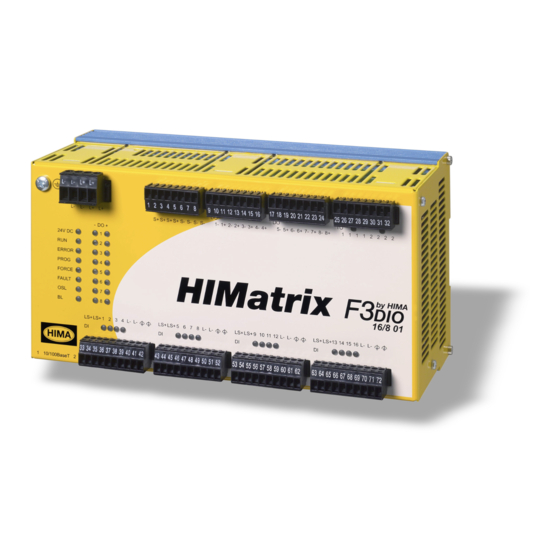
Figure 7: Front View 16 Digital Inputs 2 Pulsed outputs Safety-Related Processor System (CPU) 8 Digital Outputs, 2-Pole (DO+, DO-) Switch...
3 Product Description F3 DIO 16/8 01 3.4.1 LED Indicators The light-emitting diodes (LEDs) indicate the operating state of the remote I/O. The LEDs are classified as follows: Operating voltage LED System LEDs Communication LEDs I/O LEDs 3.4.1.1 Operating Voltage LED Color...
F3 DIO 16/8 01 3 Product Description 3.4.1.3 Communication LEDs All RJ-45 connectors are provided with a small green and a yellow LEDs. The LEDs signal the following states: Status Description Green Full duplex operation Blinking Collision Half duplex operation, no collision Yellow Connection available Blinking...
3 Product Description F3 DIO 16/8 01 3.4.2 Communication The remote I/O communicates with the associated controller via safeethernet. 3.4.2.1 Connections for Ethernet Communication Property Description Port 2 x RJ-45 Transfer standard 10BASE-T/100BASE-Tx, half and full duplex Auto negotiation Auto crossover IP address Freely configurable Subnet mask...
F3 DIO 16/8 01 3 Product Description 3.4.3 Pulsed Outputs The digital pulsed outputs can be used to detect short-circuits and open-circuits on digital inputs, e.g., on EMERGENCY STOP button complying with Cat. 4 and PL e in accordance with EN ISO 13849-1.
3 Product Description F3 DIO 16/8 01 Product Data General Response time ≥ 10 ms Ethernet interfaces 2 x RJ-45, 10BASE-T/100BASE-Tx with integrated switch Operating voltage 24 VDC, -15...+20 %, r ≤ 15 %, from a power supply unit with safe insulation in accordance with IEC 61131-2 Current input max.
F3 DIO 16/8 01 3 Product Description Digital outputs Number of outputs 8 (non-galvanically separated) 2-pole switching DO+ 2 A (inrush current typ. 10 A at 2 ms) DO- 2 A (inrush current typ. 10 A at 2 ms) Output voltage ≥...
3 Product Description F3 DIO 16/8 01 Certified HIMatrix F3 DIO 16/8 01 Test institute Standard, Scope EMC, ATEX Zone 2 TÜV IEC 61508 1-7:2000 up to SIL 3 IEC 61511:2004 EN ISO 13849-1:2008 up to Cat. 4 und PL e UL Underwriters ANSI/UL 508, NFPA 70 –...
To start up the remote I/O, it must be mounted, connected and configured in the programming tool. Installation and Mounting The remote I/O is mounted on a 35 mm DIN rail such as described in the HIMatrix System Manual for Compact Systems. When laying cables (long cables, in particular), take appropriate measures to avoid interference, e.g., by separating the signal lines from the power lines.
4.1.2 Surges on Digital Inputs Due to the short cycle time of the HIMatrix systems, a surge pulse as described in EN 61000-4-5 can be read in to the digital inputs as a short-term high level. The following measures ensure proper operation in environments where surges may occur: 1.
F3 DIO 16/8 01 4 Start-up 4.1.3.1 Overview of Configuration Variants for the Digital Outputs The following table specifies all configuration variants permitted for the digitals outputs. Additional system signals have no influence on other variants (e.g., Signal DO[xx].SC monitoring with reduced voltage). With improper parameter setting, a diagnostic entry (IOA Wrong Initial Data) is generated.
Cable Plugs Cable plugs attached to the pin headers of the devices are used to connect to the power supply and to the field zone. The cable plugs are included within the scope of delivery of the HIMatrix devices and modules.
2. The enclosure in use must be able to safely dissipate the generated heat. Depending on the output load and supply voltage, the HIMatrix F3 DIO 16/8 01 has a power dissipation ranging between 13 W and 31 W.
4 Start-up F3 DIO 16/8 01 Configuration The remote I/O can be configured using a programming tool, SILworX or ELOP II Factory. Which programming tool should be used, depends on the revision status of the operating system (firmware): SILworX is required for CPU OS V7 and higher. ...
F3 DIO 16/8 01 4 Start-up 4.3.2.1 Tab: Module The Module tab contains the following system parameters: System parameter Data Description type DI Number of USINT Number of pulsed outputs (supply outputs) Pulsed Channels Coding Description No pulsed output planned for SC/OC detection Pulsed output 1 planned for SC/OC detection...
4 Start-up F3 DIO 16/8 01 4.3.2.2 Tab: DI 16 LC: Channels The DI 16 LC: Channels tab contains the following system parameters. System Signal Data Description type Channel no. Channel number, defined by default -> Error Code [BYTE] BYTE Error codes for the digital input channels Coding Description...
F3 DIO 16/8 01 4 Start-up 4.3.3 Digital Outputs of F3 DIO 16/8 01 The following table presents the statuses and parameters for the output module (DO 8 03) in the same order given in the SILworX Hardware Editor. 4.3.3.1 Tab: Module The Module tab contains the following system parameters: System parameter...
4 Start-up F3 DIO 16/8 01 System parameter Data Description type DO.[xx][xx].in pairs BOOL Common ground for each pair (DO- outputs form the common ground) Coding Description FALSE No common ground for each pair TRUE No common ground for each pair Default value: 0 Pair 1 = Channel 1 [01] and channel 2 [02] Pair 2 = Channel 3 [03] and channel 4 [04]...
F3 DIO 16/8 01 4 Start-up 4.3.3.2 Tab: DO 8 03: Channels The DO 8 03: Channels tab contains the following system parameters. System parameter Data Description type Channel no. Channel number, defined by default -> + Error Code WORD Error codes for the digital output channels DO+ [WORD] Error codes for the digital output channels DO-...
4 Start-up F3 DIO 16/8 01 4.3.4 Pulsed Outputs for F3 DIO 16/8 01 The following table presents the statuses and parameters for the pulse module (DO 2 01) in the same order given in the SILworX Hardware Editor. 4.3.4.1 Tab: Module The Module tab contains the following system parameters: System parameter...
F3 DIO 16/8 01 4 Start-up Configuration with ELOP II Factory 4.4.1 Configuring the Inputs and Outputs The signals previously defined in the Signal Editor (Hardware Management) are assigned to the individual channels (inputs and outputs) using ELOP II Factory. Refer to the System Manual for Compact Systems or the online help for more details.
4 Start-up F3 DIO 16/8 01 4.4.3 Digital Inputs of F3 DIO 16/8 01 System Signal Description Mod.SRS [UDINT] Slot number (System Rack Slot) Mod. Type [UINT] Type of module, target value: 0x00E2 [226 Mod. Error Code [WORD] Module error code 0x0000 I/O processing, if required with errors, see other error codes...
F3 DIO 16/8 01 4 Start-up System signal Description DI Pulse Delay [10E-6 s] Waiting time for line control (detection of short-circuits or cross- [UINT] circuits) SC/OC (short-circuits/open-circuits) Table 30: ELOP II Factory - Digital Input System Signals 4.4.4 Digital Outputs of F3 DIO 16/8 01 System signal Description Mod.SRS [UDINT]...
4 Start-up F3 DIO 16/8 01 System signal Description DO[xx].+Error Code Error codes for the digital output channels DO+ DO[xx].-Error Code Error codes for the digital output channels DO- [WORD] 0x0001 Fault in the digital output module 0x0002 Channel shutdown due to overload 0x0004 Error while reading back the digital outputs 0x0008...
F3 DIO 16/8 01 4 Start-up 4.4.5 Pulsed Outputs for F3 DIO 16/8 01 System Signal Description Mod.SRS [UDINT] Slot number (System Rack Slot) Mod. Type [UINT] Type of module, target value: 0x00D3 [211 Mod. Error Code [WORD] Module error code 0x0000 I/O processing, if required with errors see other error codes...
4 Start-up F3 DIO 16/8 01 Configuration of Line Diagnosis 4.5.1 Line Diagnosis for Lamp Loads and Inductive Loads To detect short-circuits, a 24 V pulse (normal voltage level) is sent to the output circuit for the duration of 500 µs. After this time, a 10 V pulse is sent to detect open-circuits for the duration of the monitoring time.
A direct connection of the DO+ output to the external L- via the load or a connection of DO- output to external L- via the load is not permitted! Inductive loads may be connected with no free-wheeling diode on the actuator. However, HIMA strongly recommends connecting a protective diode directly to the actuator.
4 Start-up F3 DIO 16/8 01 4.6.2 2-Pole Connection The DO+ output and DO- output of a channel are required for 2-pole applications. In each channel, the DO+ output is permanently assigned to DO- output. In this case, 8 channels with 16 outputs are available. To allow 2-pole connection, the corresponding channels must be configured using the DO[xx].2-Pole system signal.
F3 DIO 16/8 01 4 Start-up 4.6.3 2-Pole Connection to Common Ground (3-pole Connection) 2-pole channels can be interconnected on a common ground to allow line diagnosis, e.g., with motors (dual motor drivers) or dual valves. The common ground is created using the DO- outputs of the channels concerned.
5 Operation F3 DIO 16/8 01 Operation The remote I/O can only operated together with a controller. No specific monitoring is required for remote I/Os. Handling Handling of the remote I/O during operation is not required. Diagnosis A first diagnosis results from evaluating the LEDs, see Chapter 3.4.1. The remote I/O writes diagnostic entries in the diagnostic memory of the connected controller.
For more information, refer to the programming tool documentation. 6.2.2 Proof Test HIMatrix devices and modules must be subjected to a proof test in intervals of 10 years. For more information, refer to the Safety Manual (HI 800 023 E). HI 800 177 E Rev. 2.00...
7 Decommissioning F3 DIO 16/8 01 Decommissioning Remove the supply voltage to decommission the device. Afterwards pull out the pluggable screw terminal connector blocks for inputs and outputs and the Ethernet cables. Page 52 of 60 HI 800 177 E Rev. 2.00...
Transport To avoid mechanical damage, HIMatrix components must be transported in packaging. Always store HIMatrix components in their original product packaging. This packaging also provides protection against electrostatic discharge. Note that the product packaging alone is not suitable for transport.
9 Disposal F3 DIO 16/8 01 Disposal Industrial customers are responsible for correctly disposing of decommissioned HIMatrix hardware. Upon request, a disposal agreement can be arranged with HIMA. All materials must be disposed of in an ecologically sound manner. Page 54 of 60...
Analog input Analog output Communication module Cyclic redundancy check Digital input Digital output ELOP II Factory Programming tool for HIMatrix systems Electromagnetic compatibility European norm Electrostatic discharge Fieldbus Function block diagrams Fault tolerance time ICMP Internet control message protocol: Network protocol for status or error messages...
9 Disposal F3 DIO 16/8 01 Index of Figures Figure 1: Connections to Safety-Related Digital Inputs Figure 2: Exemplary Structure of Buffered and Unbuffered Power Source Figure 3: Exemplary Structure of Buffered and Unbuffered Power Source Figure 4: Line Control Figure 5: Block Diagram for 2-pole Digital Outputs Figure 6:...
F3 DIO 16/8 01 Appendix Index of Tables Table 1: Programming Tools for HIMatrix Remote I/Os Table 2: Additional Relevant Documents Table 3: Environmental Requirements Table 4: Available Variants Table 5: Operating Voltage LED Table 6: System LEDs Table 7:...
Need help?
Do you have a question about the HIMatrix and is the answer not in the manual?
Questions and answers