
Related Manuals for HIMA HIMatrix


Summary of Contents for HIMA HIMatrix
- Page 1 HIMatrix Safety-Related Controller DO 8 01 Manual HIMA Paul Hildebrandt GmbH + Co KG Industrial Automation Rev. 1.00 HI 800 207 E...
- Page 2 HIMA directly. HIMA appreciates any suggestion on which information should be included in the manual. Equipment subject to change without notice. HIMA also reserves the right to modify the written material without prior notice. For further information, refer to the CD-ROM and our website http://www.hima.de and http://www.hima.com.
-
Page 3: Table Of Contents
DO 8 01 Table of Contents Table of Contents Introduction ............5 Structure and Use of this Manual................. 5 Target Audience..................... 6 Formatting Conventions ..................7 1.3.1 Safety Notes ......................7 1.3.2 Operating Tips ......................8 Safety ..............9 Intended Use ......................9 2.1.1 Environmental Requirements................... - Page 4 Table of Contents DO 8 01 Operation .............. 23 Handling ........................ 23 Diagnosis ......................23 Maintenance ............24 Faults........................24 Maintenance Measures ..................25 6.2.1 Loading the Operating System ................25 6.2.2 Proof Test....................... 25 Decommissioning ..........26 Transport .............. 27 Disposal ..............
-
Page 5: Introduction
Structure and Use of this Manual The content of this manual is part of the hardware description of the HIMatrix programmable electronic system. This manual is organized in the following main chapters:... -
Page 6: Target Audience
ELOP II Factory Table 2: Additional Relevant Documents The latest manuals can be downloaded from the HIMA website www.hima.com. The revision index on the footer can be used to compare the current version of existing manuals with the Internet edition. -
Page 7: Formatting Conventions
DO 8 01 1 Introduction Formatting Conventions To ensure improved readability and comprehensibility, the following fonts are used in this document: To highlight important parts Bold: Names of buttons, menu functions and tabs that can be clicked and used in the programming tool. For parameters and system variables Italics: Literal user inputs... -
Page 8: Operating Tips
1 Introduction DO 8 01 1.3.2 Operating Tips Additional information is structured as presented in the following example: The text corresponding to the additional information is located here. Useful tips and tricks appear as follows: The tip text is located here. Page 8 of 34 HI 800 207 E Rev. -
Page 9: Safety
The use in Ex-Zone is permitted if additional measures are taken. Intended Use HIMatrix components are designed for assembling safety-related controller systems. When using the components in the HIMatrix system, comply with the following general requirements 2.1.1 Environmental Requirements... -
Page 10: Residual Risk
Observe all local safety requirements and use the protective equipment required on site. Emergency Information A HIMatrix system is a part of the safety equipment of a site. If a device or a module fails, the site adopts the safe state. -
Page 11: Product Description
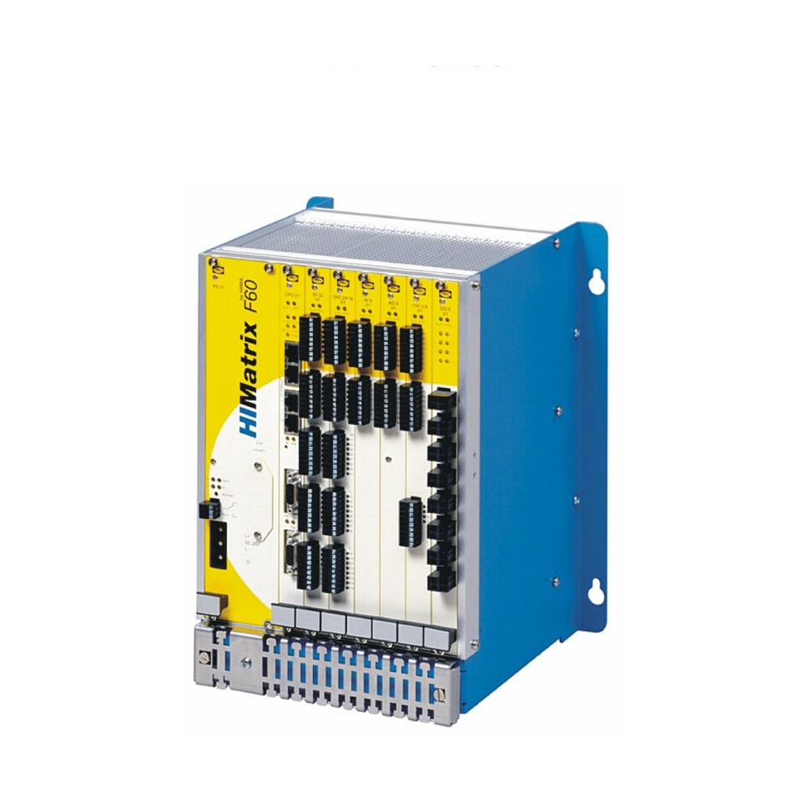
3 Product Description Product Description Do 8 01 is a plug-in module with 8 outputs for the modular F60 HIMatrix system. The module can be inserted in the F60 subrack's slot 3...8 as many times as required. Slots 1 and 2 are reserved for the power supply module and CPU module, respectively. -
Page 12: Type Label
3 Product Description DO 8 01 Type Label The type plate contains the following details: Product name Bar code (1D or 2D code) Part no. Production year Hardware revision index (HW Rev.) Firmware revision index (FW Rev.) Operating voltage Mark of conformity Figure 1: Sample Type Label Page 12 of 34... -
Page 13: Assembly
DO 8 01 3 Product Description Assembly This chapter describes the layout and function of the plug-in module. 3.4.1 Block Diagram I/O Bus 8 Relay Outputs Status Indicators Figure 2: Block Diagram HI 800 207 E Rev. 1.00 Page 13 of 34... -
Page 14: Front View
3 Product Description DO 8 01 3.4.2 Front View DO 8 RUN ERR Figure 3: Front View Page 14 of 34 HI 800 207 E Rev. 1.00... -
Page 15: Status Indicators
DO 8 01 3 Product Description 3.4.3 Status Indicators Color Status Description Green Operating voltage present No operating voltage Module faulty or external faults Reaction as dictated by the diagnosis No module faults and / or no channel faults Table 5: Status Indicators 3.4.4 I/O LEDs... -
Page 16: Table 8: Specifications For The Relay Outputs
3 Product Description DO 8 01 Relay outputs Number 8 potential-free normally open contact Execution 2 safety relays with forcibly guided contacts, 1 standard relay Switching voltage ≥ 6 V, ≤ 250 VAC / 250 VDC Switching current ≥ 10 mA, ≤ 3 A internally fused with 3.15 A fuse breaking capacity: 100 A Switching capacity AC... -
Page 17: Start-Up
To start up the controller, it must be mounted, connected and configured in the programming tool. Installation and Mounting The module is mounted in the subrack of the modular HIMatrix F60 system. 4.1.1 Mounting and Removing the Modules To mount and remove the modules, the connection cable clamp terminals must be unplugged. -
Page 18: Connecting The Relay Outputs
4 Start-Up DO 8 01 4.1.2 Connecting the Relay Outputs The use of shielded cables is not required, but improves the EMC conditions significantly. To allow the connection of the clamps to the earth grid of the F60, the diameter of the cable shielding should not exceed 12 mm. -
Page 19: Configuration
DO 8 01 4 Start-Up Configuration The DO 8 01 module can be configured using a programming tool, SILworX or ELOP II Factory. Which programming tool should be used depends on the revision status of the operating system (firmware): ELOP II Factory is required for operating system versions prior to 7. SILworX is required for operating system version 7 and beyond. -
Page 20: Parameters And Error Codes For The Output
4 Start-Up DO 8 01 4.3.1 Parameters and Error Codes for the Output The following tables specify the system parameters that can be read and set for the outputs, including the corresponding error codes. In the user program, the error codes can be read using the variables assigned within the logic. -
Page 21: Do 8 01_1: Channels Tab
DO 8 01 4 Start-Up 4.3.2.2 DO 8 01_1: Channels Tab The DO 8 01_1: DO Channels tab contains the following system variables: System Data type Description parameter -> Error Code BYTE Error codes for the digital output channels Coding Description 0x01 Fault in the digital output module... -
Page 22: Digital Outputs
4 Start-Up DO 8 01 4.4.3 Digital outputs System Signal Description Mod.SRS [UDINT] Slot number (System.Rack.Slot) Mod. Type [UINT] Type of module, target value: 0xF906 [63750 Mod. Error Code Error codes for the module [WORD] Coding Description 0x0000 I/O processing, if required with errors 0x0001 No I/O processing (CPU not in RUN) 0x0002... -
Page 23: Operation
DO 8 01 5 Operation Operation The module runs within a HIMatrix base plate and does not require any specific monitoring. Handling Handling of the controller during operation is not required. Diagnosis A first diagnosis results from evaluating the LEDs, see Chapter 3.4.3. -
Page 24: Maintenance
Maintenance No maintenance measures are required during normal operation. If a device or module fails, replace it with an identical type or an alternative type which is admitted by HIMA. Only the manufacturer is authorized to repair the device/module. Faults Refer to Chapter 3.1.1.1, for more information on the fault reaction of the outputs. -
Page 25: Maintenance Measures
For more information, refer to the programming tool documentation. 6.2.2 Proof Test Test the HIMatrix modules every 10 years. For more information, refer to the Safety Manual (HI 800 003). With safety-related applications, the relay module must be rebuilt every 3 years (offline proof test, see IEC/EN 61508-4, Section 3.8.5). -
Page 26: Decommissioning
7 Decommissioning DO 8 01 Decommissioning Remove the supply voltage to decommission the module. Afterwards pull out the pluggable screw terminal connector blocks for inputs and outputs and the Ethernet cables. Page 26 of 34 HI 800 207 E Rev. 1.00... -
Page 27: Transport
Transport To avoid mechanical damage, HIMatrix components must be transported in packaging. Always store HIMatrix components in their original product packaging. This packaging also provides protection against electrostatic discharge. Note that the product packaging alone is not suitable for transmission. -
Page 28: Disposal
9 Disposal DO 8 01 Disposal Industrial customers are responsible for correctly disposing of decommissioned HIMatrix hardware. Upon request, a disposal agreement can be arranged with HIMA. All materials must be disposed of in an ecologically sound manner. Page 28 of 34... -
Page 29: Appendix
Address Resolution Protocol: Network protocol for assigning the network addresses to hardware addresses Analog Input COMmunication module Cyclic Redundancy Check Digital Input Digital Output ELOP II Factory Programming tool for HIMatrix systems ElectroMagnetic Compatibility European Norm ElectroStatic Discharge FieldBus Function Block Diagrams Field Termination Assembly Fault Tolerance Time... -
Page 30: Index Of Figures
Appendix DO 8 01 Index of Figures Figure 1: Sample Type Label Figure 2: Block Diagram Figure 3: Front View Page 30 of 34 HI 800 207 E Rev. 1.00... -
Page 31: Index Of Tables
DO 8 01 Appendix Index of Tables Table 1: HIMatrix System Variants Table 2: Additional Relevant Documents Table 3: Environmental Requirements Table 4: Part Numbers Table 5: Status Indicators Table 6: I/O LEDs Table 7: Product Data Table 8: Specifications for the Relay Outputs... -
Page 32: Index
Appendix DO 8 01 Index diagnosis..........23 part number ..........11 fault reaction specifications ........... 15 digital outputs ........11 Page 32 of 34 HI 800 207 E Rev. 1.00... - Page 34 HIMA Paul Hildebrandt GmbH + Co KG P.O. Box 1261 68777 Brühl, Germany Tel: +49 6202 709-0 Fax: +49 6202 709-107 E-mail: info@hima.com Internet: www.hima.com (1014)
Need help?
Do you have a question about the HIMatrix and is the answer not in the manual?
Questions and answers