Table of Contents
Advertisement
Available languages
Available languages
AUTOMATISMO ELETTROMECCANICO PER BARRIERA VEICOLARE
ELECTROMECHANICAL CONTROL DEVICE FOR VEHICULAR BARRIERS
AUTOMATISME ELECTROMECANIQUE POUR BARRIERE POUR VÉHICULES
ELEKTROMECHANISCHER ANTRIEB FÜR FAHRZEUGSCHRANKEN
AUTOMATISMOS ELECTROMECANICOS PARA BARRÉRAS VEHICULAR
ELEKTROMECHANISCH AUTOMATISERINGSSYSTEEM VOOR SLAGBOOM
Attenzione! Leggere attentamente le "Avvertenze" all'interno! Caution! Read "Warnings" inside carefully! Attention! Veuillez lire attentivement les Avertissements qui se trouvent à l'intérieur!
Achtung! Bitte lesen Sie aufmerksam die „Hinweise" im Inneren! ¡Atención¡ Leer atentamente las "Advertencias" en el interior! Let op! Lees de "Waarschuwingen" aan de binnenkant zorgvuldig!
Advertisement
Table of Contents

Related Manuals for BFT GIOTTO BT A 30-60S U


Summary of Contents for BFT GIOTTO BT A 30-60S U
- Page 1 AUTOMATISMO ELETTROMECCANICO PER BARRIERA VEICOLARE ELECTROMECHANICAL CONTROL DEVICE FOR VEHICULAR BARRIERS AUTOMATISME ELECTROMECANIQUE POUR BARRIERE POUR VÉHICULES ELEKTROMECHANISCHER ANTRIEB FÜR FAHRZEUGSCHRANKEN AUTOMATISMOS ELECTROMECANICOS PARA BARRÉRAS VEHICULAR ELEKTROMECHANISCH AUTOMATISERINGSSYSTEEM VOOR SLAGBOOM Attenzione! Leggere attentamente le “Avvertenze” all’interno! Caution! Read “Warnings” inside carefully! Attention! Veuillez lire attentivement les Avertissements qui se trouvent à l’intérieur! Achtung! Bitte lesen Sie aufmerksam die „Hinweise“...
-
Page 2: Sicurezza Generale
in movimento e tenere lontano le persone finché AVVERTENZE PER L’UTILIZZATORE ( I ) non è completamente chiusa. Porre cura quando si ATTENZIONE! Importanti istruzioni di sicurezza. aziona lo sblocco se presente, poiché una tapparella Leggere e seguire attentamente le Avvertenze aperta potrebbe cadere rapidamente in presenza e le Istruzioni che accompagnano il prodotto di usura o rotture. -
Page 3: General Safety
for future reference and hand them on to any or manufacturer of the door. new users. - When cleaning the outside, always cut off mains This product is meant to be used only for the power. purpose for which it was explicitly installed. - Keep the photocells’... -
Page 4: Allgemeine Sicherheit
qualifié et expérimenté (monteur professionnel) est réparée. En cas de panne ou de mauvais fonctionne- ment de l’automatisation, mettre l’automatisation conforme aux normes reconnues de la technique et des prescriptions de sécurité. hors tension, éviter toute tentative de réparation Si l’automatisation est montée et utilisée correcte- ou d’intervention directe et s’adresser uniquement ment, elle garantit la sécurité... -
Page 5: Seguridad General
der Technik sowie den Sicherheitsbestimmungen, zeigevorrichtungen sauber. Stellen Sie sicher, dass falls es von qualifiziertem Fachpersonal (professio- die Sicherheitsvorrichtungen nicht durch Zweige oder Sträucher beeinträchtigt werden. neller Installateur) ordnungsgemäß installiert wird. - Benutzen Sie die Automatisierung nicht, falls sie Bei ordnungsgemäßer Installation und Benut- Reparatureingriffe erforderlich macht. -
Page 6: Algemene Veiligheid
lador profesional). matización, abstenerse de cualquier intento de La automatización, si se instala y utiliza de manera reparación o intervención directa y recurrir sólo a correcta, cumple con los estándares de seguridad personal cualificado y experto (instalador profesio- para el uso. Sin embargo es conveniente respetar nal) para la necesaria reparación y mantenimiento. - Page 7 Het automatiseringssysteem, indien juist geïnsta- geleiders, kan gevaren veroorzaken. De installatie lleerd en gebruikt, voldoet aan de vereiste veilig- periodiek laten controleren door gekwalificeerd heidsgraad bij het gebruik. Het is niettemin nuttig en ervaren personeel (professionele installateur) enkele gedragsregels in acht te nemen om onop- volgens hetgeen aangegeven door de installateur zettelijke ongemakken te vermijden: of de deurenfabrikant.
- Page 8 MANUALE D’USO: MANOVRA MANUALE - USER’S MANUAL: MANUAL OPERATION- MANUEL D’UTILISATION: MANŒUVRE MANUELLE - BEDIENUNGSANLEITUNG: MANUELLES MANÖVER- MANUAL DE USO: ACCIONAMIENTO MANUAL - GEBRUIKSHANDLEIDING: MANUEEL MANOEUVRE Fig. Y - GIOTTO BT A 30-60 S U / GIOTTO BT A 30-60 U...
-
Page 9: Avvertenze Per L'installatore
LE DICHIARAZIONI DI CONFORMITÀ SONO CONSULTABILI NEL SITO WEB: manuale dell’automazione e apporla vicino all’organo di manovra. http://www.bft-automation.com/CE - Assicurarsi che durante la manovra siano evitati o protetti i rischi meccanici ed LE ISTRUZIONI DI MONTAGGIO ED USO SONO CONSULTABILI NELLA SEZIONE in particolare l’impatto, lo schiacciamento, il convogliamento, il cesoiamento tra... -
Page 10: Installer Warnings
- Apply at least one warning light (flashing light) in a visible position, and also attach a Warning sign to the structure. DECLARATIONS OF CONFORMITY CAN BE FOUND AT http://www.bft- - Attach a label near the operating device, in a permanent fashion, with informa- automation.com/CE tion on how to operate the automated system’s manual release. - Page 11 LES DÉCLARATIONS DE CONFORMITÉ PEUVENT ÊTRE CONSULTÉES SUR LE quette sur le fonctionnement du déverrouillage manuel de l’automatisation. SITE INTERNET http://www.bft-automation.com/CE - S’assurer que soient évités pendant la manœuvre les risques mécaniques et, en particulier, l’écrasement, l’entraînement et le cisaillement par la partie guidée LES INSTRUCTIONS DE MONTAGE ET D’UTILISATION PEUVENT ÊTRE CON-...
-
Page 12: Hinweise Für Den Installateur
Position an und befestigen Sie außerdem ein Schild Achtung an der Struktur. DIE KONFORMITÄTSERKLÄRUNGEN KÖNNEN AUF DER WEB-SITE http://www. - Bringen Sie einen Aufkleber, der die Funktionsweise der manuellen Entsperrung bft-automation.com/CE konsultiert werden. der Automatisierung angibt, in der Nähe des Manöverorgans an. DIE ANWEISUNGEN ZUR MONTAGE UND BENUTZUNG KÖNNEN IM DOWN- - Stellen Sie sicher, dass während des Manövers mechanische Risiken wie Quet-... -
Page 13: Advertencias Para La Instalación
LAS DECLARACIONES DE CONFORMIDAD SE PUEDE CONSULTAR EN EL SITIO - Asegurarse de que durante la maniobra se eviten y se proteja de los riesgos me- WEB http://www.bft-automation.com/CE cánicos y en particular el impacto, el aplastamiento, arrastre, corte entre la parte LAS INSTRUCCIONES DE MONTAJE Y USO SE PUEDEN CONSULTAR EN LA guiada y las partes fijas alrededor. - Page 14 DE CONFORMITEITSVERKLARINGEN KUNNEN WORDEN INGEZIEN OP DE tussen geleide deel en omliggende delen. WEBSITE http://www.bft-automation.com/CE - Na de installatie te hebben uitgevoerd, zich ervan verzekeren dat de instelling van DE MONTAGE- EN GEBRUIKSAANWIJZINGEN KUNNEN WORDEN INGEZIEN het automatiseringssysteem van de motor juist is uitgevoerd en dat de beveiligings- IN HET DEEL DOWNLOAD.
- Page 15 INSTALLAZIONE VELOCE-QUICK INSTALLATION-INSTALLATION RAPIDE SCHNELLINSTALLATION-INSTALACIÓN RÁPIDA - SNELLE INSTALLATIE 45° 90° GIOTTO BT A 30-60 S U / GIOTTO BT A 30-60 U -...
- Page 16 Con scavo di fondazione: // With foundation plate embedded in ground: // Avec tranchée de fondation: // Mit Fundamentgraben: // Con excavación de cimentación: // Met uitgraving: Non in dotazione Not supplied Ne sont pas fournis Nicht im lieferumfang No asignadas en el equipamiento base Niet meegeleverd Con tiranti: // With anchor bolts: // Avec tirants: // Mit Ankerbolzen: // Con tirantes: // Met spankabels:...
- Page 17 Non in dotazione Not supplied Ne sont pas fournis Nicht im lieferumfang No asignadas en el equipamiento base Niet meegeleverd 45° Montaggio Asta, Assembly of boom, Montage de la barre, Per montaggio aste fare riferimento ai manuali Montage der Stange, Montaje mástil, Montage stang. See manuals for boom assembly Pour monter les barres consultez les manuels Bitte nehmen Sie für die Montage der Stange auf die...
- Page 18 - GIOTTO BT A 30-60 S U / GIOTTO BT A 30-60 U...
- Page 19 Collegamenti morsettiera, Terminal board wiring, Branchements sur le bornier, Anschlüsse Klemmleiste, Conexiones tablero de bornes, Aansluitingen aansluitkast. Connettore scheda opzionale / Optional board connector, Display + tasti programmazione / Display plus programming keys, Connecteur carte facultative / Steckverbinder Zusatzkarte, Afficheur et touches de programmation / Display und Programmierungstasten, Conector de la tarjeta opcional / Connector optionele kaart.
- Page 20 AUX 3 = 1 AUX 3 = 0 AUX 0 = 6 SAFE 1 = 0 50 51 AUX 0 = 0 AUX 3 = 2 AUX 0 = 1 AUX 3 = 3 AUX 0 = 2 AUX 3 = 4 20 21 20 21 AUX 0 = 3...
- Page 21 FIG. 1 0--- 10-- 150- 1520 *** Inserimento password. Richiesta con logica Livello Protezione impostata a 1, 2, 3, 4 lang PRESET DEFAULT PARAMETRI Tempo chiusura automatica [s] LOGICHE Tempo Chiusura Automatica Movimento passo passo Preallarme Uomo presente Blocca impulsi in apertura tipo Sx : barriera sinistra Dx : barriera destra...
- Page 22 SIMPLIFIED MENU (FIG .1) 0--- 150- 1520 10-- *** Password entry. Request with Protection Level logic set to 1, 2, 3, 4 language PRESET DEFAULT PARAMETERS Automatic closing time [s] LOGIC Automatic Closing Time Step-by-step movement Pre-alarm Deadman Block pulses during opening type right barrier left barrier...
- Page 23 MENU SIMPLIFIÉ (FIG .1) 0--- 10-- 150- 1520 *** Saisie du mot de passe. Demande avec logique Niveau Protection configurée sur 1, 2, 3, 4 language PRESET DEFAULT PARAMETRES Temps fermeture automatique [s] LOGIQUES Temps fermeture automatique Mouvement pas à pas Préalarme Homme-présent Verrouillage impulsions à...
- Page 24 VEREINFACHTES MENÜ (FIG .1) 0--- 10-- 150- 1520 *** Passwordeingabe Anforderung mit Schutzniveaulogik eingestellt auf 1, 2, 3 oder 4 sprache PRESET DEFAULT ar sr ac sc ind PARAMETER Zeit automatische Schließung [s] LOGIK Zeit automatische Schließung Bewegung Schritt Schritt Voralarm Mann anwesend Blockiert Öffnungsimpulse...
- Page 25 MENUS SEMPLIFICADO (FIG .1) 0--- 10-- 150- 1520 *** Introducción contraseña. Solicitud con lógica Nivel Protección configurada a 1, 2, 3, 4 IDIO A PRESET DEFAULT ac sc ind PARÁMETROS Tiempo cierre automático [s] LÓGICA Tiempo de Cierre Automático Movimiento paso a paso Preallarm Hombre presente Bloqueo impulsos en fase de apertura...
- Page 26 SIMPLIFIED MENU (FIG.1) 0--- 10-- 150- 1520 *** Password invoeren. Aanvraag met logica Beschermingsniveau ingesteld op 1, 2, 3, 4 PRESET DEFAULT PARAMETER language Tijd automatische sluiting [sec.] LOGICA’S Tijd Automatische Sluiting Stap voor stap beweging Vooralarm Persoon aanwezig Blokkeert impulsen bij opening type : linker slagboom rechter slagboom...
- Page 27 REGOLAZIONI PRELIMINARI, PRELIMINARY ADJUSTMENTS, RÉGLAGES PRÉALABLES, VORBEREITENDE EINSTELLUNGEN, REGULACIONES PRELIMINARES, INLEIDENDE REGELS Modificare i valori seguenti fino a raggiungere il movimento dell’asta desiderato, Edit the following values until you are happy with boom movement, Modifiez les valeurs suivantes jusqu’à ce que la barre se déplace de la façon voulue, Die folgenden Werte verändern, bis die gewünschte Bewegung der Stange erzielt wird, Modificar los siguientes valores hasta lograr el movimiento deseado del mástil, Onderstaande waarden wijzigen tot de beweging van de gewenste stang bereikt wordt.
- Page 28 MONTAGGIO ASTA DESTRA, ASSEMBLY OF RIGHT BOOM, MONTAGE DE LA BARRE DROITE, RECHTE MONTAGE DER STANGE, MONTAJE MÁSTIL DERECHO, MONTAGE RECHTERSTANG. Inversione direzione di aperura: 1 Inversione direzione di aperura: 0 Open in other direction: 1 Open in other direction: 0 Inversion direction de l’ouverture: 1 Inversion direction de l’ouverture: 0 Richtungsumkehrung Öffnung: 1...
- Page 29 MONTAGGIO LAMPEGGIANTE, FITTING THE FLASHING LIGHT, MONTAGE DU CLIGNOTANT, MONTAGE DER BLINKLEUCHTE, MONTAJE DEL INDICADOR PARPADEANTE, MONTAGE FOTOCEL Per l’installazione del lampeggiante fare riferimento ai manuali del lampeggiante See the flashing light’s manual for instructions on installing the flashing light Installazione lampeggiante Pour monter le clignotant consultez le manuel du clignotant Installing the flashing light...
- Page 30 SCHEDA DI ESPANSIONE EXPANSION BOARD CARTE D’EXPANSION ERWEITERUNGSKARTE TARJETA DE EXPANSIÓN UITBREIDINGSKAART UNIDA Programmatore palmare universale Universal palmtop programmer Programmateur de poche universe Universellen Palmtop-Programmier Programador de bolsillo universal Programmeerbare Universele Palmtop INDIRIZZO=0 INDIRIZZO=0 address=0 address=0 adresse=0 adresse=0 adresse=0 adresse=0 direccion=0 direccion=0 (BAR)
- Page 31 (SCS-MA) 50 51 52 70 71 72 73 74 75 1-S 2-S 3-S 4-S 5-S 6-S SAFE 1 SAFE 2 1 BAR 1 BAR 1 PHOT / 1 PHOT OP / 1 PHOT CL 1 PHOT / 1 PHOT OP / 1 PHOT CL Bar 1 Bar 1 Bar 1...
- Page 32 Verificare collegamento fotocellule e/o imposta- Test fotocellule apertura fallito ER03 stat zione parametri/logiche vers bft . . . Verificare collegamento fotocellule e/o imposta- Test fotocellule chiusura fallito ER04 zione parametri/logiche Test costa su motore slave fallito (connessione ante Verificare collegamento coste e/o impostazioni...
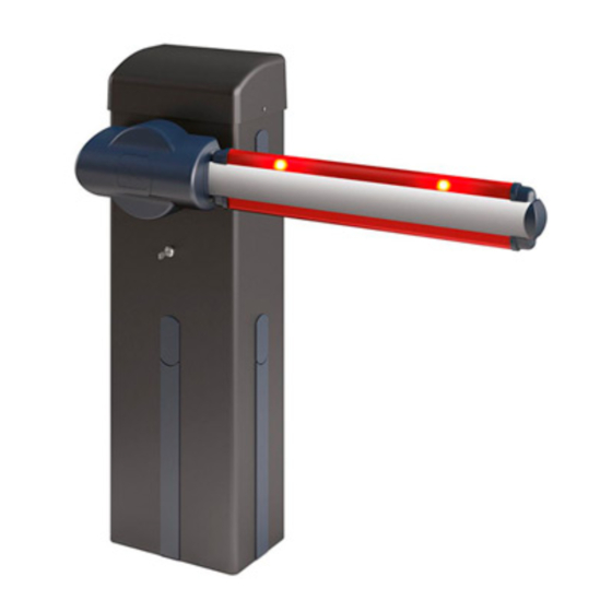
- Page 33 MANUALE PER L’INSTALLAZIONE Versioni trasmettitori utilizzabili: 2) GENERALITÀ Tutti i trasmettitori ROLLING CODE compatibili con: Barriera elettromeccanica compatta adatta a limitare aree private, parcheggi, accessi per uso esclusivamente veicolare. Disponibili per passaggi da 3 a 6 metri. Fi- 4.1) PIASTRA DI FONDAZIONE (Fig.B1) necorsa elettronici regolabili, garantiscono la corretta posizione d’arresto dell’asta.
- Page 34 MANUALE PER L’INSTALLAZIONE Morsetto Definizione Descrizione FASE Alimentazione monofase 220-230V ~ 50/60 Hz* NEUTRO JP31 PRIM TRASF Collegamento primario trasformatore, 220-230V ~. JP32 Alimentazione scheda: JP13 SEC TRASF 24V~ Secondario trasformatore MOT + Collegamento motore MOT - Uscita configurabile AUX 0 - Default LAMPEGGIANTE. AUX 0 - CONTATTO ALIMENTATO 2°CANALE RADIO/ SPIA CANCELLO APERTO SCA/ Comando LUCE CORTESIA/ Comando LUCE ZONA/ LUCE SCALE/ ALLARME 24V (N.O.) (1A MAX)
- Page 35 MANUALE PER L’INSTALLAZIONE Configurazione degli ingressi di sicurezza Logica SAFE= 0 - Ingresso configurato come Phot, fotocellula non verificata (*) (Fig.N, rif.1). Consente la connessione di dispositivi non dotati di contatto supplementare di verifica. In caso di oscuramento, le fotocellule sono attive sia in apertura che in chiusura. Un oscura- mento della fotocellula in chiusura, inverte il moto solo dopo il disimpegno della fotocellula.
- Page 36 MANUALE PER L’INSTALLAZIONE TABELLA “A” - MENU PARAMETRI - (PARA ) Parametro Min. Max. Default Personali Definizione Descrizione Tempo chiusura 0 Tempo di attesa prima della chiusura automatica. automatica [s] Tempo sgom- T. S GO 1 bero zona Tempo di sgombero della zona interessata dal traffico regolato dal semaforo.
- Page 37 MANUALE PER L’INSTALLAZIONE TABELLA “B” - LOGICHE - (LOGIC) Barrare Logica Definizione Default Opzioni settaggio eseguito Logica non attiva Tempo Chiusura Automatica Attiva la chiusura automatica Logica non attiva Chiusura rapida CH. R APIDA Chiude dopo 1 secondi dal disimpegno delle fotocellule prima di attendere il termine del TCA impostato Gli ingressi configurati come Start E, Start I, Ped funzionano con la logica 4 passi.
- Page 38 MASTER ante contrapposte in rete locale: la scheda è il master in una rete ad ante contrapposte senza di rete BFT.) modulo intelligente. (fig.L) Identifica l’indirizzo da 0 a 119 della scheda in una connessione di rete BFT locale. [ ___ ] Indirizzo ...
- Page 39 MANUALE PER L’INSTALLAZIONE Barrare Logica Definizione Default Opzioni settaggio eseguito Ingresso configurato come comando Start E. Ingresso configurato come comando Start I. Ingresso configurato come comando Open. Ingresso configurato come comando Close. Ingresso configurato come comando Ped. Ingresso configurato come comando Timer. Ingresso configurato come comando Timer Pedonale.
- Page 40 Closing photocell test failed software version ER04 logic setting stat vers bft . . . Safety edge test on slave motor failed (opposite leaves Check safety edge connection and/or parameter/ ER05 connection) logic settings Check safety edge connection and/or parameter/...
- Page 41 INSTALLATION MANUAL 5) FITTING OF THE ACTUATOR 2) GENERAL OUTLINE WARNING! The barrier must be exclusively used for vehicles to Compact electromechanical barrier suitable for limiting private areas, drive through. Pedestrians must not walk within the operator parkings, access areas for vehicles only. Available for passageways from 3 manoeuvring area.
-
Page 42: Maintenance
INSTALLATION MANUAL WARNING: The electrical connections must be carried out workmanlike by qualified experienced personnel, in conformity with all the current standards and with the use of appropriate materials. Lay out the electrical installation with reference to the current electrical standards. -
Page 43: Limit Switch Setting
INSTALLATION MANUAL aUX Logic= 5 - OPEN GATE ALARM output. The contact remains closed if the door stays open for longer than the “alarm time” parameter. O for Obstacle detected Aux logic= 6 - FLASHING LIGHT output. Contact stays closed while leaves are operating. Aux logic= 7 - SOLENOID LATCH output. - Page 44 INSTALLATION MANUAL 21) RESTORING FACTORY SETTINGS (Fig. 17.8) PASSWORD MENU (PASSWORD) WARNING: this operation will restore the control unit’s factory settings and all Used to set a password for the board’s wireless programming via the U-link network. transmitters stored in its memory will be deleted. With “PROTECTION LEVEL”...
- Page 45 INSTALLATION MANUAL Cross out Logic Definition Default setting Optional extras used Logic not enabled Fast closing FAST CLS. Closes 1 second after the photocells are cleared before waiting for the set TCA to elapse. Inputs configured as Start E, Start I, Ped step-by-step mov.
-
Page 46: Serial Mode
MASTER opposite leaves in local network: the control unit is the master in an opposite leaves network with no smart module (fig.L) Identifies board address from 0 to 119 in a local BFT net work connec tion. [ ___ ] Address ... - Page 47 INSTALLATION MANUAL Cross out Logic Definition Default setting Optional extras used Input configured as Start E command. Input configured as Start I command. Input configured as Open command. Input configured as Close command. Input configured as Timer command Input configured as Timer command. Input configured as Timer Pedestrian command Input configured as Phot (photocell) safety.
- Page 48 Essai photocellules ouverture échoué ER03 paramètres/logiques vérifier connexion photocellules et/ou configuration stat Essai photocellules fermeture échoué vers bft . . . ER04 paramètres/logiques Essai linteau sur moteur slave échoué (connexion vantaux Vérifiez connexion linteau et/ou configurations ER05 paramètres/logiques opposés) Vérifier connexion linteau et/ou configurations...
-
Page 49: Manuel D'installation
MANUEL D’INSTALLATION 2) GENERALITES Versions d’émetteurs utilisables : Barrière électromagnétique compacte adaptée pour limiter les zones privées, Tous les émetteurs ROLLING CODE compatibles: les parkings, les accès uniquement prévus pour les véhicules. Disponible pour des passages de 3 à 6 mètres. Les fins de course électroniques réglables garantissent la position correcte d’arrêt de la lisse. - Page 50 MANUEL D’INSTALLATION 13) BRANCHEMENT ELECTRIQUE (Fig. G) En amont de l’installation, il faut installer un disjoncteur avec distance Une fois que les câbles électriques adaptés ont été passés dans les gaines et d’ouverture des contacts égale ou supérieure à 3,5 mm, avec protection que les différents composants de l’automatisation ont été...
-
Page 51: Dispositifs De Sécurité
MANUEL D’INSTALLATION Logique Aux= 4 - Sortie LUMIÈRE ESCALIERS. Le contact reste fermé pendant 1 secondes après le début de la manœuvre. Logique Aux = 5 - Sortie ALARME PORTAIL OUVERT. Le contact reste fermé si le vantail reste ouvert pendant un laps de temps supérieur au paramètre « temps alarme ». O pour détection obstacle Logique Aux= 6 - Sortie pour CLIGNOTANT. - Page 52 MANUEL D’INSTALLATION • Clonage par substitution d’émetteurs déjà intégrés au récepteur 19) MODULES U-LINK EN OPTION • Gestion bases de données des émetteurs Consultez les instructions des modules U-link. • Gestion communauté de récepteurs Pour savoir comment utiliser ces fonctionnalités avancées consultez les instructions 19.1) BARRIÈRES OPPOSÉS (Fig.
- Page 53 MANUEL D’INSTALLATION TABLEAU “B” - LOGIQUES - (LOGIC) Cochez le Logique Définition Défaut réglage Options accompli Logique non active Temps fermeture automatique Active la fermeture automatique Logique non active Fermeture rapide FE. R AP Se ferme 1s après le dégagement des photocellules avant d’attendre la fin du TCA configuré. Les entrées configurées comme Start Mouvement pas à...
- Page 54 MAITRE vantaux coulissants opposés dans un réseau local : la carte est la maître dans un réseau à vantaux réseau BFT.) opposés sans module intelligent. (FIG. L) Identifie l'adresse de 0 à 119 d'une car te dans une connexion de réseau BFT locale. Adresse ...
- Page 55 MANUEL D’INSTALLATION Cochez le Logique Définition Défaut réglage Options accompli Entrée configurée comme commande Start E. Entrée configurée comme commande Start I. Entrée configurée comme commande Open. Entrée configurée comme commande Close. Entrée configurée comme commande Piéton. Entrée configurée comme commande Timer. Entrée configurée comme commande Timer Piéton.
- Page 56 Software-Versione Steuerung Test Leiste an Motor Slave fehlgeschlagen (Anschluss einander Den Anschluss der Leisten und/oder die Einstellung stat vers bft . . . ER05 entgegengesetzte Torflügel) der Parameter/Logiken überprüfen Den Anschluss der Leisten und/oder die Einstellung Test Leiste 8k2 fehlgeschlagen er06 der Parameter/Logiken überprüfen...
- Page 57 MONTAGEANLEITUNG 2) ALLGEMEINES Kontrollampe Tor offen: 24V~ 3W max Kompakte elektromechanische Schranke zum Absperren von Privatgrund- stücken, Parkplätzen oder Zufahrten. Erhältlich für Durchfahrtbreiten von 3 Blinkleuchte: 24V~ 25W max bis 6 Metern. Einstellbare elektronische Endlagenschalter garantieren dafür, Schmelzsicherungen: siehe Fig. G dass der Baum an der richtigen Stelle anhält.
- Page 58 MONTAGEANLEITUNG Antriebe. entsprechenden Anweisungshandbüchern vorgenommen. Schließen Sie die Schrankenbaum. Phase, den Nullleiter und die Erdung an (obligatorisch). Das Netzkabel wird Auflagegabel. mit der entsprechenden Kabelsperre blockiert, die Kabel der Zubehörvor- Sicherheitsleiste. richtungen in der Kabelsperre und der Schutzleiter (Erde) mit der gelb/grünen Ft,Fr) Lichtschrankenpaar.
- Page 59 MONTAGEANLEITUNG Logik Aux= 3 - Ausgang Befehl ZONENBELEUCHTUNG. Der Kontakt bleibt für die gesamte Dauer des Manövers aktiv. Logik Aux= 4 - Ausgang TREPPENBELEUCHTUNG. Der Kontakt bleibt bei Beginn des Manövers für 1 Sekunde geschlossen. Logik Aux = 5 - Ausgang ALARM TOR OFFEN. Der Kontakt bleibt geschlossen, falls der Torflügel für eine Zeit offen bleibt, die länger als der Parameter „Zeit Alarm“...
- Page 60 MONTAGEANLEITUNG “BLOC” angezeigt. Das Default-Password ist 1234 17.3) MENÜ LOGIKEN (LOGIC) (TABELLE “B” LOGIKEN) 18) ANSCHLUSS AN ERWEITERUNGSKARTEN UND HANDPROGRAMMIEREINHEIT 17.4) MENÜ FUNK (radio) (TABELLE “C” FUNK) VERSION > V1.40 (Fig. K) - WICHTIGER HINWEIS: KENNZEICHNEN SIE DEN ERSTEN Bitte nehmen Sie auf das entsprechende Handbuch Bezug. ABGESPEICHERTEN SENDER MIT DER SCHLÜSSEL-MARKE (MASTER).
- Page 61 MONTAGEANLEITUNG Parameter Min. Max. Default Persönlich Definition Beschreibung Betriebsgeschwindigkeit bei der Öffnung- offnungsge- Eingestellt wird der Schranke für die Geschwindigkeit: 1% ent- Geschwindigkeit spricht der Geschwindigkeit beim Soft-Stopp, 99% der Höchst- Öffnung schw geschwindigkeit. Betriebsgeschwindigkeit bei der Schließung- schliebge- Eingestellt wird der Schranke für die Geschwindigkeit: 1% ent- Geschwindigkeit spricht der Geschwindigkeit beim Soft-Stopp, 99% der Höchst- Schließung...
- Page 62 MONTAGEANLEITUNG vorgenommene Logik Definition Default Optionen Einstellung markieren Als Phot konfigurierter Eingang, Fotozelle. Als Phot test konfigurierter Eingang, überprüfte Fotozelle. Konfigurierung des Sicherheitseingangs Als Phot op konfigurierter Eingang, Fotozelle aktiv nur bei Öffnung. SAFE 1 SAFE 1. Als Phot op test konfigurierter Eingang, überprüfte Fotozelle aktiv nur bei Öffnung. ...
- Page 63 MASTER entgegengesetzte Tür in lokalem Netz: Die Karte ist der Master in einem Netz mit entgegenge- setzter Tür ohne intelligentes Modul. Fig. L) Identifiziert die Adresse von 0 bis 119 der Karte in einer lokalen BFT-Netzverbindung. [ ___ ] Adresse ADRESSE ...
- Page 64 MONTAGEANLEITUNG vorgenommene Logik Definition Default Optionen Einstellung markieren Als Befehl Start E konfigurierter Eingang. Als Befehl Start I konfigurierter Eingang. Als Befehl Open konfigurierter Eingang. Als Befehl Close konfigurierter Eingang. Als Befehl Ped konfigurierter Eingang. Konfigurierung des Eingangs EXPI2 der erweiterungskarte EXPI2 Als Befehl Timer konfigurierter Eingang.
- Page 65 Versión software central Comprobar conexión cantos y/o configuraciones Prueba canto 8k2 fallida stat vers bft . . . er06 parámetros/lógicas C o m p r o b a r c o n e x i o n e s m o t o r...
-
Page 66: Manual De Instalación
MANUAL DE INSTALACIÓN 2) GENERALIDADES Luz intermitente: 24V~ 25W max Barrera electromecánica compacta adecuada para limitar áreas privadas, aparcamientos y accesos para uso exclusivamente vehicular. Disponible Fusibles: Véase la Fig. G para aberturas de paso de 3 a 6 metros. La correcta posición de bloqueo Receptor de radio Rolling-Code del asta resulta garantizada por unos fines de carrera electromecánicos frecuencia 433.92MHz... - Page 67 MANUAL DE INSTALACIÓN Columna fotocélulas. de los accesorios en el prensacable, el conductor de protección (tierra) Transmisor 1-2-4 canales. con cubierta aislante de color amarillo/verde, se debe conectar en el RMM) Detector de presencia inductive borne específico. LOOP) Espiras detector de presencia. ATENCION: Las conexiones eléctricas deben ser realizadas por personal ADVERTENCIAS –...
-
Page 68: Dispositivos De Seguridad
MANUAL DE INSTALACIÓN Lógica Aux= 4 – Salida LUZ ESCALERAS. El contacto queda cerrado durante 1 segundo al comienzo de la maniobra. Lógica Aux = 5 – Salida ALARMA CANCELA ABIERTA. El contacto queda cerrado si la hoja queda abierta durante un tiempo doble respecto al parámetro “tiempo alarma”. O para detección del obstáculo. Lógica Aux= 6 –... - Page 69 MANUAL DE INSTALACIÓN programador portátil universal y la Guía general de programación de 19) MÓDULOS OPCIONALES U-LINK receptores. Consultar las instrucciones de los módulos U-link 17.5) MENÚ DE VALORES PREDETERMINADOS (default) (Fig. L) 19.1) CANCELAS CORREDERAS CONTRAPUESTAS Lleva nuevamente la central a los valores PREDETERMINADOS. Consultar las instrucciones del módulo U-link.
- Page 70 MANUAL DE INSTALACIÓN TABLA “B” - MENÚ LÓGICAS - (LOGIC) Marcar la Lógica Definición Default configuración Opciones realizada Lógica inactiva Tiempo de Cierre Automático Activa el cierre automático Lógica inactiva Cierre rápido CIERRE RAP Cierra tras 1 segundo de la desactivación de las fotocélulas antes de esperar que termine el TCA configurado. Las entradas configuradas como Start E, Start I, Ped funcionan con la lógica Movimiento paso a paso...
- Page 71 MASTER hojas contrapuestas en red local: la tarjeta es el master en una red de hojas contrapuestas sin módulo inteligente. (fig.L) BFT.) Identifica la dirección de 0 a119 de la tarjeta en una conexión de red BFT local. [ ___ ] Dirección ...
- Page 72 MANUAL DE INSTALACIÓN Marcar la Lógica Definición Default configuración Opciones realizada Entrada configurada como mando Start E. Entrada configurada como mando Start I. Entrada configurada como mando Open. Entrada configurada como mando Close. Entrada configurada como mando Peatonal. Entrada configurada como mando Timer. Entrada configurada como mando Timer Peatonal.
- Page 73 Test fotocellen opening mislukt ER03 parameters/logica's controleren Versie software centrale aansluiting fotocellen en/of instelling Test fotocellen sluiting mislukt stat vers bft . . . ER04 parameters/logica's controleren Test rand op slave-motor mislukt (verbinding tegenovergestelde Aansluiting randen en/of instellingen ER05 vleugels) parameters/logica’s controleren N°...
- Page 74 INSTALLATIEHANDLEIDING 2) ALGEMEEN Zwaailicht: 24V~ 25W max Compacte elektromechanische slagboom geschikt voor het afzetten van privégebieden, parkeerplaatsen, toegangen die alleen door voertuigen Zekeringen zie Fig. G gebruikt worden. Beschikbaar voor doorgangen van 3 tot 6 meter. Afstel- Aantal combinaties 4 miljard bare elektronische aanslagen garanderen de correcte stilstandspositie van Radio-ontvanger Rolling-Code geïn- de boom.
- Page 75 INSTALLATIEHANDLEIDING Zwaailicht. aansluiting volgens de aanwijzingen en de schema’s aanwezig in de desbe- Actuator. treffende instructiehandleidingen. De verbinding van de fase, de neutraal en Boom. de aarde uitvoeren (verplicht). De netwerkkabel moet geblokkeerd worden Steunvork. in de daarvoor bestemde kabelklem, de kabels van de accessoires in de Gevoelige rand.
- Page 76 INSTALLATIEHANDLEIDING Logica Aux= 10 – Uitgang ZWAAILICHT EN ONDERHOUD. Het contact blijft gesloten tijdens de beweging van de vleugels. Als bij gesloten hekvleugel de waarde wordt bereikt die in de parameter Onderhoud is ingesteld, zal het contact 4 maal 10s en 5s geopend worden om de aanvraag voor het onderhoud aan te duiden. niet beschikbaar Logica Aux= 11 - Logica Aux= 12 - uitgang status barrière: het contact blijft gesloten als de barrière volledig gesloten is.
- Page 77 INSTALLATIEHANDLEIDING 21) DE FABRIEKSINSTELLINGEN HERSTELLEN (Fig.M) 21) VERBINDING MET BEHEERSYSTEEM PARKEERPLAATSEN LET OP U herstelt de waarden die door de fabriek zijn ingesteld. De De kaart is voorzien van een uitgang voor de statuscontrole van de op dergelijke afstandsbedieningen in het geheugen worden gewist. wijze geconfigureerde barrière (Afb.G4).
- Page 78 INSTALLATIEHANDLEIDING Uitgevoerde Logica Definitie Default instelling Opties aanvinken De ingangen geconfigureerd als Start E, stap voor stap beweging Start I, Ped werken met de 4-staps logica. 2-STAPS 3-STAPS 4-STAPS De ingangen geconfigureerd als GESLOTEN OPENT Start E, Start I, Ped werken met de OPENT OPENT 3-staps logica.
- Page 79 MASTER tegenovergestelde vleugels in lokaal netwerk: de kaart is de master in een netwerk met tegen- netwerkaansluiting.) overgestelde vleugels zonder intelligente module. (fig.L) Om het adres van 0 tot 119 van de kaart in een lokale BFT-netwerkaansluiting te identificeren. [ ___ ] Adres ...
- Page 80 Uitgevoerde Logica Definitie Default instelling Opties aanvinken Ingang geconfigureerd als commando Start E. Ingang geconfigureerd als commando Start I. Ingang geconfigureerd als commando Open. Configuratie Ingang geconfigureerd als commando Close. van de ingang Ingang geconfigureerd als commando Voetgangers. EXPI2 in de uitbreidingskaart Ingang geconfigureerd als commando Timer.
Need help?
Do you have a question about the GIOTTO BT A 30-60S U and is the answer not in the manual?
Questions and answers