
Related Manuals for VIPA SLIO FM 050-1BB00


Summary of Contents for VIPA SLIO FM 050-1BB00
- Page 1 VIPA System SLIO FM | 050-1BB00 | Manual HB300E_FM | RE_050-1BB00 | Rev. 10/30 July 2010...
- Page 2 Copyright © VIPA GmbH. All Rights Reserved. This document contains proprietary information of VIPA and is not to be disclosed or used except in accordance with applicable agreements. This material is protected by the copyright laws. It may not be reproduced, distributed, or altered in any fashion by any entity (either internal or external to VIPA), except in accordance with applicable agreements, contracts or licensing, without the express written consent of VIPA and the business management owner of the material.
-
Page 3: Table Of Contents
Manual VIPA System SLIO Contents Contents About this manual ..................1 Safety information ..................2 Chapter 1 Basics and Assembly ............. 1-1 Safety Information for Users..............1-2 System conception ................1-3 Dimensions ..................1-6 Installation .................... 1-7 Wiring....................1-11 Trouble shooting - LEDs..............1-14 Installation guidelines ................. - Page 4 Manual VIPA System SLIO Contents HB300E - FM - RE_050-1BB00 - Rev. 10/30...
-
Page 5: About This Manual
Overview Chapter 1: Basics and Assembly The focus of this chapter is on the introduction of the VIPA System SLIO. Here you will find the information required to assemble and wire a controller system consisting of System SLIO components. Besides the dimensions the general technical data of System SLIO will be found. - Page 6 Manual VIPA System SLIO About this manual This manual describes the System SLIO function module 050-1BB00 from Objective and VIPA. contents It contains a description of the construction, project implementation and usage. The manual is targeted at users who have a background in automation Target audience technology.
-
Page 7: Safety Information
Manual VIPA System SLIO Safety information Safety information The System SLIO is constructed and produced for: Applications conforming with • communication and process control specifications • general control and automation applications • industrial applications • operation within the environmental conditions specified in the technical data •... - Page 8 Manual VIPA System SLIO Safety information HB300E - FM - RE_050-1BB00 - Rev. 10/30...
-
Page 9: Chapter 1 Basics And Assembly
Chapter 1 Basics and Assembly Chapter 1 Basics and Assembly The focus of this chapter is on the introduction of the VIPA System SLIO. Overview Here you will find the information required to assemble and wire a controller system consisting of System SLIO components. -
Page 10: Safety Information For Users
Manual VIPA System SLIO Chapter 1 Basics and Assembly Safety Information for Users VIPA modules make use of highly integrated components in MOS- Handling of Technology. These components are extremely sensitive to over-voltages electrostatic that can occur during electrostatic discharges. -
Page 11: System Conception
Manual VIPA System SLIO Chapter 1 Basics and Assembly System conception System SLIO is a modular automation system for assembly on a 35mm Overview mounting rail. By means of the peripheral modules with 2, 4 or 8 channels this system may properly be adapted matching to your automation tasks. - Page 12 Manual VIPA System SLIO Chapter 1 Basics and Assembly Each periphery module consists of a terminal and an electronic module. Periphery modules Terminal module Electronic module Terminal module The terminal module serves to carry the electronic module, contains the backplane bus with power supply for the electronic, the DC 24V power section supply and the staircase-shaped terminal for wiring.
- Page 13 Manual VIPA System SLIO Chapter 1 Basics and Assembly Accessories Shield bus carrier The shield bus carrier serves to carry the shield bus to connect cable shields. Shield bus carriers, shield bus and shield fixings are not in the scope of delivery. They are only available as accessories.
-
Page 14: Dimensions
Manual VIPA System SLIO Chapter 1 Basics and Assembly Dimensions Dimensions bus coupler 76.5 48.5 Dimensions periphery module 76.5 12.9 Dimensions electronic module 12.9 Dimensions in mm HB300E - FM - RE_050-1BB00 - Rev. 10/30... -
Page 15: Installation
Manual VIPA System SLIO Chapter 1 Basics and Assembly Installation Functional principle Mounting There is a locking lever at the top side of the terminal module. For terminal module mounting and de-mounting this locking lever is to turn upwards until this engages audible. - Page 16 Manual VIPA System SLIO Chapter 1 Basics and Assembly The modules were directly be mounted to the mounting rail and so Mounting connected to the backplane bus and the power supply for the electronic Proceeding and power section. Up to 64 modules may be mounted. Please consider here that the sum current of the electronic power supply does not exceed the maximum value of 3A.
- Page 17 Manual VIPA System SLIO Chapter 1 Basics and Assembly • Mounting Mount the periphery modules you want. periphery module Clack • After mounting the whole system, to protect the backplane bus Mounting the connectors the bus cover may now be mounted at the last module...
- Page 18 Manual VIPA System SLIO Chapter 1 Basics and Assembly With the mounting of a SLIO module respectively of a group of SLIO Mounting modules between two modules for mounting reasons you have always to between 2 remove the electronic module of the just mounted right module. After that it modules may be plugged again.
-
Page 19: Wiring
Manual VIPA System SLIO Chapter 1 Basics and Assembly Wiring Standard wiring SysDC5V max. 3A DC24V max. 10A DC24V DC24V [1] DC 24V Power section supply I/O area [2] DC 24V for Electronic power supply bus coupler and I/O area... - Page 20 If the 10A for the power section supply is no longer sufficient, you may use Deployment of the the power module from VIPA with the order number 007-1AB00. So you power modules have also the possibility to define isolated groups.
- Page 21 Manual VIPA System SLIO Chapter 1 Basics and Assembly To attach the shield the mounting of shield bus carriers are necessary. Shield attachment The shield bus carrier (available as accessory) serves to carry the shield bus to connect cable shields.
-
Page 22: Trouble Shooting - Leds
Manual VIPA System SLIO Chapter 1 Basics and Assembly Trouble shooting - LEDs Each module has the LEDs RUN and MF on its front side. Errors or General incorrect modules may be located by means of these LEDs. In the following illustrations flashing LEDs are marked by ☼. -
Page 23: Installation Guidelines
Manual VIPA System SLIO Chapter 1 Basics and Assembly Installation guidelines The installation guidelines contain information about the interference free General deployment of System SLIO. There is the description of the ways, interference may occur in your control, how you can make sure the electromagnetic digestibility (EMC), and how you manage the isolation. - Page 24 Manual VIPA System SLIO Chapter 1 Basics and Assembly In the most times it is enough to take care of some elementary rules to Basic rules for guarantee the EMC. Please regard the following basic rules when installing your PLC.
- Page 25 Manual VIPA System SLIO Chapter 1 Basics and Assembly Electrical, magnetically and electromagnetic interference fields are Isolation of weakened by means of an isolation, one talks of absorption. conductors Via the isolation rail, that is connected conductive with the rack, interference currents are shunt via cable isolation to the ground.
-
Page 26: General Data
Manual VIPA System SLIO Chapter 1 Basics and Assembly General data Conformity and approval Conformity 73/23/EWG Low-voltage directive Approval UL 508 Approval for USA and Canada others RoHs Product is unleaded Protection of persons and device protection Type of protection... - Page 27 Manual VIPA System SLIO Chapter 2 Hardware description Chapter 2 Hardware description In this chapter the counter module 050-1BB00 of the System SLIO is Overview described. Here every information about the hardware components of the module may be found. The technical data are at the end of the chapter.
-
Page 28: Chapter 2 Hardware Description
Manual VIPA System SLIO Chapter 2 Hardware description Properties • 2 counter 32bit (AB) invertible, DC 24V Features • Counting frequency max 400kHz (AB 1/2/4-fold evaluation or pulse and direction) • Comparison value, set value, input filter (configurable) • Interrupt and diagnostics function with µs time stamp •... -
Page 29: Structure
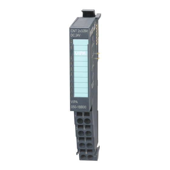
Manual VIPA System SLIO Chapter 2 Hardware description Structure Locking lever terminal module 050-1BB00 Labeling strip Backplane bus LED status indication DC 24V power section supply Electronic module Terminal module Locking lever electronic module Terminal Color Description Status indication green Bus communication is OK ●... - Page 30 Manual VIPA System SLIO Chapter 2 Hardware description For wires with a cross section of 0.08mm up to 1.5mm Pin assignment DC24V Pos. Function Type Description Counter 0: A / pulse Pulse input for counter signal respectively track A of an encoder for 1-, 2- or 4-fold evaluation.
- Page 31 Manual VIPA System SLIO Chapter 2 Hardware description Technical Data Order number 050-1BB00 Type FM 050 Module ID 08C3 380A Current consumption/power loss Current consumption from backplane bus 75mA Power loss 0.9W Technical data digital inputs Number of inputs Cable length, shielded...
- Page 32 Manual VIPA System SLIO Chapter 2 Hardware description Order number 050-1BB00 Status information, alarms, diagnostics Status display Interrupts yes, parameterizable Process alarm yes, parameterizable Diagnostic interrupt yes, parameterizable Diagnostic functions yes, parameterizable Diagnostics information read-out possible Module state green LED...
- Page 33 Manual VIPA System SLIO Chapter 3 Deployment Chapter 3 Deployment In this chapter the deployment of the System SLIO counter module Overview 050-1BB00 is described. Here every information required for the deployment may be found. Content Topic Page Chapter 3 Deployment ..............
- Page 34 Manual VIPA System SLIO Chapter 3 Deployment Fast introduction Limits Valid range of values Counter range Lower counter limit -2 147 483 648 (-2 Upper counter limit +2 147 483 647 (2 The maximum counter frequency is 400kHz. At CPU, Profibus and ProfiNET the input respectively output area is Address areas embedded to the corresponding address area.
- Page 35 Manual VIPA System SLIO Chapter 3 Deployment CTRL_I Name Function CTRL_II reserved Control word CTRL_COMP_SET enables the comparison bit SW_GATE_SET sets the software gate 3 ... 4 reserved COUNTERVAL_SET sets counter temporarily to the value of set value RES_SET resets the bits STS_CMP, STS_END,...
- Page 36 Manual VIPA System SLIO Chapter 3 Deployment The counter is controlled via the internal gate (I gate). The I gate Control counter corresponds to the software gate (SW gate). SW gate: Open (activate): in user program by edge 0-1 SW_GATE_SET in the control word.
- Page 37 Manual VIPA System SLIO Chapter 3 Deployment In-/Output area The following areas of the in-/output area are used by the 050-1BB00: Overview At CPU, Profibus and ProfiNET the input respectively output area is embedded to the corresponding address area. IX = Index for access via CANopen with s = subindex, depends on number...
- Page 38 Manual VIPA System SLIO Chapter 3 Deployment Addr. Name Bytes Function Output area CC_I Counter 0: Comp. value 5600h/s 12byte CC_II Counter 1: Comp. value 5600h/s+1 02h CCTRL_I Counter 0: Control word 5602h/s CCTRL_II Counter 1: Control word 5602h/s+1 04h...
- Page 39 Manual VIPA System SLIO Chapter 3 Deployment Parameter data Via parameterization you may define among others: Overview • Interrupt behavior • Input filter • Counter operating mode res. behavior DS = Data set for access via CPU, Profibus and ProfiNET...
- Page 40 Manual VIPA System SLIO Chapter 3 Deployment Byte Function Possible values CHxx Input frequency C0 track A Input frequency 02h: 100kHz 07h: 5kHz Input frequency C0 track B 03h: 60kHz 08h: 2kHz Input frequency C1 track A 04h: 30kHz 09h: 1kHz...
- Page 41 Manual VIPA System SLIO Chapter 3 Deployment Byte Bit 7 ... 0 MODE3_I/II C0/C1: Bit 2 ... 0: Signal evaluation 000b = Counter de-activated Counter mode 3 001b = Rotary encoder single (at A and B) 010b = Rotary encoder double (at A and B)
- Page 42 Manual VIPA System SLIO Chapter 3 Deployment Counter functions You may count forward and backwards and choose between the following Overview counter functions: • Count endless, e.g. distance measuring with incremental encoder • Count once, e.g. count to a maximum limit •...
- Page 43 Manual VIPA System SLIO Chapter 3 Deployment In this operating mode, the counter counts from the load value. Count continuously When the counter counts forward and reaches the upper count limit and another counting pulse in positive direction arrives, it jumps to the lower count limit and counts from there on.
- Page 44 Manual VIPA System SLIO Chapter 3 Deployment Count Once No main counting direction • The counter counts once starting with the load value. • You may count forward or backwards. • The count limits are set to the maximum count range.
- Page 45 Manual VIPA System SLIO Chapter 3 Deployment Main counting direction forward • The counter counts starting with the load value. • When the counter reaches the end value -1 in positive direction, it jumps to the load value at the next positive count pulse and the internal gate is automatically closed.
- Page 46 Manual VIPA System SLIO Chapter 3 Deployment Count Periodically No main counting direction • The counter counts forward or backwards starting with the load value. • At over- or under flow at the count limits, the counter jumps to the load value and counts from there on.
- Page 47 Manual VIPA System SLIO Chapter 3 Deployment Main counting direction backwards • The counter counts backwards starting with the load value. • When the counter reaches the end value +1 in negative direction, it jumps to the load value at the next negative count pulse. If enabled additionally a process interrupt is triggered.
- Page 48 Manual VIPA System SLIO Chapter 3 Deployment Counter additional functions The following additional functions may be set for each counter via the Overview parameterization: • Gate function The gate function serves for the start, stop and interrupt of a count function.
- Page 49 Manual VIPA System SLIO Chapter 3 Deployment The activation res. de-activation of the counter happens via an internal gate Gate function (I gate). The I gate corresponds to the software gate (SW gate). The SW gate is opened (activated) via your user application by an edge 0-1 of the bit SW_GATE_SET of the control word in the output area.
- Page 50 Manual VIPA System SLIO Chapter 3 Deployment The compare value is to be pre-defined by the output area. The comparison Comparison bit may be found at the counter status at STS_COMP. function Please consider that the bit STS_COMP may only be influenced when in the counter status the bit STS_CTRL_COMP is set.
- Page 51 Manual VIPA System SLIO Chapter 3 Deployment The hysteresis serves e.g. the avoidance of many toggle processes of the Hysteresis interrupt, if the counter value is in the range of the comparison value. You may set a range of 0 to 255. The settings 0 and 1 deactivate the hysteresis.
- Page 52 Manual VIPA System SLIO Chapter 3 Deployment Effect at counter value comparison value Counter value Hysteresis Comparison value Comparison bit: Hysteresis = 0 Hysteresis = 3 (1) Counter value = comparison value → comparison bit is set and hysteresis activated (2) Leave hysteresis range →...
- Page 53 Manual VIPA System SLIO Chapter 3 Deployment Diagnostic and interrupt Event Process Diagnostics parameterizable Overview interrupt interrupt Overflow Underflow Comparison value End value Process interrupt lost So you may react to asynchronous events, there is the possibility to Process interrupt activate a process interrupt.
- Page 54 Manual VIPA System SLIO Chapter 3 Deployment Via the parameterization you may activate a diagnostic interrupt for the Diagnostic data module. With a diagnostic interrupt the module serves for diagnostic data for diagnostic interrupt incoming As soon as the reason for releasing a diagnostic interrupt is no longer present, the diagnostic interrupt automatically takes place.
- Page 55 Manual VIPA System SLIO Chapter 3 Deployment ERR_D Byte Bit 7 ... 0 Diagnostic Bit 5 ... 0: reserved Bit 6: set at process interrupt lost Bit 7: reserved CHTYP Byte Bit 7 ... 0 Channel type Bit 6 ... 0: Channel type...
- Page 56 Manual VIPA System SLIO Chapter 3 Deployment 3-24 HB300E - FM - RE_050-1BB00 - Rev. 10/30...
Need help?
Do you have a question about the SLIO FM 050-1BB00 and is the answer not in the manual?
Questions and answers