Table of Contents
Advertisement
Advertisement
Table of Contents

Related Manuals for VIPA IM Series


Summary of Contents for VIPA IM Series
- Page 1 VIPA System 200V IM | Manual HB97E_IM | RE_253-xDPxx | Rev. 12/44 November 2012...
- Page 2 Copyright © VIPA GmbH. All Rights Reserved. This document contains proprietary information of VIPA and is not to be disclosed or used except in accordance with applicable agreements. This material is protected by the copyright laws. It may not be reproduced, distributed, or altered in any fashion by any entity (either internal or external to VIPA), except in accordance with applicable agreements, contracts or licensing, without the express written consent of VIPA and the business management owner of the material.
-
Page 3: Table Of Contents
Manual VIPA System 200V Contents Contents About this manual ..................1 Safety information ..................2 Chapter 1 Basics and Assembly ............. 1-1 Safety Information for Users..............1-2 System conception ................1-3 Dimensions ..................1-5 Installation .................... 1-7 Demounting and module exchange ............ 1-11 Wiring.................... - Page 4 Contents Manual VIPA System 200V HB97E - IM - RE_253-xDPxx - Rev. 12/44...
-
Page 5: About This Manual
Overview Chapter 1: Basics and Assembly The focus of this chapter is on the introduction of the VIPA System 200V. Here you will find the information required to assemble and wire a controller system consisting of System 200V components. Besides the dimensions the general technical data of System 200V will be found. - Page 6 Manual VIPA System 200V Objective and This manual describes the System 200V PROFIBUS DP slave modules IM 253-xDPxx from VIPA. It contains a description of the construction, contents project implementation and usage. This manual is part of the documentation package with order number...
-
Page 7: Safety Information
Safety information Safety information The IM 253DP is constructed and produced for: Applications conforming with • all VIPA System 200V components specifications • communication and process control • general control and automation applications • industrial applications • operation within the environmental conditions specified in the technical data •... - Page 8 Safety information Manual VIPA System 200V HB97E - IM - RE_253-xDPxx - Rev. 12/44...
-
Page 9: Chapter 1 Basics And Assembly
Chapter 1 Basics and Assembly Overview The focus of this chapter is on the introduction of the VIPA System 200V. Here you will find the information required to assemble and wire a controller system consisting of System 200V components. Besides the dimensions the general technical data of System 200V will be found. -
Page 10: Safety Information For Users
Chapter 1 Basics and Assembly Manual VIPA System 200V Safety Information for Users Handling of VIPA modules make use of highly integrated components in MOS- electrostatic Technology. These components are extremely sensitive to over-voltages sensitive modules that can occur during electrostatic discharges. -
Page 11: System Conception
Manual VIPA System 200V Chapter 1 Basics and Assembly System conception Overview The System 200V is a modular automation system for assembly on a 35mm profile rail. By means of the peripheral modules with 4, 8 and 16 channels this system may properly be adapted matching to your automation tasks. - Page 12 Chapter 1 Basics and Assembly Manual VIPA System 200V Power supplies With the System 200V the DC 24V power supply can take place either externally or via a particularly for this developed power PS 207/2 supply. The power supply may be mounted on the...
-
Page 13: Dimensions
Manual VIPA System 200V Chapter 1 Basics and Assembly Dimensions Dimensions 1tier width (HxWxD) in mm: 76 x 25.4 x 74 Basic enclosure 2tier width (HxWxD) in mm: 76 x 50.8 x 74 Installation dimensions Installed and wired dimensions In- / Output... - Page 14 Chapter 1 Basics and Assembly Manual VIPA System 200V Function modules/ 89 mm 88 mm Extension modules 85 mm 84,46 mm 11 mm 4,66 mm CPUs (here with 91 mm 89 mm EasyConn from 85 mm VIPA) 11 mm 5 mm...
-
Page 15: Installation
Bus connector System 200V modules communicate via a backplane bus connector. The backplane bus connector is isolated and available from VIPA in of 1-, 2-, 4- or 8tier width. The following figure shows a 1tier connector and a 4tier connector bus: The bus connector is to be placed on the profile rail until it clips in its place and the bus connections look out from the profile rail. - Page 16 • Sort the modules with a high current consumption right beside the head consumption module. In the service area of www.vipa.com a list of current consumption of every System 200V module can be found. HB97E - IM - RE_253-xDPxx - Rev. 12/44...
- Page 17 Manual VIPA System 200V Chapter 1 Basics and Assembly Assembly possibilities hoizontal assembly vertical Please regard the allowed environmental temperatures: assembly • horizontal assembly: from 0 to 60°C • vertical assembly: from 0 to 40°C • lying assembly: from 0 to 40°C...
- Page 18 Chapter 1 Basics and Assembly Manual VIPA System 200V Assembly procedure • Install the profile rail. Make sure that a clearance of at least 60mm exists above and 80mm below the middle of the profile rail. • Press the bus connector into the profile rail until it clips securely into place and the bus-connectors look out from the profile rail.
-
Page 19: Demounting And Module Exchange
Manual VIPA System 200V Chapter 1 Basics and Assembly Demounting and module exchange • Remove if exists the wiring to the module, by pressing both locking lever on the connector and pulling the connector. • The casing of the module has a spring loaded clip at the bottom by which the module can be removed. -
Page 20: Wiring
Chapter 1 Basics and Assembly Manual VIPA System 200V Wiring Overview Most peripheral modules are equipped with a 10pole or a 18pole connector. This connector provides the electrical interface for the signaling and supply lines of the modules. The modules carry spring-clip connectors for interconnections and wiring. - Page 21 Manual VIPA System 200V Chapter 1 Basics and Assembly Wiring procedure • Install the connector on the module until it locks with an audible click. For this purpose you press the two clips together as shown. The connector is now in a permanent position and can easily be wired.
-
Page 22: Installation Guidelines
Chapter 1 Basics and Assembly Manual VIPA System 200V Installation guidelines General The installation guidelines contain information about the interference free deployment of System 200V systems. There is the description of the ways, interference may occur in your control, how you can make sure the electromagnetic digestibility (EMC), and how you manage the isolation. - Page 23 Manual VIPA System 200V Chapter 1 Basics and Assembly Basic rules for In the most times it is enough to take care of some elementary rules to guarantee the EMC. Please regard the following basic rules when installing your PLC.
- Page 24 Chapter 1 Basics and Assembly Manual VIPA System 200V Isolation of Electrical, magnetically and electromagnetic interference fields are conductors weakened by means of an isolation, one talks of absorption. Via the isolation rail, that is connected conductive with the rack, interference currents are shunt via cable isolation to the ground.
-
Page 25: General Data
Manual VIPA System 200V Chapter 1 Basics and Assembly General data • Profile rail 35mm Structure/ • Peripheral modules with recessed labelling dimensions • Dimensions of the basic enclosure: 1tier width: (HxWxD) in mm: 76x25.4x74 in inches: 3x1x3 2tier width: (HxWxD) in mm: 76x50.8x74 in inches: 3x2x3 •... - Page 26 Chapter 1 Basics and Assembly Manual VIPA System 200V 1-18 HB97E - IM - RE_253-xDPxx - Rev. 12/44...
-
Page 27: Chapter 2 Hardware Description
Manual VIPA System 200V Chapter 2 Hardware description Chapter 2 Hardware description Overview Here the hardware components of the IM 253-xDPxx are described. The technical data are at the end of the chapter. Contents Topic Page Chapter 2 Hardware description............2-1 Properties..................... -
Page 28: Properties
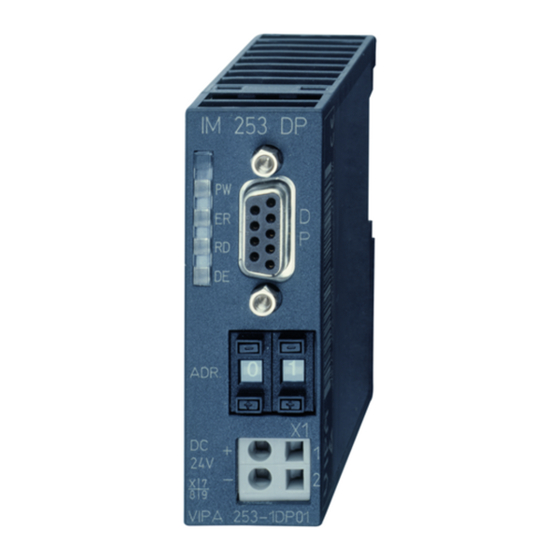
Chapter 2 Hardware description Manual VIPA System 200V Properties • Version with RS485 interface or fiber optic connectors PROFIBUS DP slaves • Version with DP-V1 interface • Online diagnostic protocol IM 253DP IM 253 DPO IM 253DP Adr. ADR. ADR. -
Page 29: Im 253-1Dp01 - Dp-V1 Slave - Structure
Manual VIPA System 200V Chapter 2 Hardware description IM 253-1DP01 - DP-V1 slave - Structure • PROFIBUS (DP-V0, DP-V1) Properties IM 253DP • PROFIBUS DP slave for max. 32 peripheral modules (max. 16 analog modules) • Max. 244Byte input data and 244Byte output data •... - Page 30 Chapter 2 Hardware description Manual VIPA System 200V RS485 interface A 9pin socket is provided for the RS485 interface between your PROFIBUS slave and the PROFIBUS. Power supply Every PROFIBUS slave has an internal power supply. This power supply requires DC 24V. In addition to the electronics on the bus coupler, the supply voltage is also used to power any modules connected to the backplane bus.
-
Page 31: Im 253-1Dp11 - Dp-V1 Slave - Structure
Manual VIPA System 200V Chapter 2 Hardware description IM 253-1DP11 - DP-V1 slave - Structure • PROFIBUS (DP-V0, DP-V1) Properties IM 253DPO • PROFIBUS DP slave for max. 32 peripheral modules (max. 16 analog modules) • Max. 244Byte input data and 244Byte output data •... - Page 32 Chapter 2 Hardware description Manual VIPA System 200V FO interface These connectors are provided for the fiber optic connectors between your PROFIBUS coupler and PROFIBUS. The diagram on the left shows the layout of the interface. Power supply Every PROFIBUS slave has an internal power supply. This power supply requires DC 24V.
-
Page 33: Im 253-1Dp31 - Dp-V1 Slave - Structure
Manual VIPA System 200V Chapter 2 Hardware description IM 253-1DP31 - DP-V1 slave - Structure • PROFIBUS (DP-V0, DP-V1) Properties IM 253DP • PROFIBUS DP slave for max. 8 peripheral modules (max. analog modules) • The PROFIBUS address can be adjusted by DIP switch •... - Page 34 Chapter 2 Hardware description Manual VIPA System 200V RS485 interface A 9pin socket is provided for the RS485 interface between your PROFIBUS slave and the PROFIBUS. Power supply Every PROFIBUS slave has an internal power supply. This power supply requires DC 24V. In addition to the electronics on the bus coupler, the supply voltage is also used to power any modules connected to the backplane bus.
-
Page 35: Im 253-2Dp50 - Dp-V0 Slave (Redundant) - Structure
Manual VIPA System 200V Chapter 2 Hardware description IM 253-2DP50 - DP-V0 slave (redundant) - Structure • 2 redundant channels Properties IM 253DPR • DPR slave for max. 32 peripheral modules (max. 16 analog modules) • Max. 152Byte input data and 152Byte output data •... - Page 36 Chapter 2 Hardware description Manual VIPA System 200V Power supply Every PROFIBUS slave has an internal power supply. This power supply requires DC 24V. In addition to the electronics on the bus coupler, the supply voltage is also used to power any modules connected to the backplane bus.
-
Page 37: Technical Data
Manual VIPA System 200V Chapter 2 Hardware description Technical data 253-1DP01 Order number 253-1DP01 Type IM 253DP, PROFIBUS-DP slave Technical data power supply Power supply (rated value) DC 24 V Power supply (permitted range) DC 20.4...28.8 V Reverse polarity protection... - Page 38 Chapter 2 Hardware description Manual VIPA System 200V 253-1DP11 Order number 253-1DP11 Type IM 253DPO, PROFIBUS-DP slave Technical data power supply Power supply (rated value) DC 24 V Power supply (permitted range) DC 20.4...28.8 V Reverse polarity protection Current consumption (no-load operation)
- Page 39 Manual VIPA System 200V Chapter 2 Hardware description 253-1DP31 Order number 253-1DP31 Type IM 253DP, PROFIBUS-DP slave Technical data power supply Power supply (rated value) DC 24 V Power supply (permitted range) DC 20.4...28.8 V Reverse polarity protection Current consumption (no-load operation)
- Page 40 Chapter 2 Hardware description Manual VIPA System 200V 253-2DP50 Order number 253-2DP50 Type IM 253DPR, PROFIBUS-DP slave Technical data power supply Power supply (rated value) DC 24 V Power supply (permitted range) DC 20.4...28.8 V Reverse polarity protection Current consumption (no-load operation)
-
Page 41: Chapter 3 Deployment Im 253Dp
253-xDPxx under PROFIBUS. A short introduction and presentation of the system is followed by the project design and configuration of the PROFIBUS slave modules that are available from VIPA. The chapter concludes with a number of communication examples and the technical data. -
Page 42: Basics Profibus
Chapter 3 Deployment IM 253DP Manual VIPA System 200V Basics PROFIBUS General PROFIBUS is an international standard applicable to an open fieldbus for building, manufacturing and process automation. PROFIBUS defines the technical and functional characteristics of a serial fieldbus system that can be used to create a low (sensor-/actuator level) or medium (process level) performance network of programmable logic controllers. - Page 43 Slave devices A PROFIBUS slave acquires data from peripheral equipment, sensors, actuators and transducers. The VIPA PROFIBUS couplers (IM 253DP, IM 253DPO and the CPU 24xDP, CPU 21xDP) are modular slave devices that transfer data between the System 200V periphery and the high-level master.
- Page 44 Where the data length exceeds a byte, for example in analog values, the data consistency must be extended. VIPA PROFIBUS DP master guarantees (from Firmware version V3.00) that the consistency will cater for the required length.
- Page 45 Manual VIPA System 200V Chapter 3 Deployment IM 253DP • Max. 125 DP slaves at one DP master - max. 32 slaves/segment Restrictions • Max. 16 DPO slaves at one DPO master at 1.5MBaud • You can only install or remove peripheral modules when you have turned the power off! •...
- Page 46 Manual VIPA System 200V V-bus cycle A V-bus cycle (V-Bus = VIPA backplane bus) saves all the input data from the modules in the PII and all the output data from the PIQ in the output modules. When the data has been saved the PII is transferred into the ”buffer send”...
- Page 47 Manual VIPA System 200V Chapter 3 Deployment IM 253DP The key feature of version DP-V1 is the extended function for acyclic data Function communication. This forms the requirement for parameterization and Acyclic data calibration of the field devices over the bus during runtime and for the communication introduction of confirmed alarm messages.
- Page 48 Chapter 3 Deployment IM 253DP Manual VIPA System 200V Services Additional available services are shown in following table. Acyclic data More detailed information to the services and the DP-V0/1 communication - communication principles is to find in the PROFIBUS norm IEC 61158.
- Page 49 Addressing must be an unique number in the bus system between 1 and 126. The address of the VIPA PROFIBUS coupler is set by the addressing switch located on the front of the module. You assign the address to the VIPA PROFIBUS master during the configuration phase.
-
Page 50: Im 253-2Dp50 - Dp-V0 Slave (Redundant System)
Chapter 3 Deployment IM 253DP Manual VIPA System 200V IM 253-2DP50 - DP-V0 slave (Redundant system) Redundant system In principal, the IM 253DPR consists of 2 PROFIBUS DP slave connections. The two PROFIBUS slaves are controlling the operating modes of each other. Both slaves have the same address at the PROFIBUS and are communicating with a redundant DP master. -
Page 51: Im 253-Xdpxx - Dp-V0 Slave - Project Engineering
The VIPA WinNCS configuration tool already contains all GSD-files for the VIPA components! You may also download the GSD file via the Service area www.vipa.com > Service > Downloads > PROFIBUS GSD files. After the installation of the GSD-file you will find this entry e.g. in the hardware catalog from Siemens at: PROFIBUS DP>Additional field devices>I/O>VIPA_System_200V>... - Page 52 Chapter 3 Deployment IM 253DP Manual VIPA System 200V After Power ON, the DP slave executes a self test. It controls its internal Start-up functions and the communication via the backplane bus. After the error free behavior IM start-up, the bus coupler switches into the state "ready". In this state, the...
-
Page 53: Im 253-Xdpxx - Dp-V0 Slave - Parameters
The following parameters are available: Slot number For reasons of compatibility to VIPA slaves with revision level 4 or lower, you may here select the start number of the slot numeration. With DP slaves rev. level 5 and higher, this parameter is ignored. -
Page 54: Im 253-Xdpxx - Dp-V0 Slave - Diagnostic Functions
The most recent 100 diagnostic messages along with a time stamp are stored in RAM res. saved to the Flash of every VIPA PROFIBUS slave. These can be analyzed by means of software. Please call the VIPA hotline for this purpose. - Page 55 Manual VIPA System 200V Chapter 3 Deployment IM 253DP The length of the diagnostic messages that are generated by the Structure of the PROFIBUS slave is 23Byte. This is also referred to as the device related DP-V0 diagnostic diagnostic data.
- Page 56 Chapter 3 Deployment IM 253DP Manual VIPA System 200V Header for This byte is only prepended to the device related diagnostic data when this device related is being transferred via PROFIBUS. diagnostic Byte Bit 7 ... Bit 0 Bit 0 ... Bit 5: Length device related diagnostic data incl. Byte 6 Bit 6 ...
- Page 57 Manual VIPA System 200V Chapter 3 Deployment IM 253DP The following section contains all the messages that the diagnostic data Overview of can consist of. The structure of Byte 2 ... Byte 23 depends on the message diagnostic (Byte 0). When the diagnostic data is transferred to the master via messages PROFIBUS, Byte 7 of the master corresponds to Byte 0 of the slave.
- Page 58 Chapter 3 Deployment IM 253DP Manual VIPA System 200V DP configurations error - entry Length: 6 Depending on the mode and when the length of the configuration message matches the length of the default configuration the different entries in the configuration message are compared to the default configuration.
- Page 59 Manual VIPA System 200V Chapter 3 Deployment IM 253DP V-bus delayed acknowledgment Length: 2 Reading or writing from/to digital modules failed Byte Bit 7 ... Bit 0 2Bh: V-bus delayed acknowledgment System 200V diagnostic alarm Length: 16 Byte Bit 7 ... Bit 0 32h: System 200V diagnostic alarm Module no.
- Page 60 X+6 Red_State of second slave X+7 00h: reserved, permanent 00h Include the As from GSD version 1.30 from VIPA, the virtual module "State byte IM253- redundancy state 2DP50" is available in the hardware catalog. When using this module into the during the project engineering.
-
Page 61: Im 253-Xdpx1 - Dp-V1 Slave - Project Engineering
The Slaves are projected via gsd-file at the hardware configuration. GSD- file Each PROFIBUS module is delivered with a floppy disk by vipa. The floppy disc contains all GSD- and type files of the PROFIBUS modules from VIPA as Cx000023_Vxxx.ZIP file. The assignment of the GSD-file to your slave is shown in the "Readme.txt"... - Page 62 Chapter 3 Deployment IM 253DP Manual VIPA System 200V After Power ON, the DP slave executes a self test. It controls its internal Start-up functions and the communication via the backplane bus. After the error free behavior IM start-up, the bus coupler switches into the state "ready". In this state, the...
-
Page 63: Im 253-Xdpx1 - Dp-V1 Slave - Parameters
Manual VIPA System 200V Chapter 3 Deployment IM 253DP IM 253-xDPx1 - DP-V1 slave - Parameters Outline At deployment of DP slaves presented in this manual there are parameters for configuration that are individually used for every slave. Parameters At usage of the corresponding GSD for DP-V0 operation you have the... - Page 64 Chapter 3 Deployment IM 253DP Manual VIPA System 200V DP-V1 At usage of a GSD for DP-V1 operation you have the following parameter UserPrmData data: Byte Bit 7 ... Bit 0 Default Bit 1 ... 0: 0 (fix) Bit 2: 0 = WD-Timebase 10ms 1 = WD-Timebase 1ms Bit 4 ...
- Page 65 Manual VIPA System 200V Chapter 3 Deployment IM 253DP When addressing data, PROFIBUS assumes that the physical structure of Addressing with the slaves is modular or it can be structured internally in logical functional Slot and Index units, so-called modules. This model is also used in the basic DP functions...
- Page 66 Chapter 3 Deployment IM 253DP Manual VIPA System 200V Data transmission Per default, one class-1 master and one class-2 master connection with 244Byte data (4Byte DP-V1 header plus 240Byte user data) are supported. The class-1 master connection is established together with the cyclic connection and is activated via the parameterization.
- Page 67 Manual VIPA System 200V Chapter 3 Deployment IM 253DP Module Via the index A3h, the module configuration of the modules at the configuration backplane bus can be monitored. Module type Identification No. of Digital No. of Digital (hex) Input-Byte Input-Byte...
-
Page 68: Im 253-Xdpx1 - Dp-V1 Slave - Diagnostic Functions
Additionally in the DP-V1 slave from VIPA the last 100 alarm messages are stored in a RAM res. in the flash with a time stamp and may be evaluated with a software. - Page 69 Manual VIPA System 200V Chapter 3 Deployment IM 253DP The diagnostic messages that are created by the PROFIBUS slave have, Structure of the depending on the parameterization, a length of 58Byte. DP-V1 diagnostic data via As soon as the PROFIBUS slave sends a diagnostic to the master, the PROFIBUS max.
- Page 70 Chapter 3 Deployment IM 253DP Manual VIPA System 200V Enhanced Via the Enhanced diagnostic, which can be activated by parameterization, diagnostic you gain information at which slot number (module) an error has occurred. More detailed information about the error is available via the Module state and the channel specific diagnostic.
- Page 71 Manual VIPA System 200V Chapter 3 Deployment IM 253DP Module state Via the Module state, which can be activated by parameterization, you gain information about the error that occurred at a module. Note! Note that the length of the Module state of the IM 253-1DP31 - ECO is limited to 6.
- Page 72 Chapter 3 Deployment IM 253DP Manual VIPA System 200V Channel specific With the channel specific diagnostic you gain detailed information about the Diagnostic channel error within a module. For the usage of the channel specific diagnostic you have to release the diagnostic alarm for every module via the parameterization.
- Page 73 Manual VIPA System 200V Chapter 3 Deployment IM 253DP The interrupts section of the slave diagnostic provides information on the Interrupts type of interrupt and the cause that triggered the input. The interrupt section has a maximum of 20bytes. A maximum of one interrupt can be used per slave diagnostic.
- Page 74 Chapter 3 Deployment IM 253DP Manual VIPA System 200V Alarm status at diagnostic alarm Bytes x+4 to x+7 (corresponds CPU diagnostic record set 0) Byte Bit 7 ... Bit 0 Bit 0: Module malfunction, i.e. a problem has been detected...
- Page 75 Manual VIPA System 200V Chapter 3 Deployment IM 253DP … Continue Alarm status at diagnostic alarm Bytes x+8 to x+19 (corresponds CPU diagnostic record set 1) Byte Bit 7 ... Bit 0 70h: Module with digital inputs 71h: Module with analog inputs...
-
Page 76: Im 253-Xdpx1 - Dp-V1 Slave - Firmware Update
IM 253-xDPx1 - DP-V1 slave - Firmware update Overview The firmware update for the DP-V1 slave VIPA 253-1DP01 is at this time only available with Siemens CPUs. For this your firmware is online transferred from the hardware configurator to the CPU, which passes the firmware on to the according DP slave via the connected DP master using PROFIBUS. -
Page 77: Im 253-Xdpx1 - Dp-V1 Slave - I&M Data
Preset Explanation Identification data 0: IM_INDEX: 65000 MANUFACTURER_ID read (2Byte) 22B hex Name of the manufacturer (555 dez) (555 dez = VIPA GmbH) ORDER_ID read (20Byte) depends on the Order number of the module module VIPA 253-1DP01/31 SERIAL_NUMBER read (16Byte) - Page 78 Chapter 3 Deployment IM 253DP Manual VIPA System 200V ... continue I&M data Access Preset Explanation SOFTWARE_REVISION read (4Byte) Firmware version Firmware version of the module. Vxyz An increase of the firmware version also increases the hardware revision REVISION_COUNTER read (2Byte)
-
Page 79: Profibus Installation Guidelines
Manual VIPA System 200V Chapter 3 Deployment IM 253DP PROFIBUS installation guidelines • A PROFIBUS DP network may only be built up in linear structure. PROFIBUS in general • PROFIBUS DP consists of minimum one segment with at least one master and one slave. - Page 80 Chapter 3 Deployment IM 253DP Manual VIPA System 200V • The bus must be terminated at both ends. Electrical system • Masters and slaves may be installed in any combination. • Any FO master may only be installed on an electrical system by means Combined system of an Optical Link Plug, i.e.
- Page 81 In PROFIBUS all participants are wired parallel. For that purpose, the bus bus connector cable must be feed-through. Via the order number VIPA 972-0DP10 you may order the bus connector "EasyConn". This is a bus connector with switchable terminating resistor and integrated bus diagnostic.
- Page 82 A (EN50170). Starting with release 5 you also can use highly flexible bus cable: Lapp Kabel order no.: 2170222, 2170822, 2170322. With the order no. 905-6AA00 VIPA offers the "EasyStrip" de-isolating tool that makes the connection of the EasyConn much easier.
- Page 83 • low weight and higher flexibility • corrosion resistant • safety from eavesdropping attempts FO cable VIPA recommends to use FO connector and cable supplied by Hewlett FO connector Packard (HP): HP order no.: FO cable HFBR-RUS500, HFBR-RUD500, HFBR-EUS500, HFBR-EUD500 HP order no.: FO connector...
- Page 84 Chapter 3 Deployment IM 253DP Manual VIPA System 200V Fiber optic cabling The VIPA fiber optic PROFIBUS coupler employs dual core plastic fiber under PROFIBUS optic cable as the communication medium. Please keep the following points in mind when you connect your PROFIBUS FO coupler: predecessor and successor must always be connected by means of a dual core FO cable.
- Page 85 Manual VIPA System 200V Chapter 3 Deployment IM 253DP FO connector without crimp-type assembly HP order no.: HFBR-4531 Advantages: no special tool required. Connection for predecessor This shell of this type of plug is provided with an integrated strain relief.
- Page 86 Chapter 3 Deployment IM 253DP Manual VIPA System 200V Example for a PROFIBUS network One CPU and The CPU should have a short cycle time to ensure that the data from slave multiple master no. 5 (on the right) is always up to date. This type of structure is only...
- Page 87 Manual VIPA System 200V Chapter 3 Deployment IM 253DP Multi master Multiple master connections on a single bus in conjunction with a number of system slaves: IM 208 IM 208 IM 253 IM 253 Input/output periphery Input/output periphery IM 253...
- Page 88 Chapter 3 Deployment IM 253DP Manual VIPA System 200V Optical PROFIBUS IM 208 1,2, IM 253 Input/output periphery IM 253 Input/output periphery IM 253 Input/output periphery IM 253 Input/output periphery Links to other masters via optical Expansion options - slaves optical...
- Page 89 Manual VIPA System 200V Chapter 3 Deployment IM 253DP Combination of In a combined fiber optical PROFIBUS system only one converter (OLP) optical and may be installed between any two masters! electrical PROFIBUS IM 208 IM 253 Input/output periphery Bus connector RS 485...
-
Page 90: Commissioning
A number of different transfer methods are employed due to the fact that a project number of different hardware versions of the VIPA PROFIBUS master modules are existing. These transfer methods are described in the master configuration guide for the respective hardware version. -
Page 91: Using The Diagnostic Leds
Manual VIPA System 200V Chapter 3 Deployment IM 253DP Using the diagnostic LEDs The following example shows the reaction of the LEDs for different types of network interruption. Master Interruption at position A The PROFIBUS has been interrupted. Interruption at position B Communication via the backplane bus has been interrupted. -
Page 92: Sample Projects For Profibus Communication
Chapter 3 Deployment IM 253DP Manual VIPA System 200V Sample projects for PROFIBUS communication Example 1 Problem The following example describes a communication between a master and a slave system. The master system consists of a CPU 21x (here CPU 214-1BA03) and a DP master IM 208DP. - Page 93 Manual VIPA System 200V Chapter 3 Deployment IM 253DP Engineering To be compatible with the Siemens SIMATIC Manager, you have to IM 208DP execute the following steps for the System 200V: • Start the Hardware configurator from Siemens • Install the GSD-file vipa_21x.gsd •...
- Page 94 • Connect your PU res. PC with your CPU via MPI. If your PU doesn't support MPI, you may use the VIPA "Green Cable" to establish a point-to-point connection. The "Green Cable" has the order number VIPA 950-0KB00 and may only be used with VIPA CPUs of the Systems 100V, 200V, 300V and 500V.
- Page 95 Manual VIPA System 200V Chapter 3 Deployment IM 253DP Example 2 Problem This example shows a communication between a CPU 21x (here CPU 214- 1BA03) with IM 208 DP master and a CPU 21xDP (here CPU 214-2BP03). Via this system, counter values should be exchanged via PROFIBUS and monitored at the output module of the respective partner.
- Page 96 Chapter 3 Deployment IM 253DP Manual VIPA System 200V Engineering To be compatible with the STEP 7 projecting tool from Siemens, you have CPU 214 of the to execute the following steps for CPU 214 and DP master: DP master •...
- Page 97 Manual VIPA System 200V Chapter 3 Deployment IM 253DP User application in The user application in the CPU 21x has 2 tasks to execute, shared the CPU 214 between two OBs: • Test the communication via control byte. Load the input byte from PROFIBUS and monitor the value at the output module.
- Page 98 Chapter 3 Deployment IM 253DP Manual VIPA System 200V Engineering To be compatible with the Siemens SIMATIC Manager, you have to CPU 214DP execute the following steps for the CPU 214DP: • Start the Hardware configurator from Siemens • Install the GSD-file vipa_21x.gsd •...
- Page 99 Manual VIPA System 200V Chapter 3 Deployment IM 253DP User application Like shown above, the user application has 2 tasks, shared between two in the CPU 214DP OBs: • Load the input byte from the PROFIBUS slave and monitor the value at the output module.
- Page 100 Chapter 3 Deployment IM 253DP Manual VIPA System 200V 3-60 HB97E - IM - RE_253-xDPxx - Rev. 12/44...
Need help?
Do you have a question about the IM Series and is the answer not in the manual?
Questions and answers