
Related Manuals for VIPA SLIO IM 053-1DN00


Summary of Contents for VIPA SLIO IM 053-1DN00
- Page 1 VIPA System SLIO IM | 053-1DN00 | Manual HB300E_IM | RE_053-1DN00 | Rev. 11/21 May 2011...
- Page 2 Copyright © VIPA GmbH. All Rights Reserved. This document contains proprietary information of VIPA and is not to be disclosed or used except in accordance with applicable agreements. This material is protected by the copyright laws. It may not be reproduced, distributed, or altered in any fashion by any entity (either internal or external to VIPA), except in accordance with applicable agreements, contracts or licensing, without the express written consent of VIPA and the business management owner of the material.
-
Page 3: Table Of Contents
Manual VIPA System SLIO Contents Contents About this manual ..................1 Safety information ..................2 Chapter 1 Basics and Assembly ............. 1-1 Safety Information for Users..............1-2 System conception ................1-3 Dimensions ..................1-6 Installation .................... 1-7 Wiring....................1-11 Trouble shooting - LEDs..............1-15 Installation guidelines ................. - Page 4 Contents Manual VIPA System SLIO HB300E - IM - RE_053-1DN00 - Rev. 11/21...
-
Page 5: About This Manual
Overview Chapter 1: Basics and Assembly The focus of this chapter is on the introduction of the VIPA System SLIO. Here you will find the information required to assemble and wire a controller system consisting of System SLIO components. Besides the dimensions the general technical data of System SLIO will be found. - Page 6 About this manual Manual VIPA System SLIO This manual describes the IM 053-1DN00 of the System SLIO from VIPA. Objective and It contains a description of the structure, project engineering and contents deployment. This manual is part of the documentation package...
-
Page 7: Safety Information
Manual VIPA System SLIO Safety information Safety information Applications The System SLIO is constructed and produced for: conforming with • communication and process control specifications • general control and automation applications • industrial applications • operation within the environmental conditions specified in the technical data •... - Page 8 Safety information Manual VIPA System SLIO HB300E - IM - RE_053-1DN00 - Rev. 11/21...
-
Page 9: Chapter 1 Basics And Assembly
Chapter 1 Basics and Assembly Overview The focus of this chapter is on the introduction of the VIPA System SLIO. Here you will find the information required to assemble and wire a controller system consisting of System SLIO components. Besides the dimensions the general technical data of System SLIO will be found. -
Page 10: Safety Information For Users
Chapter 1 Basics and Assembly Manual VIPA System SLIO Safety Information for Users Handling of VIPA modules make use of highly integrated components in MOS- Technology. These components are extremely sensitive to over-voltages electrostatic that can occur during electrostatic discharges. -
Page 11: System Conception
Manual VIPA System SLIO Chapter 1 Basics and Assembly System conception Overview System SLIO is a modular automation system for assembly on a 35mm mounting rail. By means of the peripheral modules with 2, 4 or 8 channels this system may properly be adapted matching to your automation tasks. - Page 12 Chapter 1 Basics and Assembly Manual VIPA System SLIO Each periphery module consists of a terminal and an electronic module. Periphery modules Terminal module Electronic module Terminal module The terminal module serves to carry the electronic module, contains the backplane bus with power supply for the electronic, the DC 24V power section supply and the staircase-shaped terminal for wiring.
- Page 13 Manual VIPA System SLIO Chapter 1 Basics and Assembly Accessories Shield bus carrier The shield bus carrier serves to carry the shield bus (10mm x 3mm) to connect cable shields. Shield bus carriers, shield bus and shield fixings are not in the scope of delivery.
-
Page 14: Dimensions
Chapter 1 Basics and Assembly Manual VIPA System SLIO Dimensions Dimensions bus coupler 76.5 48.5 Dimensions periphery module 76.5 12.9 Dimensions electronic module 12.9 Dimensions in mm HB300E - IM - RE_053-1DN00 - Rev. 11/21... -
Page 15: Installation
Manual VIPA System SLIO Chapter 1 Basics and Assembly Installation Functional principle Mounting There is a locking lever at the top side of the terminal module. For terminal module mounting and de-mounting this locking lever is to turn upwards until this engages audible. - Page 16 Chapter 1 Basics and Assembly Manual VIPA System SLIO The modules were directly be mounted to the mounting rail and so Mounting connected to the backplane bus and the power supply for the electronic Proceeding and power section. Up to 64 modules may be mounted. Please consider here that the sum current of the electronic power supply does not exceed the maximum value of 3A.
- Page 17 Manual VIPA System SLIO Chapter 1 Basics and Assembly • Mounting Mount the periphery modules you want. periphery module Clack • After mounting the whole system, to protect the backplane bus Mounting the bus cover connectors at the last module you have to mount the bus cover, now.
- Page 18 Chapter 1 Basics and Assembly Manual VIPA System SLIO With the mounting of a SLIO module respectively of a group of SLIO Mounting modules between two modules for mounting reasons you have always to between 2 remove the electronic module of the just mounted right module. After that it modules may be plugged again.
-
Page 19: Wiring
Manual VIPA System SLIO Chapter 1 Basics and Assembly Wiring Connectors Terminals with spring clamp technology are used for wiring. The spring clamp technology allows quick and easy connection of your signal and supply lines. In contrast to screw terminal connections this type of connection is vibration proof. - Page 20 Chapter 1 Basics and Assembly Manual VIPA System SLIO Standard wiring SysDC5V max. 3A DC24V max. 10A DC24V DC24V (1) DC 24V for power section supply I/O area (max 10A) (2) DC 24V for electronic power supply bus coupler and I/O area...
- Page 21 If the 10A for the power section supply is no longer sufficient, you may use Deployment of the the power module from VIPA with the order number 007-1AB00. So you power modules have also the possibility to define isolated groups.
- Page 22 Chapter 1 Basics and Assembly Manual VIPA System SLIO To attach the shield the mounting of shield bus carriers are necessary. Shield attachment The shield bus carrier (available as accessory) serves to carry the shield bus to connect cable shields.
-
Page 23: Trouble Shooting - Leds
Manual VIPA System SLIO Chapter 1 Basics and Assembly Trouble shooting - LEDs General Each module has the LEDs RUN and MF on its front side. Errors or incorrect modules may be located by means of these LEDs. In the following illustrations flashing LEDs are marked by ☼. -
Page 24: Installation Guidelines
Chapter 1 Basics and Assembly Manual VIPA System SLIO Installation guidelines General The installation guidelines contain information about the interference free deployment of System SLIO. There is the description of the ways, interference may occur in your control, how you can make sure the electromagnetic digestibility (EMC), and how you manage the isolation. - Page 25 Manual VIPA System SLIO Chapter 1 Basics and Assembly In the most times it is enough to take care of some elementary rules to Basic rules for guarantee the EMC. Please regard the following basic rules when installing your PLC.
- Page 26 Chapter 1 Basics and Assembly Manual VIPA System SLIO Electrical, magnetically and electromagnetic interference fields are Isolation of weakened by means of an isolation, one talks of absorption. conductors Via the isolation rail, that is connected conductive with the rack, interference currents are shunt via cable isolation to the ground.
-
Page 27: General Data
Manual VIPA System SLIO Chapter 1 Basics and Assembly General data Conformity and approval Conformity 2006/95/EG Low-voltage directive Approval UL 508 Approval for USA and Canada others RoHs Product is unleaded Protection of persons and device protection Type of protection... - Page 28 Chapter 1 Basics and Assembly Manual VIPA System SLIO 1-20 HB300E - IM - RE_053-1DN00 - Rev. 11/21...
- Page 29 Manual VIPA System SLIO Chapter 2 Hardware description Chapter 2 Hardware description Overview Here the hardware components of the IM 053-1DN00 are more described. You will find the technical data at the end of this chapter. Content Topic Page Chapter 2 Hardware description............
-
Page 30: Chapter 2 Hardware Description
Chapter 2 Hardware description Manual VIPA System SLIO Properties Features The interface module IM053-1DN00 is a head station for the SLIO peripheral system with an DeviceNet interface. Over the DeviceNet interface the input data can be read and output data written, which parameterization system, as well as updates be accomplished. -
Page 31: Structure
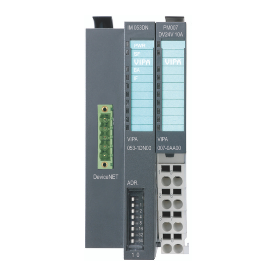
Manual VIPA System SLIO Chapter 2 Hardware description Structure 053-1DN00 Locking lever terminal module Labeling strip bus interface LED status indication bus interface Labeling strip power module LED status indication power module Backplane bus DC 24V power section supply Power module... - Page 32 Chapter 2 Hardware description Manual VIPA System SLIO Terminal For wires with a core cross-section of 0.08mm up to 1.5mm DC24V DC24V DC24V Pos. Function Type Description not connected DC 24V DC 24V for power section supply GND for power section supply...
- Page 33 Manual VIPA System SLIO Chapter 2 Hardware description Address switch The address switch serves for the following settings: • Transfer rate • DeviceNet address • Update mode for firmware update Note! Changes of the transfer rate respectively of the DeviceNet address were only recognized after PowerON or an automatic reset.
- Page 34 Chapter 2 Hardware description Manual VIPA System SLIO Technical Data Order number 053-1DN00 Type IM 053DN Module ID Technical data power supply Power supply (rated value) DC 24 V Power supply (permitted range) DC 20.4...28.8 V Reverse polarity protection Current consumption (no-load operation)
- Page 35 Manual VIPA System SLIO Chapter 3 Deployment Chapter 3 Deployment Overview This chapter describes the usage of the IM 053-1DN00 with DeviceNet. After a short introduction you may find here every information for the usage in the System SLIO. Content...
-
Page 36: Deployment
Chapter 3 Deployment Manual VIPA System SLIO Basics DeviceNet General DeviceNet is an open low-end network that is based upon the physical properties of CAN bus. The bus is also used to supply the devices with the required DC 24V power. - Page 37 ID address. Every DeviceNet device has addressing facilities. EDS file From VIPA there are EDS (Electronic Data Sheet) files for the DeviceNet coupler available. These files may either be found on the supplied storage media or at the download area of www.vipa.de.
-
Page 38: Accessing The System Slio
Chapter 3 Deployment Manual VIPA System SLIO Accessing the System SLIO Overview In the following you will find the description of accessing the following System SLIO areas via DeviceNet: • I/O area • Parameter data • Diagnostics data DeviceNet Device (Slave) - Page 39 (number of modules). These files may either be found on the supplied storage media or at the download area of www.vipa.de. Please install the required EDS file in your configuration tool. Details on the installation of the EDS file are available in the manual supplied with your configuration tool.
- Page 40 Chapter 3 Deployment Manual VIPA System SLIO The System SLIO modules may also be parameterized by the configuration Accessing the tool. parameter data For this your DeviceNet couple must be connected active at the bus. For parameterization and for the access to the diagnostics data the data type SHORT_STRING is used.
- Page 41 Manual VIPA System SLIO Chapter 3 Deployment The DeviceNet coupler only supports passive diagnostics. This means for Accessing the diagnostics that there is no alarm activation on module side necessary. diagnostics data You have to request the diagnosis. For this select in your configuration tool the corresponding DeviceNet-Slot.
-
Page 42: Transfer Rate And Devicenet Address
Chapter 3 Deployment Manual VIPA System SLIO Transfer rate and DeviceNet address Overview With PowerOFF there is the possibility to specify the Transfer rate respectively the DeviceNet-Address and then to activate these with PowerON. Note! Changes of the transfer rate respectively of the DeviceNet address were only recognized after PowerON or an automatic reset. - Page 43 Manual VIPA System SLIO Chapter 3 Deployment All stations on the bus must be uniquely identified by means of an Setting the ID address. DeviceNet The setting of the DeviceNet address happens with the following address proceeding: • Switch the power supply to PowerOFF.
-
Page 44: Status Indication - Diagnostics
- The module type of at least one module differs to the type of the configured module. Device error / internal error Please contact the VIPA support! on: ● off: ○ not relevant: X Blinking code B at a period duration of 1s: ○○●●...
Need help?
Do you have a question about the SLIO IM 053-1DN00 and is the answer not in the manual?
Questions and answers