
Related Manuals for VIPA 053-1EC00


Summary of Contents for VIPA 053-1EC00
- Page 1 VIPA System SLIO IM | 053-1EC00 | Manual HB300E_IM | RE_053-1EC00 | Rev. 11/03 January 2011...
- Page 2 Copyright © VIPA GmbH. All Rights Reserved. This document contains proprietary information of VIPA and is not to be disclosed or used except in accordance with applicable agreements. This material is protected by the copyright laws. It may not be reproduced, distributed, or altered in any fashion by any entity (either internal or external to VIPA), except in accordance with applicable agreements, contracts or licensing, without the express written consent of VIPA and the business management owner of the material.
-
Page 3: Table Of Contents
Manual VIPA System SLIO Contents Contents About this manual ..................1 Safety information ..................2 Chapter 1 Basics and Assembly ............. 1-1 Safety Information for Users..............1-2 System conception ................1-3 Dimensions ..................1-6 Installation .................... 1-7 Wiring....................1-11 Trouble shooting - LEDs..............1-14 Installation guidelines ................. -
Page 4: Hb300E - Im - Re_053-1Ec00 - Rev
Manual VIPA System SLIO Contents HB300E - IM - RE_053-1EC00 - Rev. 11/03... -
Page 5: About This Manual
Overview Chapter 1: Basics and Assembly The focus of this chapter is on the introduction of the VIPA System SLIO. Here you will find the information required to assemble and wire a controller system consisting of System SLIO components. Besides the dimensions the general technical data of System SLIO will be found. - Page 6 Manual VIPA System SLIO About this manual This manual describes the IM 053-1EC00 of the System SLIO from VIPA. It Objective and contains a description of the structure, project engineering and contents deployment. This manual is part of the documentation package...
-
Page 7: Safety Information
Manual VIPA System SLIO Safety information Safety information The System SLIO is constructed and produced for: Applications conforming with • communication and process control specifications • general control and automation applications • industrial applications • operation within the environmental conditions specified in the technical data •... - Page 8 Manual VIPA System SLIO Safety information HB300E - IM - RE_053-1EC00 - Rev. 11/03...
-
Page 9: Chapter 1 Basics And Assembly
Chapter 1 Basics and Assembly Chapter 1 Basics and Assembly The focus of this chapter is on the introduction of the VIPA System SLIO. Overview Here you will find the information required to assemble and wire a controller system consisting of System SLIO components. -
Page 10: Safety Information For Users
Manual VIPA System SLIO Chapter 1 Basics and Assembly Safety Information for Users VIPA modules make use of highly integrated components in MOS- Handling of Technology. These components are extremely sensitive to over-voltages electrostatic that can occur during electrostatic discharges. -
Page 11: System Conception
Manual VIPA System SLIO Chapter 1 Basics and Assembly System conception System SLIO is a modular automation system for assembly on a 35mm Overview mounting rail. By means of the peripheral modules with 2, 4 or 8 channels this system may properly be adapted matching to your automation tasks. - Page 12 Manual VIPA System SLIO Chapter 1 Basics and Assembly Each periphery module consists of a terminal and an electronic module. Periphery modules Terminal module Electronic module Terminal module The terminal module serves to carry the electronic module, contains the backplane bus with power supply for the electronic, the DC 24V power section supply and the staircase-shaped terminal for wiring.
- Page 13 Manual VIPA System SLIO Chapter 1 Basics and Assembly Accessories Shield bus carrier The shield bus carrier serves to carry the shield bus (10mm x 3mm) to connect cable shields. Shield bus carriers, shield bus and shield fixings are not in the scope of delivery.
-
Page 14: Dimensions
Manual VIPA System SLIO Chapter 1 Basics and Assembly Dimensions Dimensions bus coupler 76.5 48.5 Dimensions periphery module 76.5 12.9 Dimensions electronic module 12.9 Dimensions in mm HB300E - IM - RE_053-1EC00 - Rev. 11/03... -
Page 15: Installation
Manual VIPA System SLIO Chapter 1 Basics and Assembly Installation Functional principle Mounting There is a locking lever at the top side of the terminal module. For terminal module mounting and de-mounting this locking lever is to turn upwards until this engages audible. - Page 16 Manual VIPA System SLIO Chapter 1 Basics and Assembly The modules were directly be mounted to the mounting rail and so Mounting connected to the backplane bus and the power supply for the electronic Proceeding and power section. Up to 64 modules may be mounted. Please consider here that the sum current of the electronic power supply does not exceed the maximum value of 3A.
- Page 17 Manual VIPA System SLIO Chapter 1 Basics and Assembly • Mounting Mount the periphery modules you want. periphery module Clack • After mounting the whole system, to protect the backplane bus Mounting the connectors at the last module you have to mount the bus cover, now.
- Page 18 Manual VIPA System SLIO Chapter 1 Basics and Assembly With the mounting of a SLIO module respectively of a group of SLIO Mounting modules between two modules for mounting reasons you have always to between 2 remove the electronic module of the just mounted right module. After that it modules may be plugged again.
-
Page 19: Wiring
Manual VIPA System SLIO Chapter 1 Basics and Assembly Wiring Standard wiring SysDC5V max. 3A DC24V max. 10A DC24V DC24V (1) DC 24V for power section supply I/O area (max 10A) (2) DC 24V for electronic power supply bus coupler and I/O area... - Page 20 If the 10A for the power section supply is no longer sufficient, you may use Deployment of the the power module from VIPA with the order number 007-1AB00. So you power modules have also the possibility to define isolated groups.
- Page 21 Manual VIPA System SLIO Chapter 1 Basics and Assembly To attach the shield the mounting of shield bus carriers are necessary. Shield attachment The shield bus carrier (available as accessory) serves to carry the shield bus to connect cable shields.
-
Page 22: Trouble Shooting - Leds
Manual VIPA System SLIO Chapter 1 Basics and Assembly Trouble shooting - LEDs Each module has the LEDs RUN and MF on its front side. Errors or General incorrect modules may be located by means of these LEDs. In the following illustrations flashing LEDs are marked by ☼. -
Page 23: Installation Guidelines
Manual VIPA System SLIO Chapter 1 Basics and Assembly Installation guidelines The installation guidelines contain information about the interference free General deployment of System SLIO. There is the description of the ways, interference may occur in your control, how you can make sure the electromagnetic digestibility (EMC), and how you manage the isolation. - Page 24 Manual VIPA System SLIO Chapter 1 Basics and Assembly In the most times it is enough to take care of some elementary rules to Basic rules for guarantee the EMC. Please regard the following basic rules when installing your PLC.
- Page 25 Manual VIPA System SLIO Chapter 1 Basics and Assembly Electrical, magnetically and electromagnetic interference fields are Isolation of weakened by means of an isolation, one talks of absorption. conductors Via the isolation rail, that is connected conductive with the rack, interference currents are shunt via cable isolation to the ground.
-
Page 26: General Data
Manual VIPA System SLIO Chapter 1 Basics and Assembly General data Conformity and approval Conformity 2006/95/EG Low-voltage directive Approval UL 508 Approval for USA and Canada others RoHs Product is unleaded Protection of persons and device protection Type of protection... -
Page 27: Chapter 2 Hardware Description
Manual VIPA System SLIO Chapter 2 Hardware description Chapter 2 Hardware description Here the hardware components of the IM 053-1EC00 EtherCAT coupler Overview are more described. You will find the technical data at the end of this chapter. Content Topic... -
Page 28: Properties
Manual VIPA System SLIO Chapter 2 Hardware description Properties The EtherCAT coupler IM 053EC serves for an easy connection of Features decentralized periphery to EtherCAT. EtherCAT offers real time Ethernet technology on I/O level. • EtherCAT coupler for max. 64 peripheral modules •... -
Page 29: Structure
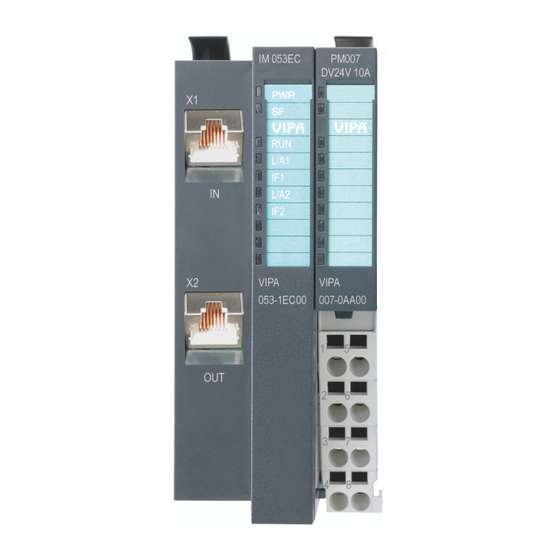
Manual VIPA System SLIO Chapter 2 Hardware description Structure Locking lever terminal module 053-1EC00 Labeling strip bus interface LED status indication bus interface Labeling strip power module LED status indication power module Backplane bus DC 24V power section supply Power module EtherCAT RJ45 bus interface "IN"... - Page 30 Manual VIPA System SLIO Chapter 2 Hardware description Status indication power module Color Description PWR IO green ● Power section supply OK PWR IO PF IO Fuse power section supply defective PF IO ● (Power fail) green ● Electronic section supply OK ●...
- Page 31 Manual VIPA System SLIO Chapter 2 Hardware description With the upper RJ45 "IN" jack the EtherCAT coupler is connected to the RJ45 EtherCAT EtherCAT network. To connect further EtherCAT slaves the RJ45 "OUT" bus interfaces jack below is used. Each jack has the following pin assignment:...
-
Page 32: Technical Data
Manual VIPA System SLIO Chapter 2 Hardware description Technical Data Order number 053-1EC00 Type IM 053EC Module ID Technical data power supply Power supply (rated value) DC 24 V Power supply (permitted range) DC 20.4...28.8 V Reverse polarity protection Current consumption (no-load operation) -
Page 33: Chapter 3 Deployment
Chapter 3 Deployment Chapter 3 Deployment This chapter describes the usage of the IM 053-1EC00 EtherCAT coupler Overview from VIPA. After a short introduction you may find here every information about assembly and project engineering. The chapter closes with the description of the error handling. -
Page 34: Basics
Manual VIPA System SLIO Chapter 3 Deployment Basics Field buses were established for many years in the automation technology. General Since higher speeds are required but the technical limits of this technology have already been reached, new solutions needed to be found. - Page 35 Manual VIPA System SLIO Chapter 3 Deployment At EtherCAT the master sends a telegram to the first station. The station Communication takes its data from the current data stream, inserts its answer data and principle sends the frame to the succeeding station. Here the frame is handled with the same way.
- Page 36 Status messages, which show the current state of the device, should directly be transferred within the process data. From VIPA there are ESI files for the EtherCAT coupler available. These ESI files files may either be found on the supplied storage media or at the download area of www.vipa.de.
-
Page 37: Ethercat State Machine
Manual VIPA System SLIO Chapter 3 Deployment EtherCAT State Machine Each EtherCAT couple has a State Machine implemented. For each state States there is defined which communication service is active via EtherCAT. The State Machine is controlled by the EtherCAT master. -
Page 38: Accessing The System Slio
Further within EtherCAT the slots are designated as EtherCAT-Slot. The counting always begins with 0. From VIPA you will get ESI files for the EtherCAT coupler. These files may ESI files either be found on the supplied storage media or at the download area of www.vipa.de. - Page 39 Manual VIPA System SLIO Chapter 3 Deployment By means of SDO access the in/output data of the object directory may be Access via SDO read. The following figure shows how the in/output data are mapped on the SDO objects: IM 053 EC...
- Page 40 Manual VIPA System SLIO Chapter 3 Deployment The following figure shows how the parameter data are mapped on the Accessing SDO objects: parameter data IM 053 EC SM 021 SM 022 SM 031 CM 001 FM 050 SM 021 DI 2x...
- Page 41 Manual VIPA System SLIO Chapter 3 Deployment Hardware and diagnostic interrupt data of System SLIO modules with Accessing interrupt capability were automatically sent by an emergency telegram if diagnostics data the interrupt is activated by parameterization. There is also the possibility to request diagnostics data via SDO.
- Page 42 Manual VIPA System SLIO Chapter 3 Deployment If the Alarm Status indicates a diagnostic interrupt the current diagnostics Diagnostic data data may be accessed via index 0x5002. The allocation of the diagnostics (Byte 1 ... 4) data may be found in the description of the corresponding module.
-
Page 43: Data Transfer Via Pdo And Sdo
Manual VIPA System SLIO Chapter 3 Deployment Data transfer via PDO and SDO Overview Objects Process data object Service data object Process data Mailbox EtherCAT PDO means Process Data Object. Process data may be transferred during run-time by means of PDOs. Here the Inputs respectively outputs are directly addressed within the frame. -
Page 44: Object Dictionary
Manual VIPA System SLIO Chapter 3 Deployment Object Dictionary Index Object Dictionary Area Object overview 0x0000 ... 0x0FFF Data Type Area 0x1000 ... 0x1FFF Communication Area 0x2000 ... 0x5FFF Manufacturer Specific Area 0x6000 ... 0x6FFF Input Area 0x7000 ... 0x7FFF Output Area 0x8000 ... - Page 45 Manual VIPA System SLIO Chapter 3 Deployment Device Type Index Sub- Name Type Attr. Default value Meaning index 0x1000 0x00 Device Type Unsigned32 0x00001389 0x00001389 means MDP Device Name Index Sub- Name Type Attr. Default value Meaning index 0x1008 0x00...
- Page 46 Manual VIPA System SLIO Chapter 3 Deployment Output Mapping Modules Index Sub- Name Type Attr. Default value Meaning index 0x1600 0x00 RxPDO Map Unsigned8 Number of Only available at slots with output outputs on modules. 0x163F this slot 0x01 Output Unsigned32 e.g.: 0x7000:01, 1 >...
- Page 47 Manual VIPA System SLIO Chapter 3 Deployment Sync Manager Type Index Sub- Name Type Attr. Default value Meaning index 0x1C00 0x00 Sync Manager Unsigned8 Type 0x01 Subindex 01 Unsigned8 0x02 Subindex 02 Unsigned8 0x03 Subindex 03 Unsigned8 0x04 Subindex 04...
- Page 48 Manual VIPA System SLIO Chapter 3 Deployment SM Output Parameter Index Sub- Name Type Attr. Default value Meaning index 0x1C32 0x00 SM output Unsigned8 parameter 0x01 Sync mode Unsigned16 0x02 Cycle time Unsigned32 0x03 Shift time Unsigned32 0x04 Sync modes...
- Page 49 Manual VIPA System SLIO Chapter 3 Deployment Here the EtherCAT coupler may be parameterized. Parameter SLIO EtherCAT Coupler Index Sub- Name Type Attr. Default value Meaning index 0x3000 0x00 Coupler Unsigned8 parameter 0x01 Auto- Unsigned8 Defines the mode, how interrupts Acknowledge are handled.
- Page 50 Manual VIPA System SLIO Chapter 3 Deployment Clear SLIO Counter Index Sub- Name Type Attr. Default value Meaning index 0x4000 0x00 Clear Slio Counter Unsigned8 Writing of a value you want to the corresponding index clears the counter 0x01 Clear Master Counter...
- Page 51 Manual VIPA System SLIO Chapter 3 Deployment Here the value of the versions of the components of the EtherCAT coupler Version may be accessed. Components EtherCAT Coupler Index Sub- Name Type Attr. Default value Meaning index 0x4100 0x00 SLIO Version...
- Page 52 Manual VIPA System SLIO Chapter 3 Deployment If the object 0xF100 (see below) indicates a hardware interrupt here the Hardware current hardware interrupt data may be accessed. The allocation of the Interrupt Data hardware interrupt data may be found in the description of the corresponding module.
- Page 53 Manual VIPA System SLIO Chapter 3 Deployment The whole diagnostic data of a module may be accessed with this object. Diagnostic Data Here you may either access current diagnostic data or the diagnostic data (Byte 1 ... n) of a module on any EtherCAT-Slot.
- Page 54 Manual VIPA System SLIO Chapter 3 Deployment With this object the input data of a System SLIO module may be read. Read Input Data Here the addressing of the EtherCAT-Slot via index (0x6000 + EtherCAT- Slot) takes place. The corresponding input data may be accessed via subindexes.
- Page 55 Manual VIPA System SLIO Chapter 3 Deployment Modular Device Profile Index Sub- Name Type Attr. Default value Meaning index 0xF000 0x00 Modular Unsigned8 Device Profile 0x01 Module Index Unsigned16 Distance 0x02 Maximum Unsigned16 0x40 (64) Number of Modules 0x03 Standard...
- Page 56 Manual VIPA System SLIO Chapter 3 Deployment Detected Address List Index Sub- Name Type Attr. Default value Meaning index 0xF040 0x00 Detected Unsigned8 Addresses of the modules, Address List which were recognized by the coupler 0x01 Subindex 001 Unsigned16 0x02...
-
Page 57: Error Handling
EEC - Emergency Emergency Error Codes following ETG specifications: error code 0xFFxx: Vendor-specific emergency message (VIPA = 0xFF00) 0xA0xx: State Machine transition error, e.g. due to a configuration error (length, address, settings). More information concerning this may be found at ETG. - Page 58 Manual VIPA System SLIO Chapter 3 Deployment Standard error messages are released within device-internal mechanisms Standard error and sent to the master. The following standard error messages my occur: messages To get more information about the error the EtherCAT master reads the AL AL Status Code Status Code (AL = application layer).
- Page 59 Manual VIPA System SLIO Chapter 3 Deployment SyncManager If there is no communication to the master possible e.g. line is interrupted, watchdog 0x001B you will get the error message 0x001B after the SyncMaster watchdog time has been elapsed. The time is to be configured in the master.
- Page 60 Manual VIPA System SLIO Chapter 3 Deployment 3-28 HB300E - IM - RE_053-1EC00 - Rev. 11/03...
Need help?
Do you have a question about the 053-1EC00 and is the answer not in the manual?
Questions and answers