
Related Manuals for VIPA CPU 013C


Summary of Contents for VIPA CPU 013C
- Page 1 VIPA System SLIO CPU | 013-CCF0R00 | Manual HB300 | CPU | 013-CCF0R00 | en | 17-20 SPEED7 CPU 013C www.vipa.com/en/service-support/manual...
- Page 2 VIPA GmbH Ohmstr. 4 91074 Herzogenaurach Telephone: 09132-744-0 Fax: 09132-744-1864 Email: info@vipa.com Internet: www.vipa.com 013-CCF0R0_000_CPU 013C,3,EN - © 2017...
-
Page 3: Table Of Contents
VIPA System SLIO Table of contents Table of contents General........................7 1.1 Copyright © VIPA GmbH ................. 7 1.2 About this manual..................... 8 1.3 Safety information..................... 9 Basics and mounting................... 10 2.1 Safety information for users................10 2.2 System conception..................11 2.2.1 Overview...................... - Page 4 VIPA System SLIO Table of contents 4.7.2 Parameter CPU................... 70 4.7.3 Parameter for MPI/DP ................73 4.8 Setting VIPA specific CPU parameters............74 4.9 Project transfer....................76 4.9.1 Transfer via MPI..................76 4.9.2 Transfer via Ethernet................... 77 4.9.3 Transfer via memory card................77 4.10 Accessing the web server................
- Page 5 VIPA System SLIO Table of contents 5.6.5 Counter operating modes................112 5.6.6 Counter - Additional functions..............119 5.6.7 Diagnostics and interrupt................125 5.7 Frequency measurement................125 5.7.1 Properties....................125 5.7.2 Wiring......................126 5.7.3 Proceeding....................127 5.7.4 Parametrization..................127 5.7.5 Status indication..................129 5.8 Pulse width modulation - PWM..............
- Page 6 10.1.2 Work environment of the TIA Portal............210 10.2 TIA Portal - Hardware configuration - CPU..........211 10.3 TIA Portal - Hardware configuration - Ethernet PG/OP channel....214 10.4 TIA Portal - VIPA-Include library..............217 10.5 TIA Portal - Project transfer................ 218 10.5.1 Transfer via MPI..................218 10.5.2 Transfer via Ethernet................
-
Page 7: General
This material is protected by the copyright laws. It may not be reproduced, distributed, or altered in any fashion by any entity (either internal or external to VIPA), except in accord- ance with applicable agreements, contracts or licensing, without the express written con- sent of VIPA and the business management owner of the material. -
Page 8: About This Manual
Tel.: +49 9132 744-1150 (Hotline) EMail: support@vipa.de 1.2 About this manual Objective and contents This manual describes the CPU 013-CCF0R00 of the System SLIO from VIPA. It contains a description of the construction, project implementation and usage. Product Order number... -
Page 9: Safety Information
VIPA System SLIO General Safety information Supplementary information and useful tips. 1.3 Safety information Applications conforming The system is constructed and produced for: with specifications communication and process control general control and automation tasks industrial applications operation within the environmental conditions specified in the technical data... -
Page 10: Basics And Mounting
Basics and mounting 2.1 Safety information for users Handling of electrostatic VIPA modules make use of highly integrated components in MOS-Technology. These sensitive modules components are extremely sensitive to over-voltages that can occur during electrostatic discharges. The following symbol is attached to modules that can be destroyed by elec- trostatic discharges. -
Page 11: System Conception
VIPA System SLIO Basics and mounting System conception > Overview 2.2 System conception 2.2.1 Overview System SLIO is a modular automation system for assembly on a 35mm mounting rail. By means of the peripheral modules with 2, 4 or 8 channels this system may properly be adapted matching to your automation tasks. -
Page 12: Components
Line extension Periphery modules Accessories CAUTION! Only modules of VIPA may be combined. A mixed operation with third- party modules is not allowed! CPU 01xC With this CPU 01xC, the CPU electronic, input/output components and power supply are integrated to one casing. In addition, up to 64 periphery modules of the System SLIO can be connected to the backplane bus. - Page 13 VIPA System SLIO Basics and mounting System conception > Components CAUTION! Bus interface and power module may not be separated! Here you may only exchange the electronic module! Line extension In the System SLIO there is the possibility to place up to 64 modules in on line. By means of the line extension you can divide this line into several lines.
-
Page 14: Accessories
There is the possibility to fix the assignment of electronic and terminal module. Here coding pins (order number 000-0AC00) from VIPA can be used. The coding pin consists of a coding jack and a coding plug. By combining electronic and terminal module with coding pin, the coding jack remains in the electronic module and the coding plug in the terminal module. -
Page 15: Dimensions
VIPA System SLIO Basics and mounting Dimensions 2.3 Dimensions Dimensions CPU 01xC Dimensions CPU 01x HB300 | CPU | 013-CCF0R00 | en | 17-20... - Page 16 VIPA System SLIO Basics and mounting Dimensions Dimensions bus coupler and line extension slave Dimensions line extension master HB300 | CPU | 013-CCF0R00 | en | 17-20...
- Page 17 VIPA System SLIO Basics and mounting Dimensions Dimension periphery module Dimensions electronic module Dimensions in mm HB300 | CPU | 013-CCF0R00 | en | 17-20...
-
Page 18: Mounting
VIPA System SLIO Basics and mounting Mounting > Mounting CPU 01xC 2.4 Mounting 2.4.1 Mounting CPU 01xC There are locking lever at the top side of the CPU. For mounting and demounting these locking lever are to be turned upwards until these engage. Place the CPU at the mounting rail. - Page 19 VIPA System SLIO Basics and mounting Mounting > Mounting CPU 01xC Turn the locking lever upwards, place the CPU at the mounting rail and turn the lever downward. ð If you want to use the CPU without periphery modules, the mounting is now complete.
-
Page 20: Wiring
VIPA System SLIO Basics and mounting Wiring > Wiring CPU 01xC After mounting the whole system, to protect the backplane bus connectors at the last module you have to mount the bus cover, now. If the last module is a clamp module, for adaptation the upper part of the bus cover is to be removed. - Page 21 VIPA System SLIO Basics and mounting Wiring > Wiring CPU 01xC Insert wire The wiring happens without a tool. Determine according to the casing labelling the connection position and insert through the round connection hole of the according contact your prepared wire until it stops, so that it is fixed.
- Page 22 VIPA System SLIO Basics and mounting Wiring > Wiring CPU 01xC Standard wiring (1) DC 24V for electronic section supply of the CPU, the internal I/Os and SLIO bus (2) DC 24V for power section supply integrated I/Os (3) DC 24V for power section supply SLIO bus The electronic power section supply is internally protected against higher voltage by fuse.
-
Page 23: Wiring Periphery Modules
VIPA System SLIO Basics and mounting Wiring > Wiring periphery modules To attach the shield the mounting of shield bus carriers are necessary. The shield bus carrier (available as accessory) serves to carry the shield bus to connect cable shields. - Page 24 VIPA System SLIO Basics and mounting Wiring > Wiring periphery modules Insert a suited screwdriver at an angel into the square opening as shown. Press and hold the screwdriver in the opposite direction to open the contact spring. Insert the stripped end of wire into the round opening. You can use wires with a cross section of 0.08mm...
-
Page 25: Wiring Power Modules
VIPA System SLIO Basics and mounting Wiring > Wiring power modules 2.5.3 Wiring power modules Terminal module terminals Power modules are either integrated to the head module or may be installed between the periphery modules. With power modules, terminals with spring clamp technology are used for wiring. - Page 26 VIPA System SLIO Basics and mounting Wiring > Wiring power modules Standard wiring (1) DC 24V for power section supply I/O area (max. 10A) (2) DC 24V for electronic power supply bus coupler and I/O area PM - Power module For wires with a core cross-section of 0.08mm...
- Page 27 If the 10A for the power section supply is no longer sufficient, you may use the power modules module from VIPA with the order number 007-1AB00. So you have also the possibility to define isolated groups. The power module with the order number 007-1AB10 is to be used if the 3A for the electronic power supply at the backplane bus is no longer sufficient.
- Page 28 VIPA System SLIO Basics and mounting Wiring > Wiring power modules Power module 007-1AB10 (1) DC 24V for power section supply I/O area (max. 10A) (2) DC 24V for electronic power supply bus coupler and I/O area (3) DC 24V for power section supply I/O area (max. 4A)
- Page 29 VIPA System SLIO Basics and mounting Wiring > Wiring power modules Attach the cables with the accordingly stripped cable screen and fix it by the shield clamp with the shield bus. HB300 | CPU | 013-CCF0R00 | en | 17-20...
-
Page 30: Demounting
VIPA System SLIO Basics and mounting Demounting > Demounting CPU 01xC 2.6 Demounting 2.6.1 Demounting CPU 01xC Proceeding Remove connector By means of a screwdriver there is the possibility to remove the connectors e.g. for module exchange with a fix wiring. For this each connector has a release lever centrally on its top side. - Page 31 VIPA System SLIO Basics and mounting Demounting > Demounting CPU 01xC To mount the CPU put it to the periphery module and push it, guided by the stripes, to the mounting rail. Turn all the locking lever downward, again. Plug again the electronic module, which you have removed before. For installation plug the electronic module guided by the strips at the lower side until this engages to the terminal module.
-
Page 32: Demounting Periphery Modules
VIPA System SLIO Basics and mounting Demounting > Demounting periphery modules 2.6.2 Demounting periphery modules Proceeding Exchange of an electronic Power-off your system. module For the exchange of a electronic module, the electronic module may be pulled for- ward after pressing the unlocking lever at the lower side of the module. - Page 33 VIPA System SLIO Basics and mounting Demounting > Demounting periphery modules Pull the module. For mounting turn the locking lever of the module to be mounted upwards. To mount the module put it to the gap between the both modules and push it, guided by the stripes at both sides, to the mounting rail.
-
Page 34: Trouble Shooting - Leds
VIPA System SLIO Basics and mounting Trouble shooting - LEDs Pull the module group forward. For mounting turn all the locking lever of the module group to be mounted upwards. To mount the module group put it to the gap between the both modules and push it, guided by the stripes at both sides, to the mounting rail. - Page 35 VIPA System SLIO Basics and mounting Trouble shooting - LEDs Reason: At this position a module is placed, which does not correspond to the configured module. Remedy: Match configuration and hardware structure. Module failure Behaviour: After PowerON all of the RUN LEDs up to the defective module are flashing.
-
Page 36: Installation Guidelines
The components of VIPA are developed for the deployment in industrial environments and meets high demands on the EMC. Nevertheless you should project an EMC planning before installing the components and take conceivable interference causes into account. - Page 37 VIPA System SLIO Basics and mounting Installation guidelines Proof the correct fixing of the lead isolation. – Data lines must be laid isolated. – Analog lines must be laid isolated. When transmitting signals with small ampli- tudes the one sided laying of the isolation may be favourable.
-
Page 38: General Data
VIPA System SLIO Basics and mounting General data 2.9 General data Conformity and approval Conformity 2014/35/EU Low-voltage directive 2014/30/EU EMC directive Approval Refer to Technical data others RoHS 2011/65/EU Restriction of the use of certain hazardous substances in electrical and electronic equipment... - Page 39 VIPA System SLIO Basics and mounting General data Mounting conditions Mounting place In the control cabinet Mounting position Horizontal and vertical Standard Comment Emitted interference EN 61000-6-4 Class A (Industrial area) Noise immunity EN 61000-6-2 Industrial area zone B EN 61000-4-2...
-
Page 40: Hardware Description
Description CPU 013C 013-CCF0R00 Compact CPU 013C with options to extend work memory and field bus inter- face with DI 16xDC24V, DO 12xDC24V 0.5A, AI 2x12Bit and 4 channels technological function HB300 | CPU | 013-CCF0R00 | en | 17-20... -
Page 41: Structure
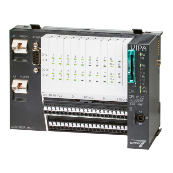
VIPA System SLIO Hardware description Structure > Interfaces 3.2 Structure 3.2.1 Compact CPU CPU 013C Locking lever X1: Ethernet PG/OP channel 1 X3: MPI(PtP) interface LEDs integrated IO periphery X2: Ethernet PG/OP channel 2 X4, X5: Connector IO part LED status indication CPU part... - Page 42 To switch the interface X3 MPI(PtP) to PROFIBUS functionality you have to activate the according bus functionality by means of a VSC storage media from VIPA. By plugging the VSC storage card and then an overall Ä Chapter 4.15 ‘Deploy- reset the according functionality is activated.
- Page 43 VIPA System SLIO Hardware description Structure > Interfaces X4: Connector Function Type Description AI 0 AI0: Analog input AI 0 AI 1 AI1: Analog input AI 1 Analog 0V 4M: GND for analog inputs DI 0 +0.0: Digital input DI 0 / Counter 0 (A) * DI 1 +0.1: Digital input DI 1 / Counter 0 (B) / Frequency 0 *...
- Page 44 VIPA System SLIO Hardware description Structure > Interfaces X5: Connector Function Type Description Sys DC 24V 1L+: DC 24V for electronic section supply Sys 0V 1M: GND for electronic section supply reserved DC 24V S+: DC 24V for sensor 1M: GND for sensor DO 0 +0.0: Digital output DO 0 / PWM 0 / Output channel counter 0...
-
Page 45: Memory Management
There is the possibility to extend the work memory to its maximum capacity 128kbyte by means of a VSC. 3.2.4 Slot for storage media Overview In this slot you can insert the following storage media: VSD - VIPA SD-Card – External memory card for programs and firmware. VSC - VIPASetCard –... -
Page 46: Operating Mode Switch
VIPA System SLIO Hardware description Structure > LEDs CAUTION! Please connect the CPU for approximately 1 hour to the power supply, so that the internal buffering mechanism is loaded accordingly. In case of failure of the buffer mechanism Date and Time 01.09.2009 00:00:00 set. - Page 47 VIPA System SLIO Hardware description Structure > LEDs Description green yellow yellow yellow Overall reset Overall reset is requested Overall reset is executed. Overall reset with none hardware configuration respectively hard- ware configuration from memory card. 10Hz Factory reset Reset to factory setting is executed.
- Page 48 VIPA System SLIO Hardware description Structure > LEDs Master operation Description (Data Exchange) (bus error) green Master has no project, this means the interface is deactivated respectively the master configured without slaves with no errors. CPU is in STOP state, the master is in "clear" state. All the slaves are in DE and the outputs are of the slaves are disabled.
- Page 49 VIPA System SLIO Hardware description Structure > LEDs I/O periphery Digital input Description green DI +0.0 ... DI +0.7 Digital input I+0.0 ... 0.7 has "1" signal Digital input I+0.0 ... 0.7 has "0" signal DI +1.0 ... DI +1.7 Digital input I+1.0 ...
-
Page 50: Technical Data
VIPA System SLIO Hardware description Technical data 3.3 Technical data Order no. 013-CCF0R00 Type CPU 013C Module ID Technical data power supply Power supply (rated value) DC 24 V Power supply (permitted range) DC 20.4...28.8 V Reverse polarity protection ü... - Page 51 VIPA System SLIO Hardware description Technical data Order no. 013-CCF0R00 Initial data size 16 Bit Technical data digital outputs Number of outputs Cable length, shielded 1000 m Cable length, unshielded 600 m Rated load voltage DC 24 V Reverse polarity protection of rated load voltage ü...
- Page 52 VIPA System SLIO Hardware description Technical data Order no. 013-CCF0R00 Rated load voltage Reverse polarity protection of rated load voltage Current consumption from load voltage L+ (without load) Voltage inputs ü Min. input resistance (voltage range) 100 kΩ Input voltage ranges 0 V ...
- Page 53 VIPA System SLIO Hardware description Technical data Order no. 013-CCF0R00 Thermocouple ranges Operational limit of thermocouple ranges Operational limit of thermocouple ranges with SFU Basic error limit thermoelement ranges Basic error limit thermoelement ranges with SFU Destruction limit thermocouple inputs...
- Page 54 VIPA System SLIO Hardware description Technical data Order no. 013-CCF0R00 Radical error limit current ranges with SFU Destruction limit against external applied voltage Settling time for ohmic load Settling time for capacitive load Settling time for inductive load Resolution in bit...
- Page 55 VIPA System SLIO Hardware description Technical data Order no. 013-CCF0R00 Hardware configuration Racks, max. Modules per rack, max. total max. 64 minus number line extensions Number of integrated DP master Number of DP master via CP Operable function modules Operable communication modules PtP...
- Page 56 VIPA System SLIO Hardware description Technical data Order no. 013-CCF0R00 Timers/Counters and their retentive characteristics Number of S7 counters S7 counter remanence adjustable 0 up to 256 S7 counter remanence adjustable C0 .. C7 Number of S7 times S7 times remanence...
- Page 57 VIPA System SLIO Hardware description Technical data Order no. 013-CCF0R00 Digital outputs central Integrated digital inputs Integrated digital outputs Analog inputs Analog outputs Analog inputs, central Analog outputs, central Integrated analog inputs Integrated analog outputs Number of outputs Output voltage (typ) L+ (-1.5 V)
- Page 58 VIPA System SLIO Hardware description Technical data Order no. 013-CCF0R00 Electrically isolated ü ü MP²I (MPI/RS232) DP master DP slave optional Point-to-point interface ü 5V DC Power supply max. 90mA, isolated 24V DC Power supply max. 100mA, non-isolated Type Type of interface...
- Page 59 VIPA System SLIO Hardware description Technical data Order no. 013-CCF0R00 S7 communication as server ü S7 communication as client Activation/deactivation of DP slaves Direct data exchange (slave-to-slave communication) DPV1 ü Transmission speed, min. 9.6 kbit/s Transmission speed, max. 12 Mbit/s Number of DP slaves, max.
- Page 60 VIPA System SLIO Hardware description Technical data Order no. 013-CCF0R00 Cable length, max. 500 m Point-to-point protocol ASCII protocol ü STX/ETX protocol ü 3964(R) protocol ü RK512 protocol USS master protocol ü Modbus master protocol ü Modbus slave protocol ü...
- Page 61 VIPA System SLIO Hardware description Technical data Order no. 013-CCF0R00 User data per TCP connection, max. 8 KB ISO on TCP connections (RFC 1006) FETCH PASSIV, WRITE PASSIV, Connection of passive data handling User data per ISO connection, max. 8 KB Ethernet open communication via PG/OP Number of configurable connections, max.
-
Page 62: Deployment Cpu 013-Ccf0R00
VIPA System SLIO Deployment CPU 013-CCF0R00 Start-up behavior Deployment CPU 013-CCF0R00 4.1 Assembly Ä Chapter 2 ‘Basics and Information about assembly and cabling mounting’ on page 10. 4.2 Start-up behavior Turn on power supply The CPU checks whether a project AUTOLOAD.WLD exists on the memory card. If so, an overall reset is executed and the project is automatically loaded from the memory card. -
Page 63: Addressing
VIPA System SLIO Deployment CPU 013-CCF0R00 Addressing > Default address assignment of the I/O part 4.3 Addressing 4.3.1 Overview To provide specific addressing of the installed peripheral modules, certain addresses must be allocated in the CPU. This address mapping is in the CPU as hardware configu- ration. -
Page 64: Addressing Periphery Modules
VIPA System SLIO Deployment CPU 013-CCF0R00 Addressing > Addressing periphery modules 4.3.3 Addressing periphery modules The CPU 013-CCF0R00 provides an periphery area (address 0 ... 2047) and a process image of the in- and outputs (each address default 0 ... 127). The size of the process Ä... -
Page 65: Hardware Configuration - Cpu
The configuration of the System SLIO CPU happens in the Siemens SIMATIC Man- ager by means of a virtual PROFINET IO device ‘VIPA SLIO CPU’ . The ‘VIPA SLIO System’ is to be installed in the hardware catalog by means of the GSDML. - Page 66 è Additional field devices è I/O è VIPA SLIO System’ and connect the IO device ‘013-CCF0R00 CPU’ to your PROFINET system. ð In the slot overview of the PROFINET IO device ‘VIPA SLIO CPU’ the CPU is already placed at slot 0. From slot 1 you can place your System SLIO modules.
-
Page 67: Hardware Configuration - System Slio Modules
Perform, if not already done, a hardware configuration for the CPU. ‘Hardware configuration - CPU’ on page 65 Starting with slot 1 place in the slot overview of the PROFINET IO device "VIPA SLIO CPU" your System SLIO modules in the plugged sequence. -
Page 68: Hardware Configuration - Ethernet Pg/Op Channel
VIPA System SLIO Deployment CPU 013-CCF0R00 Hardware configuration - Ethernet PG/OP channel 4.6 Hardware configuration - Ethernet PG/OP channel Overview The CPU 013-CCF0R00 has an integrated Ethernet PG/OP channel. This channel allows you to program and remote control your CPU. -
Page 69: Time-Of-Day Synchronization
VIPA System SLIO Deployment CPU 013-CCF0R00 Hardware configuration - Ethernet PG/OP channel > Time-of-day synchronization To get the stations and their MAC address, use the [Browse] button or type in the MAC Address. The Mac address may be found at the 1. label beneath the front flap of the CPU. -
Page 70: Setting Standard Cpu Parameters
CPU 314-6EH04 314-6EH04-0AB0 V3.3) in the Siemens hardware configurator, the standard parameters of the VIPA CPU may be set with "Object properties" of the CPU 314C-2 PN/DP during hardware configuration. Via a double-click on the CPU 314C-2 PN/DP the parameter window of the CPU may be accessed. - Page 71 VIPA System SLIO Deployment CPU 013-CCF0R00 Setting standard CPU parameters > Parameter CPU General Short description – The short description of the Siemens CPU is CPU 314C-2 PN/DP (314-6EH04-0AB0 V3.3). Order No. / Firmware – Order number and firmware are identical to the details in the "hardware catalog"...
- Page 72 – The VIPA CPU is preset such that OB 85 is not called if an I/O access error occurs and no entry is made in the diagnostic buffer either.
-
Page 73: Parameter For Mpi/Dp
VIPA System SLIO Deployment CPU 013-CCF0R00 Setting standard CPU parameters > Parameter for MPI/DP Cyclic interrupts Priority – Here the priorities may be specified according to which the corresponding cyclic interrupt is processed. Execution – Enter the time intervals in ms, in which the watchdog interrupt OBs should be pro- cessed. -
Page 74: Setting Vipa Specific Cpu Parameters
CPU 314C-2 PN/DP (314-6EH04-0AB0 V3.3) from Siemens. After the hardware configuration of the CPU you can set the parameters of the CPU in the virtual IO device ‘VIPA SLIO CPU’ . Via double-click at the VIPA SLIO CPU the prop- erties dialog is opened... - Page 75 VIPA System SLIO Deployment CPU 013-CCF0R00 Setting VIPA specific CPU parameters VIPA specific parameters The following parameters may be accessed by means of the properties dialog of the VIPA CPU. Function X3 – MPI/DP (default): In this operating mode parameters are active, which you set on Ä...
-
Page 76: Project Transfer
This means the same rules are valid and you use the same components for the build-up. The single participants are connected with each other via bus interface plugs and PROFIBUS cables. Per default the MPI net runs with 187.5kbaud. VIPA CPUs are deliv- ered with MPI address 2. -
Page 77: Transfer Via Ethernet
Switch to the register Local connection. Set the COM port of the PCs and the transfer rate 38400baud for the MPI program- ming cable from VIPA. Transfer your project via ‘PLC è Load to module’ via MPI to the CPU and save it with ‘PLC è... -
Page 78: Accessing The Web Server
VIPA System SLIO Deployment CPU 013-CCF0R00 Accessing the web server > Web page with selected CPU Copy the blocks from the project blocks folder and the System data into the wld file. Copy the wld file at a suited memory card. Plug this into your CPU and start it again. - Page 79 VIPA System SLIO Deployment CPU 013-CCF0R00 Accessing the web server > Web page with selected CPU Info - Overview Here order number, serial number and the version of firmware and hardware of the CPU are listed. [Expert View] takes you to the advanced "Expert View".
- Page 80 VIPA System SLIO Deployment CPU 013-CCF0R00 Accessing the web server > Web page with selected CPU VSC Information VSC Product Number 955-C000M20 Information via VSC VSC Product S/N 00001055 Memory Extension 64 kByte Profibus PB Master Active Feature Set Information...
-
Page 81: Web Page With Selected Module
VIPA System SLIO Deployment CPU 013-CCF0R00 Accessing the web server > Web page with selected module CPU Firmware Information syslibex.wld Protect.wld ARM Processor Load Measurement Cycle Time 100 ms Information for the support Last Value Average Of Last 10 Values... -
Page 82: Operating Modes
VIPA System SLIO Deployment CPU 013-CCF0R00 Operating modes > Overview 4.11 Operating modes 4.11.1 Overview The CPU can be in one of 4 operating modes: Operating mode STOP Operating mode START-UP (OB 100 - restart / OB 102 - cold start *) -
Page 83: Function Security
(parameterizable min. 1ms) that stop res. execute a RESET at the CPU in case of an error and set it into a defined STOP state. The VIPA CPUs are devel- oped function secure and have the following system properties:... - Page 84 VIPA System SLIO Deployment CPU 013-CCF0R00 Operating modes > Function security Event concerns Effect RUN ® STOP general BASP (Befehls-Ausgabe-Sperre, i.e. command output lock) is set. central digital outputs The outputs are disabled. central analog outputs The outputs are disabled.
-
Page 85: Overall Reset
4.12.3 Actions after a memory reset Activating functionality by If there is a VSC from VIPA plugged, after an overall reset the according functionality is Ä ‘VSD’ on page 89 means of a VSC automatically activated. -
Page 86: Firmware Update
LEDs and the firmware may be installed by an update request. Current firmware at The latest firmware versions can be found in the service area at www.vipa.com. For www.vipa.com example the following files are necessary for the firmware update of the CPU 013- CCF0R00 and its components with hardware release 01: CPU 013C, Hardware release 01: Px000265.pkg... - Page 87 VIPA System SLIO Deployment CPU 013-CCF0R00 Firmware update CAUTION! With a firmware update an overall reset is automatically executed. If your program is only available in the load memory of the CPU it is deleted! Save your program before executing a firmware update! After a firmware Ä...
-
Page 88: Reset To Factory Settings
Deployment storage media - VSD, VSC Overview At the front of the CPU there is a slot for storage media. Here the following storage media can be plugged: VSD - VIPA SD-Card – External memory card for programs and firmware. VSC - VIPASetCard –... - Page 89 VIPA System SLIO Deployment CPU 013-CCF0R00 Deployment storage media - VSD, VSC You can cause the CPU to load a project automatically respectively to execute a com- mand file by means of pre-defined file names. VSDs are external storage media based on SD memory cards. VSDs are pre-formatted with the PC format FAT 16 (max.
-
Page 90: Extended Know-How Protection
"Operation list". 4.16 Extended know-how protection Overview Besides the "standard" Know-how protection the CPUs from VIPA provide an "extended" know-how protection that serves a secure block protection for accesses of 3. persons. Standard protection – The standard protection from Siemens transfers also protected blocks to the PG but their content is not displayed. -
Page 91: Cmd - Auto Commands
VIPA System SLIO Deployment CPU 013-CCF0R00 CMD - auto commands Ä Chapter 4.12 Plug the memory card into the CPU and execute an overall reset. ‘Overall reset’ on page 85 ð The overall reset stores the blocks in protect.wld permanently in the CPU pro- tected from accesses of 3. - Page 92 VIPA System SLIO Deployment CPU 013-CCF0R00 CMD - auto commands Command Description Diagnostics entry SAVE_PROJECT The recent project (blocks and hardware configuration) is stored 0xE806 as "s7prog.wld" at the memory card. If the file just exists it is renamed to "s7prog.old". If your CPU is password protected so you have to add this as parameter.
-
Page 93: Control And Monitoring Of Variables With Test Functions
VIPA System SLIO Deployment CPU 013-CCF0R00 Control and monitoring of variables with test functions The parameters IP address, subnet mask and gateway may be received from the system administrator. Enter the IP address if there is no gateway used. 4.18... -
Page 94: Diagnostic Entries
Ä Appendix ‘System specific event IDs’ on page 222 You may read the diagnostics buffer of the CPU via the Siemens SIMATIC Manager. Besides of the standard entries in the diagnostics buffer, the VIPA CPUs support some additional specific entries as Event-IDs. -
Page 95: Deployment I/O Periphery
VIPA System SLIO Deployment I/O periphery Overview Deployment I/O periphery 5.1 Overview Project engineering and On this CPU the connectors for digital respectively analog signal and Technological parametrization functions are combined in a one casing. The project engineering happens in the Siemens SIMATIC Manager as Siemens CPU 314C-2 PN/DP (314-6EH04-0AB0 V3.3). -
Page 96: Address Assignment
VIPA System SLIO Deployment I/O periphery Address assignment 5.2 Address assignment Sub module Input Access Description address AI5/AO2 WORD Analog input channel 0 (X4) WORD Analog input channel 1 (X4) Sub module Input Access Description address DI24/DO16 BYTE Digital input I+0.0 ... I+0.7 (X4) BYTE Digital input I+1.0 ... -
Page 97: Analog Input
VIPA System SLIO Deployment I/O periphery Analog input > Analog value representation 5.3 Analog input 5.3.1 Properties 2xUx12Bit (0 ... 10V) fixed. The analog channels of the module are not isolated to the electronic power supply. The analog part has no status indication. -
Page 98: Wiring
VIPA System SLIO Deployment I/O periphery Analog input > Wiring Voltage measurement 0 ... 10V Measuring range Voltage Decimal Range Formulas 0 ... 10V > 11.759V 32767 7FFFh overflow 11.759V 32511 7EFFh overdrive range 27648 6C00h nominal range 13824 3600h... -
Page 99: Parametrization
VIPA System SLIO Deployment I/O periphery Analog input > Parametrization 5.3.4 Parametrization 5.3.4.1 Adress assignment Sub module Input Access Description address AI5/AO2 WORD Analog input channel 0 (X4) WORD Analog input channel 1 (X4) 5.3.4.2 Filter Parameter hardware con- The analog input part has a filter integrated. The parametrization of the filter happens in figuration the Siemens SIMATIC Manager via the parameter ‘Integration time’... -
Page 100: Digital Input
VIPA System SLIO Deployment I/O periphery Digital input > Wiring 5.4 Digital input 5.4.1 Properties 16xDC 24V Maximum input frequency – 10 inputs: 100kHz – 6 inputs: 1kHz Interrupt functions parameterizable Status indication via LEDs 5.4.2 Wiring X4: Connector Function... -
Page 101: Parametrization
VIPA System SLIO Deployment I/O periphery Digital input > Parametrization 5.4.3 Parametrization 5.4.3.1 Adress assignment Sub module Input Access Description address DI24/DO16 BYTE Digital input I+0.0 ... I+0.7 (X4) BYTE Digital input I+1.0 ... I+1.7 (X4) 5.4.3.2 Hardware interrupt Parameter hardware con- With the parameter ‘Hardware interrupt at ...’... -
Page 102: Status Indication
VIPA System SLIO Deployment I/O periphery Digital input > Status indication 5.4.4 Status indication Digital input Description green DI +0.0 DI +0.7 Digital I+0.0 ... 0.7 has "1" signal Digital I+0.0 ... 0.7 has "0" signal DI +1.0 ... DI +1.7 Digital I+1.0 ... -
Page 103: Digital Output
VIPA System SLIO Deployment I/O periphery Digital output > Wiring 5.5 Digital output 5.5.1 Properties 12xDC 24V, 0.5A Status indication via LEDs 5.5.2 Wiring X5: Connector Function Type Description Sys DC 24V 1L+: DC 24V for electronic section supply Sys 0V... -
Page 104: Parametrization
VIPA System SLIO Deployment I/O periphery Digital output > Status indication 5.5.3 Parametrization 5.5.3.1 Address assignment Sub module Output Access Description address DI24/DO16 BYTE Digital output Q+0.0 ... Q+0.7 (X5) BYTE Digital output Q+1.0 ... Q+1.3 (X5) 5.5.4 Status indication... -
Page 105: Counting
VIPA System SLIO Deployment I/O periphery Counting > Wiring 5.6 Counting 5.6.1 Properties 4 channels Various counting modes – once – continuously – periodically Control by the user program via blocks 5.6.2 Wiring 5.6.2.1 Counter inputs X4: Connector Function Type... - Page 106 VIPA System SLIO Deployment I/O periphery Counting > Wiring For not all inputs are available at the same time, for every counter you may define the input assignment via the parameterization for the following input signals: Counter – Pulse input for counter signal respectively track A of an encoder for 1-, 2- or 4-fold evaluation.
-
Page 107: Proceeding
SW gate by setting the SW gate of the SFB 47. You can also activate input ‘Gate 3’ via the parametrization for Counter 3. More information about the usage of this block may be found in the manual "SPEED7 Operation List" from VIPA. 5.6.4 Parametrization 5.6.4.1... - Page 108 Please consider that the range of values could be limited due to the used projecting tool. With the VIPA SPEED7 Studio there are no limitations. Ä Chapter 9 ‘Configuration with VIPA SPEED7 Studio’ on page 185 HB300 | CPU | 013-CCF0R00 | en | 17-20...
- Page 109 VIPA System SLIO Deployment I/O periphery Counting > Parametrization Parameter overview Operating parameters Description Assignment Main count direction None No restriction of the counting range None Up: Restricts the up-counting range. The counter starts from 0 or load value, counts in positive direction up to the declaration end value -1 and then jumps back to load value at the next positive transducer pulse.
- Page 110 VIPA System SLIO Deployment I/O periphery Counting > Parametrization Input Description Assignment Signal evaluation Specify the signal of the connected encoder: Pulse/direction Pulse/direction At the input count and direction signal are connected At the input there is an encoder connected with the fol- lowing evaluation: –...
- Page 111 VIPA System SLIO Deployment I/O periphery Counting > Parametrization Hardware interrupt Description Assignment Hardware gate opening Hardware interrupt by edge 0-1 exclusively at HW gate disabled channel 3 enabled: Process interrupt by edge 0-1 exclusively at HW gate channel 3 with open SW gate...
-
Page 112: Counter Operating Modes
VIPA System SLIO Deployment I/O periphery Counting > Counter operating modes 5.6.5 Counter operating modes 5.6.5.1 Count continuously In this operating mode the counter counts starting with the load value. When the counter counts forward and reaches the upper count limit and another counting pulse in positive direction arrives, it jumps to the lower count limit and counts from there on. - Page 113 VIPA System SLIO Deployment I/O periphery Counting > Counter operating modes 5.6.5.2 Count once 5.6.5.2.1 No main counting direction The counter counts once starting with load value. It is counted forward or backward. The counter limits are fix set to maximum range.
- Page 114 VIPA System SLIO Deployment I/O periphery Counting > Counter operating modes 5.6.5.2.2 Main counting direction forward The counter counts forward starting with the load value. When the counter reaches the End value -1 in positive direction, it jumps to the load value at the next count pulse and the gate is automatically closed.
- Page 115 VIPA System SLIO Deployment I/O periphery Counting > Counter operating modes 5.6.5.2.3 Main counting direction backward The counter counts backward starting with the load value. When the counter reaches the End value +1 in positive direction, it jumps to the load value at the next count pulse and the gate is automatically closed.
- Page 116 VIPA System SLIO Deployment I/O periphery Counting > Counter operating modes 5.6.5.3 Count periodically 5.6.5.3.1 No main counting direction The counter counts forward or backwards starting with the load value. At over- or underrun at the count limits, the counter jumps to the load value and con- tinues counting.
- Page 117 VIPA System SLIO Deployment I/O periphery Counting > Counter operating modes 5.6.5.3.2 Main counting direction forward The counter counts forward starting with the load value. When the counter reaches the end value -1 in positive direction, it jumps to the load value at the next positive count pulse and continues counting.
- Page 118 VIPA System SLIO Deployment I/O periphery Counting > Counter operating modes 5.6.5.3.3 Main counting direction backward Main counting direction backward The counter counts backward starting with the load value. When the counter reaches the end value +1 in positive direction, it jumps to the load value at the next negative count pulse and continues counting.
-
Page 119: Counter - Additional Functions
VIPA System SLIO Deployment I/O periphery Counting > Counter - Additional functions 5.6.6 Counter - Additional functions 5.6.6.1 Overview Schematic structure The illustration shows how the additional functions influence the counting behavior. The following pages describe these additional functions in detail: 5.6.6.2... - Page 120 VIPA System SLIO Deployment I/O periphery Counting > Counter - Additional functions At interrupt function, the counter starts counting with the last recent counter value after gate restart. Counter 0 ... 2 SW gate Gate function Reaction counter 0 ... 2...
- Page 121 VIPA System SLIO Deployment I/O periphery Counting > Counter - Additional functions 5.6.6.4 Additional functions counter 3 Exclusively counter 3 has the following additional functions: HW gate via Gate 3 Latch function 5.6.6.4.1 HW gate via Gate 3 Starting, stopping and interrupting a count function of counter 3 happens via the internal gate (I gate).
- Page 122 VIPA System SLIO Deployment I/O periphery Counting > Counter - Additional functions 5.6.6.5 Counter output channel Characteristics of the Each counter has an output channel. You pre-define the behavior of the counter output output via the parametrization: no comparison: –...
- Page 123 VIPA System SLIO Deployment I/O periphery Counting > Counter - Additional functions ³ Effect at counter value comparison value Counter value ³ comparison value ® output is set and hysteresis activated Leave hysteresis range ® output is reset Counter value ³ comparison value ® output is set and hysteresis activated Leave hysteresis range, output remains set for counter value ³...
- Page 124 VIPA System SLIO Deployment I/O periphery Counting > Counter - Additional functions Counter value = comparison value ® output is set and hysteresis activated Output is reset for leaving hysteresis range and counter value > comparison value Counter value = comparison value ® output is set and hysteresis activated Counter value = comparison value and hysteresis active ®...
-
Page 125: Diagnostics And Interrupt
Integration time 10ms ... 10000ms in steps of 1ms configurable Control by the user program via SFB 48 More information about the usage of this block may be found in the manual "SPEED7 Operation List" from VIPA. Integration time Counting pulse... -
Page 126: Wiring
VIPA System SLIO Deployment I/O periphery Frequency measurement > Wiring Integration time Counting pulse SW gate Evaluated frequency The counting function is disabled during the pulse width modulation on the same channel. 5.7.2 Wiring 5.7.2.1 Frequency measurement inputs Schließen Sie für die Frequenzmessung das zu messende Signal an den B-Eingang des entsprechenden Zählers an. -
Page 127: Proceeding
VIPA System SLIO Deployment I/O periphery Frequency measurement > Parametrization 5.7.3 Proceeding Hardware configuration In the Siemens SIMATIC Manager the following steps should be executed: Perform a hardware configuration for the CPU. Ä Chapter 4.4 ‘Hardware configura- tion - CPU’ on page 65 Double-click the counter sub module of the CPU 314C-2 PN/DP. - Page 128 VIPA System SLIO Deployment I/O periphery Frequency measurement > Parametrization 5.7.4.2 Interrupt selection Via ‘Basic parameters’ you can reach ‘Select interrupt’ . Here you can define the inter- rupts the CPU will trigger. The following parameters are supported: None: The interrupt function is de-activated.
-
Page 129: Status Indication
VIPA System SLIO Deployment I/O periphery Frequency measurement > Status indication 5.7.5 Status indication Digital input Description green DI +0.0 ... DI +0.7 Digital input I+0.0 ... 0.7 has "1" signal Digital input I+0.0 ... 0.7 has "0" signal DI +1.0 ... DI +1.7 Digital input I+1.0 ... -
Page 130: Pulse Width Modulation - Pwm
Channel 0 and 1 are supported Control by the user program via SFB 49 More information about the usage of this block may be found in the manual "SPEED7 Operation List" from VIPA. Period On-delay Pulse duration... -
Page 131: Proceeding
VIPA System SLIO Deployment I/O periphery Pulse width modulation - PWM > Parametrization Function Type Description 2M: GND for PWM DC 24V 3L+: DC 24V SLIO bus power section supply 3M: GND SLIO bus power section supply 5.8.3 Proceeding Hardware configuration PWM and pulse train output use the same hardware configuration. - Page 132 VIPA System SLIO Deployment I/O periphery Pulse width modulation - PWM > Parametrization Sub module Output Access Description address Counter DWORD reserved DWORD reserved DWORD reserved DWORD reserved 5.8.4.2 Pulse width modulation Parameter hardware con- Default values and structure of this dialog box depend on the selected ‘Operating mode’ .
-
Page 133: Status Indication
VIPA System SLIO Deployment I/O periphery Pulse width modulation - PWM > Status indication Operating parameters Description Assignment Period With the period you define the length of the output sequence, which consists of pulse duration and pulse pause. Range of values: Time base 1ms: 1 ... -
Page 134: Pulse Train
Channel 0 and 1 are supported Control by the user program via SFB 49 More information about the usage of this block may be found in the manual "SPEED7 Operation List" from VIPA. Number of pulses Period duration Pulse duration... -
Page 135: Wiring
VIPA System SLIO Deployment I/O periphery Pulse train > Proceeding 5.9.2 Wiring 5.9.2.1 Pulse train outputs X5: Connector Function Type Description Sys DC 24V 1L+ DC 24V for electronic section supply Sys 0V 1M: GND for electronic section supply DO 0.0 Pulse train 0 DO 0.1... -
Page 136: Parametrization
VIPA System SLIO Deployment I/O periphery Pulse train > Parametrization User program The SFB 49 should cyclically be called (e.g. OB 1) for controlling the pulse train output. – The SFB 49 is used for PWM and pulse train output. -
Page 137: Status Indication
VIPA System SLIO Deployment I/O periphery Pulse train > Status indication Parameter overview Operating parameters Description Assignment Output format Here specify the range of values for the output. The CPU Per mil hereby determines the pulse duration: Per mil –... -
Page 138: Diagnostic And Interrupt
Closing the HW gate with open SW gate - except for counter 3 Diagnostics interrupt The VIPA specific parameters allow you to define the following trigger for a diagnostics Ä Chapter 4.8 ‘Setting VIPA specific CPU parameters’ on page 74:... - Page 139 VIPA System SLIO Deployment I/O periphery Diagnostic and interrupt > Process interrupt Local double word 8 of OB 40 at Alarm Inputs Local byte Bit 7...0 Bit 0: Edge at I+0.0 Bit 1: Edge at I+0.1 Bit 2: Edge at I+0.2 Bit 3: Edge at I+0.3...
-
Page 140: Diagnostic Interrupt
VIPA System SLIO Deployment I/O periphery Diagnostic and interrupt > Diagnostic interrupt Local double word 8 of OB 40 at frequency measurement Local byte Bit 7...0 Bit 0: End of measurement channel 0 (end of the integration time) Bit 7 ... 1: 0 (fix) Bit 0: End of measurement channel 1 (end of the integration time) Bit 7 ... - Page 141 VIPA System SLIO Deployment I/O periphery Diagnostic and interrupt > Diagnostic interrupt Example: Diagnostic interrupt pro- Every OB 82 call causes an entry in the diagnostic buffer of the CPU containing error cessing cause and module address. By using the SFC 59 you may read the diagnostic bytes. At de-activated diagnostic interrupt you have access to the last recent diagnostic event.
- Page 142 VIPA System SLIO Deployment I/O periphery Diagnostic and interrupt > Diagnostic interrupt Record set 0 Byte Bit 7...0 Diagnostic incoming Bit 0: set at module failure – Counter/Frequency measurement: Process interrupt lost – Digital input: Process interrupt lost – Missing power supply DI or DO –...
- Page 143 VIPA System SLIO Deployment I/O periphery Diagnostic and interrupt > Diagnostic interrupt Record set 0 After the removing error a diagnostic message takes place if the diagnostic interrupt outgoing Diagnostic release is still active. outgoing Byte Bit 7...0 Bit 0: set at module failure –...
- Page 144 VIPA System SLIO Deployment I/O periphery Diagnostic and interrupt > Diagnostic interrupt Diagnostic record set 1 at The record set 1 contains the 4byte of the record set 0 and additionally 12byte module Alarm Inputs specific diagnostic data. The diagnostic bytes have the following assignment: Byte Bit 7...0...
- Page 145 VIPA System SLIO Deployment I/O periphery Diagnostic and interrupt > Diagnostic interrupt Byte Bit 7...0 Diagnostic interrupt due to "process interrupt lost" at... Bit 0: ... input I+1.4 Bit 1: 0 (fix) Bit 2: ... input I+1.5 Bit 3: 0 (fix) Bit 4: ...
- Page 146 VIPA System SLIO Deployment I/O periphery Diagnostic and interrupt > Diagnostic interrupt Byte Bit 7...0 Diagnostic interrupt due to "process interrupt lost" at... Bit 0: Gate counter 3 open (activated) Bit 1: Gate counter 3 closed Bit 2: Over-/underflow/end value counter 3...
-
Page 147: Deployment Ptp Communication
CPU. Use FCs instead SFCs Please regard that the special VIPA SFCs are not shown in the SLIO CPU. Please use for programming tools e.g. Siemens SIMATIC Manager and TIA Portal the according FCs of the VIPA library. -
Page 148: Principle Of The Data Transfer
VIPA System SLIO Deployment PtP communication Principle of the data transfer 6.2 Principle of the data transfer RS485 PtP communication The data transfer is handled during runtime by using FC/SFCs. The principle of data transfer is the same for all protocols and is shortly illustrated in the following. -
Page 149: Enable Ptp Functionality
Proceeding After the set the parameters of the CPU in the virtual IO device ‘VIPA SLIO CPU’ . Open the properties dialog by a double-click at ‘VIPA SLIO CPU’ . ð The VIPA specific parameters may be accessed by means of the properties dialog. -
Page 150: Deployment Of Rs485 Interface For Ptp
VIPA System SLIO Deployment PtP communication Deployment of RS485 interface for PtP 6.4 Deployment of RS485 interface for PtP Properties RS485 Logical states represented by voltage differences between the two cores of a twisted pair cable Serial bus connection in two-wire technology using half duplex mode Data communications up to a max. -
Page 151: Parametrization
VIPA System SLIO Deployment PtP communication Communication > FC/SFC 218 - SER_RCV - Receive from PtP Connection RS485 interface Periphery 6.5 Parametrization 6.5.1 FC/SFC 216 - SER_CFG - Parametrization PtP The parametrization happens during runtime deploying the FC/SFC 216 (SER_CFG). You have to store the parameters for STX/ETX, 3964R, USS and Modbus in a DB. -
Page 152: Protocols And Procedures
VIPA System SLIO Deployment PtP communication Protocols and procedures More information about the usage of these blocks may be found in the manual "SPEED7 Operation List" from VIPA. 6.7 Protocols and procedures Overview The CPU supports the following protocols and procedures:... - Page 153 VIPA System SLIO Deployment PtP communication Protocols and procedures 3964 The 3964R procedure controls the data transfer of a point-to-point link between the CPU and a communication partner. The procedure adds control characters to the message data during data transfer. These control characters may be used by the communication partner to verify the complete and error free receipt.
- Page 154 VIPA System SLIO Deployment PtP communication Protocols and procedures The communication happens exclusively in half-duplex operation. After a send command, the acknowledgement telegram must be read by a call of the FC/SFC 218 SER_RCV. The telegrams for send and receive have the following structure:...
-
Page 155: Modbus - Function Codes
Normally the access at Modbus happens by means of the ranges 0x, 1x, 3x and 4x. 0x and 1x gives you access to digital bit areas and 3x and 4x to analog word areas. For the CPs from VIPA is not differentiating digital and analog data, the following assign- ment is valid:... - Page 156 VIPA System SLIO Deployment PtP communication Modbus - Function codes 0x - Bit area for master output data Access via function code 01h, 05h, 0Fh 1x - Bit area for master input data Access via function code 02h 3x - word area for master input data...
- Page 157 VIPA System SLIO Deployment PtP communication Modbus - Function codes Respond of the slave If the slave announces an error, the function code is send back with an "ORed" 80h. Without an error, the function code is sent back. ® Error...
- Page 158 VIPA System SLIO Deployment PtP communication Modbus - Function codes Command telegram Slave address Function code Address 1. bit Number of words Check sum CRC/LRC 1byte 1byte 1word 1word 1word Respond telegram Slave address Function code Number of Data 1. word Data 2.
- Page 159 VIPA System SLIO Deployment PtP communication Modbus - Function codes Please regard that the number of bits has additionally to be set in byte. Command telegram Slave Function Address 1. Number of Number of Data 1. Data 2. Check sum...
-
Page 160: Deployment Pg/Op Communication - Productive
VIPA System SLIO Deployment PG/OP communication - productive Basics - Industrial Ethernet in automation Deployment PG/OP communication - productive 7.1 Basics - Industrial Ethernet in automation Overview The flow of information in a company presents a vast spectrum of requirements that must be met by the communication systems. -
Page 161: Basics - Iso/Osi Reference Model
VIPA System SLIO Deployment PG/OP communication - productive Basics - ISO/OSI reference model 7.2 Basics - ISO/OSI reference model Overview The ISO/OSI reference model is based on a proposal that was developed by the Interna- tional Standards Organization (ISO). This represents the first step towards an interna- tional standard for the different protocols. -
Page 162: Basics - Terms
VIPA System SLIO Deployment PG/OP communication - productive Basics - Terms Layer 5 - Session layer The session layer is also called the communication control layer. It relieves the communi- cation between service deliverer and the requestor by establishing and holding the con- nection if the transport system has a short time fail out. -
Page 163: Basics - Protocols
The acknowledgement of the data transfer is established from the partner station at level 7 of the ISO/OSI reference model. At the PLC side FB/SFB VIPA handling blocks are necessary for data transfer for the Siemens S7 connections. More information about the usage of these blocks may be found in the manual "SPEED7 Operation List"... -
Page 164: Basics - Ip Address And Subnet
VIPA System SLIO Deployment PG/OP communication - productive Basics - IP address and subnet Open communication In the ‘open communication’ the communication takes place via the user program by means of handling blocks. These blocks are also part of the Siemens SIMATIC Manager. - Page 165 VIPA System SLIO Deployment PG/OP communication - productive Basics - IP address and subnet Subnet mask binary all "1" binary all "0" IPv4 address Net-ID Host-ID Subnet mask and IPv4 address Net-ID Subnet-ID new Host-ID Address at first start-up At the first start-up of the CPU, the Ethernet PG/OP channel does not have an IP address.
-
Page 166: Fast Introduction
(Configuration and communication happens by standard handling blocks) Transfer of the complete project to CPU In the Siemens SIMATIC Manager, the CPU 013-CCF0R00 from VIPA is to be configured as CPU 314C-2 PN/DP (314-6EH04-0AB0 V3.3)! The Ethernet PG/OP channel of the CPU 013-CCF0R00 is always to be configured as CP343-1 (343-1EX30 V3.0) from Siemens at slot 4. - Page 167 "In unknown project" or via deputy objects like "Other stations" or Siemens "SIMATIC S5 Sta- tion". The communication is controlled by the user program with VIPA handling blocks. To use this blocks, configured communication connections are always necessary in the active station.
- Page 168 VIPA System SLIO Deployment PG/OP communication - productive Configure Siemens S7 connections Graphic net view: All stations and networks are displayed in a graphic view. By clicking on the according component you may access and alter the concerning prop- erties.
- Page 169 NetPro. Siemens S7 connection For data transfer with Siemens S7 connections the FB/SFB VIPA handling blocks are necessary; the deployment is described in the manual "Operation list" of your CPU. At Siemens S7 connections the communication connections are specified by a con- nection ID for each communication partner.
- Page 170 TSAP S7 connection local TSAP ß ß remote TSAP ID A ID B Combination options with deployment of the FB/SFB VIPA handling blocks Connection partner Connection establishing Connection specified in NetPro active/passive specified (in the current project) unspecified in NetPro...
- Page 171 Communication functions communication functions: Siemens S7-300 communication functions: By integration of the function blocks FB 12 ... FB 15 from VIPA you may access the Siemens S7-300 communication functions. Siemens S7-400 communication functions: For the Siemens S7-400 communication functions the SFB 12 ... SFB 15 are to be used, which were integrated to the operating system of the CPU.
-
Page 172: Configure Open Communication
VIPA System SLIO Deployment PG/OP communication - productive Configure Open Communication Function blocks FB/SFB Label Description FB/SFB 12 BSEND Sending data in blocks: FB/SFB 12 BSEND sends data to a remote partner FB/SFB of the type BRCV (FB/SFB 13). The data area to be transmitted is segmented. Each segment is sent individually to the partner. - Page 173 UDT 66* TCON_ADR Data structure for assigning addressing parameters for the remote partner *) More information about the usage of these blocks may also be found in the manual "SPEED7 Operation List" from VIPA. Designation Connection-oriented protocols: Connectionless protocol: UDP...
- Page 174 VIPA System SLIO Deployment PG/OP communication - productive Configure Open Communication The following connection-oriented protocols are supported with FBs for open communica- tion via Industrial Ethernet: TCP/IP native according to RFC 793 (connection types 01h and 11h): – During data transmission, no information about the length or about the start and end of a message is transmitted.
-
Page 175: Option: Deployment Profibus Communication
To switch the interface X3 MPI(PtP) to PROFIBUS functionality you have to activate the according bus functionality by means of a VSC storage media from VIPA. By plugging the VSC storage card and then an overall Ä Chapter 4.15 ‘Deploy- reset the according functionality is activated. -
Page 176: Fast Introduction
To switch the interface X3 MPI(PtP) to PROFIBUS functionality you have to activate the according bus functionality by means of a VSC storage media from VIPA. By plugging the VSC storage card and then an overall reset the according functionality is activated. - Page 177 VIPA System SLIO Option: Deployment PROFIBUS communication Hardware configuration - CPU Proceeding With the Siemens SIMATIC Manager the following steps should be executed: Start the Siemens hardware configurator with a new project. Insert a profile rail from the hardware catalog.
-
Page 178: Deployment As Profibus Dp Master
VIPA System SLIO Option: Deployment PROFIBUS communication Deployment as PROFIBUS DP master 8.4 Deployment as PROFIBUS DP master Precondition The hardware configuration described before was established. Proceeding Open the properties dialog of the DP interface of the CPU by means of a double- click at ‘MPI/DP’... -
Page 179: Deployment As Profibus Dp Slave
VIPA System SLIO Option: Deployment PROFIBUS communication Deployment as PROFIBUS DP slave 8.5 Deployment as PROFIBUS DP slave Fast introduction In the following the deployment of the PROFIBUS section as "intelligent" DP slave on master system is described, which exclusively may be configured in the Siemens SIMATIC Manager. - Page 180 VIPA System SLIO Option: Deployment PROFIBUS communication Deployment as PROFIBUS DP slave Connect your slave system to this master system by dragging the "CPU 31x" from the hardware catalog at Configured stations onto the master system and select your slave system to be coupled.
-
Page 181: Profibus Installation Guidelines
VIPA System SLIO Option: Deployment PROFIBUS communication PROFIBUS installation guidelines 8.6 PROFIBUS installation guidelines PROFIBUS in general A PROFIBUS DP network may only be built up in linear structure. PROFIBUS DP consists of minimum one segment with at least one master and one slave. - Page 182 In PROFIBUS all participants are wired parallel. For that purpose, the bus cable must be feed-through. Via the order number 972-0DP10 you may order the bus connector "Easy- Conn" from VIPA. This is a bus connector with switchable terminating resistor and inte- grated bus diagnostic.
-
Page 183: Commissioning And Start-Up Behavior
VIPA System SLIO Option: Deployment PROFIBUS communication Commissioning and Start-up behavior Wiring [1] 1./last bus participant [2] further participants CAUTION! The terminating resistor is only effective, if the connector is installed at a bus participant and the bus participant is connected to a power supply. - Page 184 VIPA System SLIO Option: Deployment PROFIBUS communication Commissioning and Start-up behavior Online with bus parameter The DP master can be served with bus parameters by means of a hardware configura- without slave project tion. As soon as these are transferred the DP master goes online with his bus parameter.
-
Page 185: Configuration With Vipa Speed7 Studio
9.1 SPEED7 Studio - Overview SPEED7 Studio - Working In this part the project engineering of the VIPA CPU in the VIPA SPEED7 Studio is environment shown. Here only the basic usage of the SPEED7 Studio together with a VIPA CPU is shown. -
Page 186: Speed7 Studio - Work Environment
VIPA System SLIO Configuration with VIPA SPEED7 Studio SPEED7 Studio - Work environment End SPEED7 Studio Select one of the following options if you want to end the program: Main window: Click on the Close button of the SPEED7 Studio program window. - Page 187 VIPA System SLIO Configuration with VIPA SPEED7 Studio SPEED7 Studio - Work environment (1) Menu bar Most of the commands you need for working with SPEED7 Studio are provided in the menu bar. Further commands can be accessed via the context menus using the right mouse button, e.g.
-
Page 188: Project Tree
VIPA System SLIO Configuration with VIPA SPEED7 Studio SPEED7 Studio - Work environment > Project tree 9.2.1 Project tree (1) Title and author (2) Project (3) Documentation (4) PLC (5) Motion Control (6) PLC program (7) Local components (8) Field periphery (9) HMI In the project tree, you can access commands in order to add or delete objects, e.g. -
Page 189: Catalog
VIPA System SLIO Configuration with VIPA SPEED7 Studio SPEED7 Studio - Work environment > Catalog 9.2.2 Catalog (1) Switching to another view (2) Register (3) Show/hide objects (4) Search (5) Filter (6) Objects (7) Catalog information Devices and components which you want to add to the project can be selected in the cat- alog. - Page 190 VIPA System SLIO Configuration with VIPA SPEED7 Studio SPEED7 Studio - Work environment > Catalog (4) Search You can search for certain objects in the catalog. Enter a search text in the input field. ð Only those objects are displayed in the catalog which contain the search text.
-
Page 191: Speed7 Studio - Hardware Configuration - Cpu
VIPA System SLIO Configuration with VIPA SPEED7 Studio SPEED7 Studio - Hardware configuration - Ethernet PG/OP channel 9.3 SPEED7 Studio - Hardware configuration - CPU Precondition For project engineering a thorough knowledge of the SPEED7 Studio is required! Proceeding Start the SPEED7 Studio. - Page 192 VIPA System SLIO Configuration with VIPA SPEED7 Studio SPEED7 Studio - Hardware configuration - Ethernet PG/OP channel For online access to the CPU via the Ethernet PG/OP channel, valid IP address parameters have to be assigned to this. This is called "initialization".
- Page 193 VIPA System SLIO Configuration with VIPA SPEED7 Studio SPEED7 Studio - Hardware configuration - Ethernet PG/OP channel Select ‘Context menu è Determine accessible partner’. ð A dialog window opens. Select the according network interface card, which is connected to the Ethernet PG/OP channel and click at ‘Search’...
-
Page 194: Speed7 Studio - Hardware Configuration - I/O Modules
VIPA System SLIO Configuration with VIPA SPEED7 Studio SPEED7 Studio - Hardware configuration - I/O modules Confirm with [OK]. ð The IP address data are stored in your project listed in ‘Devices and networking’ at ‘Local components’ . After transferring your project your CPU can be accessed via Ethernet PG/OP channel with the set IP address data. -
Page 195: Deployment I/O Periphery
Die Project engineering happens in the VIPA SPEED7 Studio as CPU 013-CCF0R00. For parametrization of the digital I/O periphery and the technological functions the corresponding sub modules of the CPU013-CCF0R00 are to be used. -
Page 196: Digital Output
VIPA System SLIO Configuration with VIPA SPEED7 Studio Deployment I/O periphery > Counter 9.6.3.2 Parametrization in SPEED7 Studio 9.6.3.2.1 ‘I/O addresses’ Sub module Input address Access Assignment DI16/DO12 BYTE Digital input I+0.0 ... I+0.7 (X4) BYTE Digital input I+1.0 ... I+1.7 (X4) 9.6.3.2.2... - Page 197 VIPA System SLIO Configuration with VIPA SPEED7 Studio Deployment I/O periphery > Counter 9.6.5.2 Parametrization in SPEED7 Studio 9.6.5.2.1 ‘I/O addresses’ Sub module Input address Access Assignment Count DINT Channel 0: Counter value / Frequency value DINT Channel 1: Counter value / Frequency value...
- Page 198 VIPA System SLIO Configuration with VIPA SPEED7 Studio Deployment I/O periphery > Counter Parameter overview Operating parameters Description Assignment Main count direction None No restriction of the counting range None Up: Restricts the up-counting range. The counter starts from 0 or load value, counts in positive direction up to the declaration end value -1 and then jumps back to load value at the next positive transducer pulse.
- Page 199 VIPA System SLIO Configuration with VIPA SPEED7 Studio Deployment I/O periphery > Counter Input Description Assignment Signal evaluation Specify the signal of the connected encoder: Pulse/direction Pulse/direction At the input count and direction signal are connected At the input there is an encoder connected with the fol- lowing evaluation: –...
-
Page 200: Frequency Measurement
VIPA System SLIO Configuration with VIPA SPEED7 Studio Deployment I/O periphery > Frequency measurement Frequency Description Assignment Max. counting frequency Specify the max. frequency for track A/pulse, 60kHz track B/direction, Latch and HW gate Frequency shortest permissible count pulse 1kHz 400µs... - Page 201 VIPA System SLIO Configuration with VIPA SPEED7 Studio Deployment I/O periphery > Frequency measurement 9.6.6.2 Parametrization in SPEED7 Studio 9.6.6.2.1 ‘I/O addresses’ Sub module Input address Access Assignment Count DINT Channel 0: Counter value / Frequency value DINT Channel 1: Counter value / Frequency value...
-
Page 202: Pulse Width Modulation - Pwm
VIPA System SLIO Configuration with VIPA SPEED7 Studio Deployment I/O periphery > Pulse width modulation - PWM Parameter overview Operating parameters Description Assignment Integration time Specify the integration time 100ms Range of values: 10ms ... 10000ms in steps of 1ms max. - Page 203 VIPA System SLIO Configuration with VIPA SPEED7 Studio Deployment I/O periphery > Pulse width modulation - PWM 9.6.7.2.2 ‘Channel x’ Operating mode Select via ‘Channel’ the channel and select for pulse width modulation via ‘Operating mode’ the operating mode ‘Pulse width modulation’ . Default values and structure of this dialog box depend on the selected ‘Operating mode’...
-
Page 204: Pulse Train
VIPA System SLIO Configuration with VIPA SPEED7 Studio Deployment I/O periphery > Pulse Train Operating parameters Description Assignment Period With the period you define the length of the output 20000 sequence, which consists of pulse duration and pulse pause. Range of values: Time base 1ms: 1 ... - Page 205 VIPA System SLIO Configuration with VIPA SPEED7 Studio Deployment I/O periphery > Pulse Train 9.6.8.2.2 ‘Channel x’ Operating mode PWM and pulse train output use the same hardware configuration. Switching between these modes is done within the SFB 49. Select via ‘Channel x’ the channel and select for pulse train via ‘Operating mode’...
-
Page 206: Speed7 Studio - Project Transfer
This means the same rules are valid and you use the same components for the build-up. The single participants are connected with each other via bus interface plugs and PROFIBUS cables. Per default the MPI net runs with 187.5kbaud. VIPA CPUs are deliv- ered with MPI address 2. - Page 207 VIPA System SLIO Configuration with VIPA SPEED7 Studio SPEED7 Studio - Project transfer > Transfer via MPI MPI programming cable Activate the terminating resistor via switch MPI network Proceeding transfer via Connect your PC to the MPI jack of your CPU via a MPI programming cable.
-
Page 208: Transfer Via Ethernet
VIPA System SLIO Configuration with VIPA SPEED7 Studio SPEED7 Studio - Project transfer > Transfer via Ethernet Confirm the request that the CPU is to be brought into the state STOP. ð The user program and the hardware configuration are transferred via MPI to the CPU. -
Page 209: Transfer Via Memory Card
VIPA System SLIO Configuration with VIPA SPEED7 Studio SPEED7 Studio - Project transfer > Transfer via memory card With ‘Context menu è Copy RAM to ROM’ you can save your project on a memory card, if one is plugged. 9.7.3 Transfer via memory card Proceeding transfer via The memory card serves as external storage medium. -
Page 210: Configuration With Tia Portal
In this chapter the project engineering of the VIPA CPU in the Siemens TIA Portal is shown. Here only the basic usage of the Siemens TIA Portal together with a VIPA CPU is shown. Please note that software changes can not always be considered and it may thus be deviations to the description. -
Page 211: Tia Portal - Hardware Configuration - Cpu
Configuration Siemens CPU Connection SLIO CPU as PROFINET IO device Installation GSDML SLIO The installation of the PROFINET IO devices ‘VIPA SLIO CPU’ happens in the hardware CPU for PROFINET catalog with the following approach: Go to the service area of www.vipa.com. - Page 212 Portal is finished. After restarting the Siemens TIA Portal the according PROFINET IO device can be found at Other field devices > PROFINET > IO > VIPA GmbH > VIPA SLIO System. Thus, the VIPA components can be displayed, you have to deactivate the "Filter"...
- Page 213 Setting standard CPU Since the CPU from VIPA is configured as Siemens CPU, so the setting of the non- VIPA parameters specific parameters takes place via the Siemens CPU. For parametrization click in the Project arearespectively in the Device overview at the CPU part.
-
Page 214: Tia Portal - Hardware Configuration - Ethernet Pg/Op Channel
For parametrization click at the CPU at slot 0 in the Device overview of the PROFINET IO parameters device ‘VIPA SLIO CPU’ . Then the parameters of the CPU part are shown in the Proper- Ä Chapter 4.8 ‘Setting VIPA ties dialog. - Page 215 VIPA System SLIO Configuration with TIA Portal TIA Portal - Hardware configuration - Ethernet PG/OP channel Switch on the power supply. ð After a short boot time the CP is ready for communication. He possibly has no IP address data and requires an initialization.
- Page 216 VIPA System SLIO Configuration with TIA Portal TIA Portal - Hardware configuration - Ethernet PG/OP channel Confirm with [Assign IP configuration]. ð Directly after the assignment the Ethernet PG/OP channel is online reachable using the set IP address data. The value remains as long as it is reassigned, it is overwritten by a hardware configuration or an factory reset is executed.
-
Page 217: Tia Portal - Vipa-Include Library
Downloads > VIPA LIB. The library is available as packed zip file for the corresponding TIA Portal version. As soon as you want to use VIPA specific blocks you have to import them into your project. -
Page 218: Tia Portal - Project Transfer
Navigate to your directory and load the file ...TIA.alxx. Copy the necessary blocks from the library into the "Program blocks" of the Project tree of your project. Now you have access to the VIPA specific blocks via your user application. -
Page 219: Transfer Via Memory Card
VIPA System SLIO Configuration with TIA Portal TIA Portal - Project transfer > Transfer via memory card Initialization So that you may the according Ethernet interface, you have to assign IP address parame- ters by means of the "initialization". Ä Chapter 10.3 ‘TIA Portal - Hardware configuration - Ethernet PG/OP channel’... -
Page 220: Appendix
VIPA System SLIO Appendix Appendix HB300 | CPU | 013-CCF0R00 | en | 17-20... - Page 221 VIPA System SLIO Appendix Content System specific event IDs Integrated blocks SSL partial list HB300 | CPU | 013-CCF0R00 | en | 17-20...
-
Page 222: A System Specific Event Ids
VIPA System SLIO System specific event IDs System specific event IDs Ä Chapter 4.19 ‘Diagnostic entries’ on page 94 Event IDs Event ID Description 0x115C Vendor-specific interrupt (OB 57) at EtherCAT OB : OB number ZINFO1 : Logical address of the slave that triggered the interrupt... - Page 223 VIPA System SLIO System specific event IDs Event ID Description 0xE005 Internal error - Please contact the our hotline! ZINFO1 : Not relevant to the user ZINFO2 : Not relevant to the user ZINFO3 : Not relevant to the user...
- Page 224 VIPA System SLIO System specific event IDs Event ID Description ZINFO1 : Error 4: SSL wrong 5: Sub-SSL wrong 6: Index wrong ZINFO2 : SSL ID ZINFO3 : Index 0xE0CC Communication errors ZINFO1 : Error code 1: Wrong priority 2: Buffer overflow...
- Page 225 VIPA System SLIO System specific event IDs Event ID Description 0xE200 Memory card writing finished (Copy Ram2Rom) OB : Not relevant to the user PK : Not relevant to the user 0xE210 Memory card reading finished (reload after overall reset)
- Page 226 VIPA System SLIO System specific event IDs Event ID Description 70: SFB 97: VDB 98: VSDB 99: VFC 100: VSFC 101: VFB 102: VSFB 111: VOB ZINFO3 : BstNr 0xE300 Internal flash writing finished (Copy Ram2Rom) 0xE310 Internal flash writing finished (reload after battery failure)
- Page 227 VIPA System SLIO System specific event IDs Event ID Description 23357: 955-C000M00 24576: 955-C000050 35025: 955-C00MC10 36351: FSC-C000S40 36794: FSC-C000M40 37260: 955-C000S40 37833: 955-C000M40 38050: FSC-C00MC10 41460: 955-C000M50 41526: 955-C0PE040 42655: FSC-C00MC00 47852: 955-C00MC00 48709: FSC-C0PE040 50574: 955-C000M70 52366: 955-C000030...
- Page 228 VIPA System SLIO System specific event IDs Event ID Description 4940: FSC-C000S30 5755: 955-C0ME040 6843: FSC-C0NE040 8561: FSC-C000S20 9012: FSC-C000M20 13895: 955-C000060 15618: 955-C000S20 16199: 955-C000M20 17675: FSC-C000S00 18254: FSC-C000M00 20046: FSC-C000040 21053: 955-C000040 22904: 955-C000S00 23357: 955-C000M00 24576: 955-C000050...
- Page 229 VIPA System SLIO System specific event IDs Event ID Description ZINFO2 : Number of enabled axes ZINFO3 : Number of configured axes 0xE403 FSC can not be activated in this CPU OB : FSC error code PK : FSC source...
- Page 230 VIPA System SLIO System specific event IDs Event ID Description 47852: 955-C00MC00 48709: FSC-C0PE040 50574: 955-C000M70 52366: 955-C000030 53501: FSC-C000030 58048: FSC-C000020 63411: 955-C000M60 65203: 955-C000020 ZINFO2 : FSC serial number (high word) ZINFO3 : FSC serial number (low word)
- Page 231 VIPA System SLIO System specific event IDs Event ID Description 20046: FSC-C000040 21053: 955-C000040 22904: 955-C000S00 23357: 955-C000M00 24576: 955-C000050 35025: 955-C00MC10 36351: FSC-C000S40 36794: FSC-C000M40 37260: 955-C000S40 37833: 955-C000M40 38050: FSC-C00MC10 41460: 955-C000M50 41526: 955-C0PE040 42655: FSC-C00MC00 47852: 955-C00MC00...
- Page 232 VIPA System SLIO System specific event IDs Event ID Description 3903: 955-C000S30 4361: FSC-C000M30 4940: FSC-C000S30 5755: 955-C0ME040 6843: FSC-C0NE040 8561: FSC-C000S20 9012: FSC-C000M20 13895: 955-C000060 15618: 955-C000S20 16199: 955-C000M20 17675: FSC-C000S00 18254: FSC-C000M00 20046: FSC-C000040 21053: 955-C000040 22904: 955-C000S00...
- Page 233 VIPA System SLIO System specific event IDs Event ID Description 56: OB 65: DB 66: SDB 67: FC 68: SFC 69: FB 70: SFB 97: VDB 98: VSDB 99: VFC 100: VSFC 101: VFB 102: VSFB 111: VOB ZINFO3 : Block no.
- Page 234 VIPA System SLIO System specific event IDs Event ID Description 0xE503 Inconsistency of code size and block size in work memory ZINFO1 : Code size ZINFO2 : Block size (high word) ZINFO3 : Block size (low word) 0xE504 Additional information for CRC error in work memory...
- Page 235 VIPA System SLIO System specific event IDs Event ID Description ZINFO3 : Not relevant to the user DatID : Not relevant to the user 0xE705 Too many PROFIBUS slaves configured ZINFO1 : Diagnostics address of the PROFIBUS master ZINFO2 : Number configured slaves...
- Page 236 VIPA System SLIO System specific event IDs Event ID Description 0xE803 CMD - Auto command: WAIT1SECOND recognized and successfully executed 0xE804 CMD - Auto command: WEBPAGE recognized and successfully executed 0xE805 CMD - Auto command: LOAD_PROJECT recognized and successfully executed...
- Page 237 VIPA System SLIO System specific event IDs Event ID Description 65185: File write error 65186: Odd address when reading 0xE810 Internal error - Please contact the our hotline! 0xE811 Internal error - Please contact the our hotline! 0xE812 Internal error - Please contact the our hotline!
- Page 238 VIPA System SLIO System specific event IDs Event ID Description DatID : Not relevant to the user 0xE902 Internal error - Please contact the our hotline! ZINFO1 : Not relevant to the user ZINFO2 : Not relevant to the user...
- Page 239 VIPA System SLIO System specific event IDs Event ID Description 4: STOP (internal) 5: Start-up (cold start) 6: Start-up (cold restart/warm start) 7: Start-up (restart) 9: RUN 9: RUN 10: HALT 11: COUPLING 12: UPDATING 13: DEFECTIVE 14: Troubleshooting 15: Without power...
- Page 240 VIPA System SLIO System specific event IDs Event ID Description 0xEA09 SBUS: Parametrized output data width unequal to plugged output data width ZINFO1 : Parametrized output data width ZINFO2 : Slot ZINFO3 : Output data width of the plugged module...
- Page 241 VIPA System SLIO System specific event IDs Event ID Description ZINFO2 : Interface X is faulty configured. 0xEA22 Error - RS485 interface X2 - Value exceeds the limits ZINFO2 : Project engineering for X2 0xEA23 Error - RS485 interface X3 - Value exceeds the limits...
- Page 242 VIPA System SLIO System specific event IDs Event ID Description 0xEA52 PROFINET IO controller: Too many PROFINET IO controller configured PK : Not relevant to the user ZINFO1 : Number configured controllers ZINFO2 : Slot of the controller, which was configured too much...
- Page 243 VIPA System SLIO System specific event IDs Event ID Description ZINFO1 : Too many devices ZINFO1 : Too many devices per second ZINFO1 : Too many input bytes per ms ZINFO1 : Too many output bytes per ms ZINFO1 : Too many input bytes per ms...
- Page 244 VIPA System SLIO System specific event IDs Event ID Description PK : Error type 0: Record set error local 1: Record set error stack 2: Record set error station ZINFO1 : Record set number ZINFO2 : Record set handle (caller)
- Page 245 VIPA System SLIO System specific event IDs Event ID Description 9: RUN 9: RUN 10: HALT 11: COUPLING 12: UPDATING 13: DEFECTIVE 14: Troubleshooting 15: Without power 253: Process image enabled in STOP 254: Watchdog 255: Not set PK : Rack/slot...
- Page 246 VIPA System SLIO System specific event IDs Event ID Description ZINFO1 : Device ID 0xEA6D PROFINET IO controller: No empty Name OB : Operation mode 0: Configuration in operation mode RUN 1: STOP (update) 2: STOP (overall reset) 3: STOP (own initialization)
- Page 247 VIPA System SLIO System specific event IDs Event ID Description 9: RUN 10: HALT 11: COUPLING 12: UPDATING 13: DEFECTIVE 14: Troubleshooting 15: Without power 253: Process image enabled in STOP 254: Watchdog 255: Not set PK : Rack/slot ZINFO1 : Device ID...
- Page 248 VIPA System SLIO System specific event IDs Event ID Description ZINFO2 : Not relevant to the user ZINFO3 : Not relevant to the user DatID : Not relevant to the user 0xEA70 PROFINET stack error in configuration OB : UnsupportedApiError.api PK : Rack Slot No ZINFO1 : UnsupportedApiError.slot...
- Page 249 VIPA System SLIO System specific event IDs Event ID Description 25: SNMP no such name 26: SNMP bad value 27: SNMP read only 28: SNMP unspecific 29: SNMP no access 30: SNMP wrong type 31: SNMP wrong length 32: SNMP wrong encoding...
- Page 250 VIPA System SLIO System specific event IDs Event ID Description 128: PNIORW: Service Read Write 129: PNIO: Other Service or internal e.g. RPC errors 130: Vendor specific ZINFO3 : Errorcode (PN spec. V2.722 chapter 5.2.6) DatID : Device ID 0xEA81...
- Page 251 VIPA System SLIO System specific event IDs Event ID Description 0xEA92 Internal error - Please contact the our hotline! OB : Current OB number PK : Core status 0: INIT 1: STOP 2: READY 3: PAUSE 4: RUN ZINFO1 : Filenamehash[0-3]...
- Page 252 VIPA System SLIO System specific event IDs Event ID Description 0: Configuration in operation mode RUN 1: STOP (update) 2: STOP (overall reset) 3: STOP (own initialization) 4: STOP (internal) 5: Start-up (cold start) 6: Start-up (cold restart/warm start) 7: Start-up (restart)
- Page 253 VIPA System SLIO System specific event IDs Event ID Description 17: Received odd nibbles error 18: Frame too long 19: Unknown receive error 20: Auto-negotiation timeout 21: Reserved 1 22: Reserved 2 23: Reserved 3 24: Statistic SCOL 25: Statistic MCOL...
- Page 254 VIPA System SLIO System specific event IDs Event ID Description 12: UPDATING 13: DEFECTIVE 14: Troubleshooting 15: Without power 253: Process image enabled in STOP 254: Watchdog 255: Not set ZINFO1 : Diagnostics address of the master ZINFO2 : Current connection mode...
- Page 255 VIPA System SLIO System specific event IDs Event ID Description DatID : Not relevant to the user 0xEB05 System SLIO error: Bus structure for Isochron process image not suitable PK : Not relevant to the user ZINFO2 : Slot (0=not be determined)
- Page 256 VIPA System SLIO System specific event IDs Event ID Description 4: Master configuration not valid 5: Master type not valid 6: Slave diagnostic address invalid 7: Slave address not valid 8: Slave module IO configuration invalid. 9: Logical address already in use.
- Page 257 VIPA System SLIO System specific event IDs Event ID Description 255: Not set PK : Not relevant to the user ZINFO1 : Station address of the EtherCAT device ZINFO2 : Errorcode 1: WARNING: For the drive the DC Beckhoff mode is recommended (DC reference clock is not in...
- Page 258 VIPA System SLIO System specific event IDs Event ID Description ZINFO1 : Old status 0: Undefined/Unkown 1: Init 2: PreOp 3: BootStrap 4: SafeOp 8: Op ZINFO1 : New status 0: Undefined/Unkown 1: Init 2: PreOp 3: BootStrap 4: SafeOp...
- Page 259 VIPA System SLIO System specific event IDs Event ID Description DatID : Output address DatID : Station not available DatID : Station available 0xEC30 EtherCAT: Topology OK ZINFO2 : Diagnostics address of the master 0xEC40 Bus cycle time violation cancelled...
- Page 260 VIPA System SLIO System specific event IDs Event ID Description ZINFO1 : Old status 0: Undefined/Unkown 1: Init 2: PreOp 3: BootStrap 4: SafeOp 8: Op ZINFO1 : New status 0: Undefined/Unkown 1: Init 2: PreOp 3: BootStrap 4: SafeOp...
- Page 261 VIPA System SLIO System specific event IDs Event ID Description 1: Unspecified error 17: Invalid requested status change 18: Unknown requested status 19: Bootstrap not supported 20: No valid firmware 22: Invalid mailbox configuration 22: Invalid mailbox configuration 23: Invalid sync manager configuration...
- Page 262 VIPA System SLIO System specific event IDs Event ID Description 0: Undefined/Unkown 1: Init 2: PreOp 3: BootStrap 4: SafeOp 8: Op ZINFO1 : New status 0: Undefined/Unkown 1: Init 2: PreOp 3: BootStrap 4: SafeOp 8: Op ZINFO2 : Diagnostics address of the master...
- Page 263 VIPA System SLIO System specific event IDs Event ID Description 11: Invalid parameters 14: Invalid status 16: Timeout DatID : Station available DatID : Station not available DatID : Output address DatID : Input address 0xED22 EtherCAT: Slave state change without calling OB86...
- Page 264 VIPA System SLIO System specific event IDs Event ID Description 29: Invalid output configuration 30: Invalid input configuration 31: Invalid watchdog configuration 32: Slave needs cold start 33: Slave needs INIT 34: Slave needs PreOp 35: Slave needs SafeOp 45: Invalid output FMMU configuration...
- Page 265 VIPA System SLIO System specific event IDs Event ID Description 13: DEFECTIVE 14: Troubleshooting 15: Without power 253: Process image enabled in STOP 254: Watchdog 255: Not set ZINFO1 : Master status 0: Undefined/Unkown 1: Init 2: PreOp 3: BootStrap...
- Page 266 VIPA System SLIO System specific event IDs Event ID Description 11: COUPLING 12: UPDATING 13: DEFECTIVE 14: Troubleshooting 15: Without power 253: Process image enabled in STOP 254: Watchdog 255: Not set ZINFO2 : Diagnostics address of the master ZINFO3 : DC State change...
- Page 267 VIPA System SLIO System specific event IDs Event ID Description 4: SafeOp 8: Op ZINFO2 : Slave address ZINFO3 : AlStatusCode 0: No Error 1: Unspecified error 17: Invalid requested status change 18: Unknown requested status 19: Bootstrap not supported...
- Page 268 VIPA System SLIO System specific event IDs Event ID Description 0: Regular slave status change 1: Slave failure 2: Restoration slave 3: Slave is in an error state 4: Slave has unexpectedly changed its status 0xED61 EtherCAT: Diagnostics buffer CP: CoE emergency...
- Page 269 VIPA System SLIO System specific event IDs Event ID Description 6: Start-up (cold restart/warm start) 7: Start-up (restart) 9: RUN 9: RUN 10: HALT 11: COUPLING 12: UPDATING 13: DEFECTIVE 14: Troubleshooting 15: Without power 253: Process image enabled in STOP...
- Page 270 VIPA System SLIO System specific event IDs Event ID Description 0xEF13 Internal error - Please contact the our hotline! 0xEFFE Internal error - Please contact the our hotline! PK : Not relevant to the user ZINFO3 : Not relevant to the user...
-
Page 271: B Integrated Blocks
VIPA System SLIO Integrated blocks Integrated blocks More information about this may be found in the manual "SPEED7 Oper- ation List" from VIPA. Name Description OB 1 CYCL_EXC Program Cycle OB 10 TOD_INT0 Time-of-day Interrupt OB 20 DEL_INT0 Time delay interrupt... - Page 272 VIPA System SLIO Integrated blocks Name Description SFB 15 Remote CPU write SFB 32 DRUM Realize a step-by-step switch SFB 47 COUNT Control counter SFB 48 FREQUENC Frequency measurement SFB 49 PULSE Pulse width modulation SFB 52 RDREC Read record set...
- Page 273 VIPA System SLIO Integrated blocks Name Description SFC 36 MSK_FLT Mask synchronous errors SFC 37 MSK_FLT Unmask synchronous errors SFC 38 READ_ERR Read error register SFC 39 DIS_IRT Disabling interrupts SFC 40 EN_IRT Enabling interrupts SFC 41 DIS_AIRT Delaying interrupts...
-
Page 274: Cssl Partial List
VIPA System SLIO SSL partial list SSL partial list More information about this may be found in the manual "SPEED7 Oper- ation List" from VIPA. SSL-ID SSL partial list xy11h Module identification xy12h CPU characteristics xy13h User memory areas xy14h...
Need help?
Do you have a question about the CPU 013C and is the answer not in the manual?
Questions and answers