Table of Contents
Advertisement
Advertisement
Table of Contents

Related Manuals for VIPA 021-1BB00


Summary of Contents for VIPA 021-1BB00
- Page 1 Manual VIPA System SLIO Signal modules Order No.: VIPA HB300E_SM Rev. 09/38...
- Page 3 Manual VIPA System SLIO Contents The information contained in this manual is supplied without warranties. The information is subject to change without notice. © Copyright 2009 VIPA, Gesellschaft für Visualisierung und Prozess- automatisierung mbH Ohmstraße 4, D-91074 Herzogenaurach, Tel.: +49 (91 32) 744 -0 Fax.: +49 (91 32) 744-1864...
-
Page 4: Basics And Assembly
Overview Chapter 1: Basics and Assembly The focus of this chapter is on the introduction of the VIPA System SLIO. Here you will find the information required to assemble and wire a controller system consisting of System SLIO components. Besides the dimensions the general technical data of System SLIO will be found. -
Page 5: Table Of Contents
General data ..................1-17 Chapter 2 Digital Input ..............2-1 VIPA 021-1BB00 - DI 2xDC 24V ............2-2 VIPA 021-1BD00 - DI 4xDC 24V ............2-4 VIPA 021-1BD40 - DI 4xDC 24V 3 wire..........2-6 VIPA 021-1BF00 - DI 8xDC 24V............2-8 Chapter 3 Digital Output .............. - Page 6 Manual VIPA System SLIO Contents HB300E - SM - Rev. 09/38...
-
Page 7: User Considerations
Manual VIPA System SLIO User considerations User considerations This manual describes the signal modules of the System SLIO from VIPA. Objective and It contains a description of the structure, project engineering and contents deployment. The manual is targeted at users who have a background in automation Target audience technology. -
Page 8: Safety Information
Manual VIPA System SLIO Safty information Safety information The System SLIO is constructed and produced for: Applications conforming with • communication and process control specifications • general control and automation applications • industrial applications • operation within the environmental conditions specified in the technical data •... -
Page 9: Chapter 1 Basics And Assembly
Chapter 1 Basics and Assembly Chapter 1 Basics and Assembly The focus of this chapter is on the introduction of the VIPA System SLIO. Overview Here you will find the information required to assemble and wire a controller system consisting of System SLIO components. -
Page 10: Safety Information For Users
Manual VIPA System SLIO Chapter 1 Basics and Assembly Safety Information for Users VIPA modules make use of highly integrated components in MOS- Handling of Technology. These components are extremely sensitive to over-voltages electrostatic that can occur during electrostatic discharges. -
Page 11: System Conception
Manual VIPA System SLIO Chapter 1 Basics and Assembly System conception System SLIO is a modular automation system for assembly on a 35mm Overview mounting rail. By means of the peripheral modules with 2, 4 or 8 channels this system may properly be adapted matching to your automation tasks. - Page 12 Manual VIPA System SLIO Chapter 1 Basics and Assembly Each periphery module consists of a terminal and an electronic module. Periphery modules Terminal module Electronic module Terminal module The terminal module serves to carry the electronic module, contains the backplane bus with power supply for the electronic, the DC 24V power section supply and the staircase-shaped terminal for wiring.
- Page 13 Manual VIPA System SLIO Chapter 1 Basics and Assembly Accessories Shield bus carrier The shield bus carrier serves to carry the shield bus to connect cable shields. Shield bus carriers, shield bus and shield fixings are not in the scope of delivery. They are only available as accessories.
-
Page 14: Dimensions
Manual VIPA System SLIO Chapter 1 Basics and Assembly Dimensions Dimensions bus coupler 76.5 48.5 Dimensions periphery module 76.5 12.5 Dimensions electronic module 12.5 Dimensions in mm HB300E - SM - Rev. 09/38... -
Page 15: Installation
Manual VIPA System SLIO Chapter 1 Basics and Assembly Installation Functional principle Mounting There is a locking lever at the top side of the terminal module. For terminal module mounting and de-mounting this locking lever is to turn upwards until this engages audible. - Page 16 Manual VIPA System SLIO Chapter 1 Basics and Assembly The modules were directly be mounted to the mounting rail and so Mounting connected to the backplane bus and the power supply for the electronic Proceeding and power section. Up to 64 modules may be mounted. Please consider here that the sum current of the electronic power supply does not exceed the maximum value of 3A.
- Page 17 Manual VIPA System SLIO Chapter 1 Basics and Assembly Mounting • Mount the periphery modules you want. periphery module Clack • After mounting the whole system, to protect the backplane bus Mounting the connectors the bus cover may now be mounted at the last module...
- Page 18 Manual VIPA System SLIO Chapter 1 Basics and Assembly With the mounting of a SLIO module respectively of a group of SLIO Mounting modules between two modules for mounting reasons you have always to between 2 remove the electronic module of the just mounted right module. After that it modules may be plugged again.
-
Page 19: Wiring
Manual VIPA System SLIO Chapter 1 Basics and Assembly Wiring Standard wiring SysDC5V max. 3A DC24V max. 10A DC24V DC24V [1] DC 24V Power section supply I/O area [2] DC 24V Electronic power supply bus coupler and I/O area Note! Power section and electronic power section supply are internally protected against higher voltage by fuses. - Page 20 Chapter 1 Basics and Assembly If the 10A for the power section supply is no longer sufficient, you may use Definition of the power module from VIPA with the order number 007-1AB00. isolated groups So you have also the possibility to define isolated groups.
- Page 21 Manual VIPA System SLIO Chapter 1 Basics and Assembly To attach the shield the mounting of shield bus carriers are necessary. Shield attachment The shield bus carrier (available as accessory) serves to carry the shield bus to connect cable shields.
-
Page 22: Installation Guidelines
Manual VIPA System SLIO Chapter 1 Basics and Assembly Installation guidelines The installation guidelines contain information about the interference free General deployment of System SLIO. There is the description of the ways, interference may occur in your control, how you can make sure the electromagnetic digestibility (EMC), and how you manage the isolation. - Page 23 Manual VIPA System SLIO Chapter 1 Basics and Assembly In the most times it is enough to take care of some elementary rules to Basic rules for guarantee the EMC. Please regard the following basic rules when installing your PLC.
- Page 24 Manual VIPA System SLIO Chapter 1 Basics and Assembly Electrical, magnetically and electromagnetic interference fields are Isolation of weakened by means of an isolation, one talks of absorption. conductors Via the isolation rail, that is connected conductive with the rack, interference currents are shunt via cable isolation to the ground.
-
Page 25: General Data
Manual VIPA System SLIO Chapter 1 Basics and Assembly General data Conformity and approval Conformity 73/23/EWG Low-voltage directive Approval UL 508 Approval for USA and Canada others RoHs Product is unleaded Protection of persons and device protection Type of protection... - Page 26 Manual VIPA System SLIO Chapter 1 Basics and Assembly 1-18 HB300E - SM - Rev. 09/38...
- Page 27 Topic Page Chapter 2 Digital Input ..............2-1 VIPA 021-1BB00 - DI 2xDC 24V ............2-2 VIPA 021-1BD00 - DI 4xDC 24V ............2-4 VIPA 021-1BD40 - DI 4xDC 24V 3 wire..........2-6 VIPA 021-1BF00 - DI 8xDC 24V............2-8...
-
Page 28: Chapter 2 Digital Input
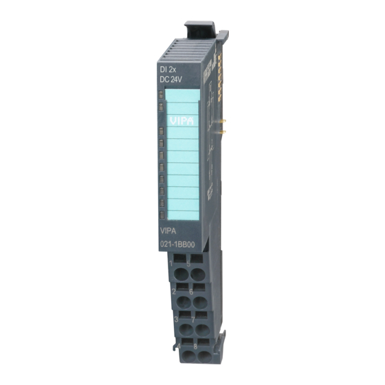
Manual VIPA System SLIO Chapter 2 Digital Input VIPA 021-1BB00 - DI 2xDC 24V The electronic module collects the binary control signals from the process Description level and transmits them isolated to the central bus system. It has 2 channels and their status is monitored via LEDs. - Page 29 Manual VIPA System SLIO Chapter 2 Digital Input For wires with a cross section of 0.08mm up to 2.5mm Pin assignment DC24V Pos. Function Type Description DI 0 Digital input DI 0 DC 24V DC 24V for sensor not connected...
-
Page 30: Vipa 021-1Bd00 - Di 4Xdc 24V
Manual VIPA System SLIO Chapter 2 Digital Input VIPA 021-1BD00 - DI 4xDC 24V The electronic module collects the binary control signals from the process Description level and transmits them isolated to the central bus system. It has 4 channels and their status is monitored via LEDs. - Page 31 Manual VIPA System SLIO Chapter 2 Digital Input For wires with a cross section of 0.08mm up to 2.5mm Pin assignment DC24V Pos. Function Type Description DI 0 Digital input DI 0 DC 24V DC 24V for sensor DI 2...
-
Page 32: Vipa 021-1Bd40 - Di 4Xdc 24V 3 Wire
Manual VIPA System SLIO Chapter 2 Digital Input VIPA 021-1BD40 - DI 4xDC 24V 3 wire The electronic module collects the binary control signals from the process Description level and transmits them isolated to the central bus system. It has 4 channels and their status is monitored via LEDs. - Page 33 Manual VIPA System SLIO Chapter 2 Digital Input For wires with a cross section of 0.08mm up to 2.5mm Pin assignment DC24V Pos. Function Type Description DI 0 Digital input DI 0 DC 24V DC 24V for sensor DI 2...
-
Page 34: Vipa 021-1Bf00 - Di 8Xdc 24V
Manual VIPA System SLIO Chapter 2 Digital Input VIPA 021-1BF00 - DI 8xDC 24V The electronic module collects the binary control signals from the process Description level and transmits them isolated to the central bus system. It has 8 channels and their status is monitored via LEDs. - Page 35 Manual VIPA System SLIO Chapter 2 Digital Input For wires with a cross section of 0.08mm up to 2.5mm Pin assignment DC24V DC24V DC24V Pos. Function Type Description DI 0 Digital input DI 0 DI 2 Digital input DI 2...
- Page 36 Manual VIPA System SLIO Chapter 2 Digital Input 2-10 HB300E - SM - Rev. 09/38...
- Page 37 Page Chapter 3 Digital Output ..............3-1 VIPA 022-1BB00 - DO 2xDC 24V 0.5A ..........3-2 VIPA 022-1BD00 - DO 4xDC 24V 0.5A ..........3-4 VIPA 022-1BF00 - DO 8xDC 24V 0.5A ..........3-6 HB300E - SM - Rev. 09/38...
-
Page 38: Chapter 3 Digital Output
Manual VIPA System SLIO Chapter 3 Digital Output VIPA 022-1BB00 - DO 2xDC 24V 0.5A The electronic module accepts binary control signals from the central bus Description system and transfers them to the process level via outputs. It has 2 channels and their status is monitored via LEDs. - Page 39 Manual VIPA System SLIO Chapter 3 Digital Output For wires with a cross section of 0.08mm up to 2.5mm Pin assignment DC24V Pos. Function Type Description DO 0 Digital output DO 0 DC 24V DC 24V GND for actuator not connected...
-
Page 40: Vipa 022-1Bd00 - Do 4Xdc 24V 0.5A
Manual VIPA System SLIO Chapter 3 Digital Output VIPA 022-1BD00 - DO 4xDC 24V 0.5A The electronic module accepts binary control signals from the central bus Description system and transfers them to the process level via outputs. It has 4 channels and their status is monitored via LEDs. - Page 41 Manual VIPA System SLIO Chapter 3 Digital Output For wires with a cross section of 0.08mm up to 2.5mm Pin assignment DC24V Pos. Function Type Description DO 0 Digital output DO 0 GND for actuator DO 0 DO 2 Digital output DO 2...
-
Page 42: Vipa 022-1Bf00 - Do 8Xdc 24V 0.5A
Manual VIPA System SLIO Chapter 3 Digital Output VIPA 022-1BF00 - DO 8xDC 24V 0.5A The electronic module accepts binary control signals from the central bus Description system and transfers them to the process level via outputs. It has 8 channels and their status is monitored via LEDs. - Page 43 Manual VIPA System SLIO Chapter 3 Digital Output For wires with a cross section of 0.08mm up to 2.5mm Pin assignment DC24V Pos. Function Type Description DO 0 Digital output DO 0 DO 2 Digital output DO 2 DO 4...
- Page 44 Manual VIPA System SLIO Chapter 3 Digital Output HB300E - SM - Rev. 09/38...
-
Page 45: Chapter 4 Analog Input
VIPA 031-1BB30 - AI 2x12Bit 0...10V........... 4-8 VIPA 031-1BB40 - AI 2x12Bit 0(4)...20mA.......... 4-12 VIPA 031-1BD30 - AI 4x12Bit 0...10V..........4-17 VIPA 031-1BD40 - AI 4x12Bit 0(4)...20mA ......... 4-21 VIPA 031-1BD80 - AI 4x16Bit R/RTD ..........4-26 HB300E - SM - Rev. 09/38... -
Page 46: General
Manual VIPA System SLIO Chapter 4 Analog Input General For analog signals you should use screened cables to reduce interference. Cables for analog The cable screening should be grounded at both ends. If there are signals differences in the potential between the cable ends, there may occur a potential compensating current that could disturb the analog signals. -
Page 47: Analog Value
Manual VIPA System SLIO Chapter 4 Analog Input Analog value Analog values are exclusively processed by the CPU in a binary format. For Representation of this the analog module transforms every process signal into a digital value analog values and transfers this as word. -
Page 48: Measuring Ranges
Manual VIPA System SLIO Chapter 4 Analog Input Measuring ranges In the following there are the measuring ranges with function number listed, General which were supported by the corresponding analog module. The here listed formulas allow you to transform an evaluated measuring value (digital value) to a value assigned to the measuring range and vice versa. - Page 49 Manual VIPA System SLIO Chapter 4 Analog Input Measuring range (function number) Measuring value Signal range Range overrange +1000°C +10000 2 wire: PT100 nominal range -200 ... +850°C -2000 ... +8500 (50h) underrange -243°C -2430 overrange +100°C +10000 2 wire: PT1000 nominal range -200 ...
- Page 50 Manual VIPA System SLIO Chapter 4 Analog Input ... continue RTD Measuring range (function number) Measuring value Signal range Range overrange 3 wire: 0 ... 60Ω nominal range 0 ... 32767 0 ... 60Ω (78h) underrange overrange 3 wire: 0 ... 600Ω...
- Page 51 Manual VIPA System SLIO Chapter 4 Analog Input ... continue RTD Measuring range (function number) Measuring value Signal range Range overrange 32511 70.55Ω 2 wire: 0 ... 60Ω nominal range 0 ... 27648 0 ... 60Ω (D0h) underrange overrange 32511 705.5Ω...
-
Page 52: Vipa 031-1Bb30 - Ai 2X12Bit 0
Manual VIPA System SLIO Chapter 4 Analog Input VIPA 031-1BB30 - AI 2x12Bit 0...10V The electronic module has 2 inputs with parameterizable functions. Description The channels of the module are isolated to the backplane bus by means of DC/DC converters. - Page 53 Manual VIPA System SLIO Chapter 4 Analog Input For wires with a cross section of 0.08mm up to 2.5mm Pin assignment DC24V Pos. Function Type Description +AI 0 + Channel 0 -AI 0 Ground Channel 0 not connected not connected...
- Page 54 Manual VIPA System SLIO Chapter 4 Analog Input Byte Meaning Default Diagnostic data Bit 0: error in module Bit 1: reserved Bit 2: external error Bit 3: channel error Bit 4: external auxiliary supply missing Bit 5, 6: reserved Bit 7: wrong parameter in module Bit 3 ...
- Page 55 Manual VIPA System SLIO Chapter 4 Analog Input Data VIPA 031-1BB30 Technical data Number of inputs Power supply DC 24V via power module Input range 0 ... 10V Current consumption 70mA 15mA Internal resistor 100kΩ Limit frequency input filter 1kHz...
-
Page 56: Vipa 031-1Bb40 - Ai 2X12Bit 0(4)
Manual VIPA System SLIO Chapter 4 Analog Input VIPA 031-1BB40 - AI 2x12Bit 0(4)...20mA The electronic module has 2 inputs with parameterizable functions. Description The channels of the module are isolated to the backplane bus by means of DC/DC converters. - Page 57 Manual VIPA System SLIO Chapter 4 Analog Input For wires with a cross section of 0.08mm up to 2.5mm Pin assignment DC24V Pos. Function Type Description +AI 0 + Channel 0 -AI 0 Ground Channel 0 not connected not connected...
- Page 58 Manual VIPA System SLIO Chapter 4 Analog Input Function-number In the following there are the measuring ranges with function-number listed, channel x which were supported by the analog module. With FFh the corresponding channel is deactivated. The formulas listed here allow you to transform an evaluated measuring value (digital value) to a value assigned to the measuring range (analog value) and vice versa.
- Page 59 Manual VIPA System SLIO Chapter 4 Analog Input Byte Meaning Default Diagnostic data Bit 0: error in module Bit 1: reserved Bit 2: external error Bit 3: channel error Bit 4: external auxiliary supply missing Bit 5, 6: reserved Bit 7: wrong parameter in module Bit 3 ...
- Page 60 Manual VIPA System SLIO Chapter 4 Analog Input Data VIPA 031-1BB40 Technical data Number of inputs Power supply DC 24V via power module Input range 0 ... 20mA / 4 ... 20mA Current consumption 70mA 15mA Internal resistor 110kΩ Limit frequency input filter...
-
Page 61: Vipa 031-1Bd30 - Ai 4X12Bit 0
Manual VIPA System SLIO Chapter 4 Analog Input VIPA 031-1BD30 - AI 4x12Bit 0...10V The electronic module has 4 inputs with parameterizable functions. Description The channels of the module are isolated to the backplane bus by means of DC/DC converters. - Page 62 Manual VIPA System SLIO Chapter 4 Analog Input For wires with a cross section of 0.08mm up to 2.5mm Pin assignment DC24V Pos. Function Type Description +AI 0 + Channel 0 -AI 0 Ground Channel 0 +AI 2 + Channel 2...
- Page 63 Manual VIPA System SLIO Chapter 4 Analog Input Byte Meaning Default Diagnostic data Bit 0: error in module Bit 1: reserved Bit 2: external error Bit 3: channel error Bit 4: external auxiliary supply missing Bit 5, 6: reserved Bit 7: wrong parameter in module Bit 3 ...
- Page 64 Manual VIPA System SLIO Chapter 4 Analog Input Data VIPA 031-1BD30 Technical data Number of inputs Power supply DC 24V via power module Input range 0 ... 10V Current consumption 70mA 15mA Internal resistor 100kΩ Limit frequency input filter 1kHz...
-
Page 65: Vipa 031-1Bd40 - Ai 4X12Bit 0(4)
Manual VIPA System SLIO Chapter 4 Analog Input VIPA 031-1BD40 - AI 4x12Bit 0(4)...20mA The electronic module has 4 inputs with parameterizable functions. Description The channels of the module are isolated to the backplane bus by means of DC/DC converters. - Page 66 Manual VIPA System SLIO Chapter 4 Analog Input For wires with a cross section of 0.08mm up to 2.5mm Pin assignment DC24V Pos. Function Type Description +AI 0 + Channel 0 -AI 0 Ground Channel 0 +AI 2 + Channel 2...
- Page 67 Manual VIPA System SLIO Chapter 4 Analog Input Function-number In the following there are the measuring ranges with function-number listed, channel x which were supported by the analog module. With FFh the corresponding channel is deactivated. The formulas listed here allow you to transform an evaluated measuring value (digital value) to a value assigned to the measuring range (analog value) and vice versa.
- Page 68 Manual VIPA System SLIO Chapter 4 Analog Input Byte Meaning Default Diagnostic data Bit 0: error in module Bit 1: reserved Bit 2: external error Bit 3: channel error Bit 4: external auxiliary supply missing Bit 5, 6: reserved Bit 7: wrong parameter in module Bit 3 ...
- Page 69 Manual VIPA System SLIO Chapter 4 Analog Input Data VIPA 031-1BD40 Technical data Number of inputs Power supply DC 24V via power module Input range 0 ... 20mA / 4 ... 20mA Current consumption 70mA 15mA Internal resistor 110kΩ Limit frequency input filter...
-
Page 70: Vipa 031-1Bd80 - Ai 4X16Bit R/Rtd
Manual VIPA System SLIO Chapter 4 Analog Input VIPA 031-1BD80 - AI 4x16Bit R/RTD The electronic module has 4 inputs for resistance measurement with Description parameterizable functions. The channels of the module are isolated to the backplane bus by means of DC/DC converters. - Page 71 Manual VIPA System SLIO Chapter 4 Analog Input For wires with a cross section of 0.08mm up to 2.5mm Pin assignment DC24V Pos. Function Type Description +AI 0 + Channel 0 -AI 0 Ground Channel 0 +AI 2 + Channel 2...
- Page 72 Manual VIPA System SLIO Chapter 4 Analog Input The parameter data may be accessed during runtime with the following Parameter data record sets: Record set Meaning Default Byte Diagnostics Bit 5 ... 0: reserved Bit 6: Diagnostics interrupt (1: activated)
- Page 73 Manual VIPA System SLIO Chapter 4 Analog Input Function option Depending on the Interference frequency suppression for each channel the transducer velocity may be set. Code Velocity/channel at Interference frequency suppression 50Hz 60Hz 324.1 270.5 164.2 137.2 84.2 70.5 44.1 37.2...
- Page 74 Manual VIPA System SLIO Chapter 4 Analog Input Function number Measuring range (Function number) Measuring value Signal range Range overrange +1000°C +10000 2 wire: PT100 nominal range -200 ... +850°C -2000 ... +8500 (50h) underrange -243°C -2430 overrange +100°C +10000...
- Page 75 Manual VIPA System SLIO Chapter 4 Analog Input ... continue Measuring range (Function number) Measuring value Signal range Range overrange 3 wire: 0 ... 60 Ω nominal range 0 ... 60 Ω 0 ... 32767 (78h) underrange overrange 3 wire: 0 ... 600 Ω...
- Page 76 Manual VIPA System SLIO Chapter 4 Analog Input ... continue Measuring range (Function number) Measuring value Signal range Range overrange 70.55 Ω 32511 2 wire: 0 ... 60 Ω nominal range 0 ... 60 Ω 0 ... 27648 (D0h) underrange overrange 705.5 Ω...
- Page 77 Manual VIPA System SLIO Chapter 4 Analog Input Byte Meaning Default Diagnostic data Bit 0: error in module Bit 1: reserved Bit 2: external error Bit 3: channel error Bit 4: external auxiliary supply missing Bit 5, 6: reserved Bit 7: wrong parameter in module Bit 3 ...
- Page 78 Manual VIPA System SLIO Chapter 4 Analog Input Data VIPA 031-1BD80 Technical data Number of inputs 4 (differential) Power supply DC 24V via power module Input range Resistor 0 ... 3000Ω Current consumption 75mA 30mA Internal resistor min. 10MΩ Resolution...
-
Page 79: Chapter 5 Analog Output
General ....................5-2 Analog value ..................5-3 Output ranges ..................5-4 VIPA 032-1BB30 - AO 2x12Bit 0...10V ..........5-5 VIPA 032-1BB40 - AO 2x12Bit 0(4)...20mA.......... 5-9 VIPA 032-1BD30 - AO 4x12Bit 0...10V..........5-14 VIPA 032-1BD40 - AO 4x12Bit 0(4)...20mA........5-19... -
Page 80: General
Manual VIPA System SLIO Chapter 5 Analog Output General You must only use screened cable when you are connecting analog Cabling for signals. These cables reduce the effect of electrical interference. The analog signals screen of the analog signal cable should be grounded at both ends. In situations with different electrical potentials, it is possible that a current will flow to equalize the potential difference. -
Page 81: Analog Value
Manual VIPA System SLIO Chapter 5 Analog Output Analog value The analog values are only processed in binary representation. Hereby the Analog value binary word variable is transformed into an analog process signal and put representation out via the corresponding channel. -
Page 82: Output Ranges
Manual VIPA System SLIO Chapter 5 Analog Output Output ranges In the following there are the output ranges listed with function number, General which were supported by the corresponding analog module The here listed formulas allow you to transform a value (digital value) to an analog value and vice versa. -
Page 83: Vipa 032-1Bb30 - Ao 2X12Bit 0
Manual VIPA System SLIO Chapter 5 Analog Output VIPA 032-1BB30 - AO 2x12Bit 0...10V The electronic module has 2 outputs with parameterizable functions. Description The channels of the module are isolated to the backplane bus by means of DC/DC converters. - Page 84 Manual VIPA System SLIO Chapter 5 Analog Output For wires with a cross section of 0.08mm up to 2.5mm Pin assignment DC24V Pos. Function Type Description AO 0 Channel 0 AGND Ground channels not connected not connected AO 1 Channel 1...
- Page 85 Manual VIPA System SLIO Chapter 5 Analog Output Byte Meaning Default Diagnostic data Bit 0: error in module Bit 1: reserved Bit 2: external error Bit 3: channel error Bit 4: external auxiliary supply missing Bit 5, 6: reserved Bit 7: wrong parameter in module Bit 3 ...
- Page 86 Manual VIPA System SLIO Chapter 5 Analog Output Data VIPA 032-1BB30 Technical data Number of inputs 2 (single-ended) Power supply DC 24V via power module Input range 0 ... 10V Current consumption 80mA 35mA Burden min. 5kΩ (short-circuit proof) Accuracy 0.2%...
-
Page 87: Vipa 032-1Bb40 - Ao 2X12Bit 0(4)
Manual VIPA System SLIO Chapter 5 Analog Output VIPA 032-1BB40 - AO 2x12Bit 0(4)...20mA The electronic module has 2 outputs with parameterizable functions. Description The channels of the module are isolated to the backplane bus by means of DC/DC converters. - Page 88 Manual VIPA System SLIO Chapter 5 Analog Output For wires with a cross section of 0.08mm up to 2.5mm Pin assignment DC24V Pos. Function Type Description AO 0 Channel 0 AGND Ground channels not connected not connected AO 1 Channel 1...
- Page 89 Manual VIPA System SLIO Chapter 5 Analog Output Function-number In the following there are the measuring ranges with function-number listed, channel x which were supported by the analog module. With FFh the corresponding channel is deactivated. The formulas listed here allow you to transform an evaluated measuring value (digital value) to a value assigned to the measuring range (analog value) and vice versa.
- Page 90 Manual VIPA System SLIO Chapter 5 Analog Output Byte Meaning Default Diagnostic data Bit 0: error in module Bit 1: reserved Bit 2: external error Bit 3: channel error Bit 4: external auxiliary supply missing Bit 5, 6: reserved Bit 7: wrong parameter in module Bit 3 ...
- Page 91 Manual VIPA System SLIO Chapter 5 Analog Output Data VIPA 032-1BB40 Technical data Number of inputs 2 (single-ended) Power supply DC 24V via power module Input range 0...20mA / 4...20mA Current consumption 80mA 15mA without load Burden max. 350Ω Accuracy 0 ...
-
Page 92: Vipa 032-1Bd30 - Ao 4X12Bit 0
Manual VIPA System SLIO Chapter 5 Analog Output VIPA 032-1BD30 - AO 4x12Bit 0...10V The electronic module has 4 outputs with parameterizable functions. Description The channels of the module are isolated to the backplane bus by means of DC/DC converters. - Page 93 Manual VIPA System SLIO Chapter 5 Analog Output For wires with a cross section of 0.08mm up to 2.5mm Pin assignment DC24V Pos. Function Type Description AO 0 Channel 0 AGND Ground channels AO 2 Channel 2 AGND Ground channels...
- Page 94 Manual VIPA System SLIO Chapter 5 Analog Output Function-number In the following there are the measuring ranges with function-number listed, channel x which were supported by the analog module. With FFh the corresponding channel is deactivated. The formulas listed here allow you to transform an evaluated measuring value (digital value) to a value assigned to the measuring range (analog value) and vice versa.
- Page 95 Manual VIPA System SLIO Chapter 5 Analog Output Byte Meaning Default Diagnostic data Bit 0: error in module Bit 1: reserved Bit 2: external error Bit 3: channel error Bit 4: external auxiliary supply missing Bit 5, 6: reserved Bit 7: wrong parameter in module Bit 3 ...
- Page 96 Manual VIPA System SLIO Chapter 5 Analog Output Data VIPA 032-1BD30 Technical data Number of inputs 4 (single-ended) Power supply DC 24V via power module Input range 0 ... 10V Current consumption 80mA 35mA Burden min. 5kΩ (short-circuit proof) Accuracy 0.2%...
-
Page 97: Vipa 032-1Bd40 - Ao 4X12Bit 0(4)
Manual VIPA System SLIO Chapter 5 Analog Output VIPA 032-1BD40 - AO 4x12Bit 0(4)...20mA The electronic module has 4 outputs with parameterizable functions. Description The channels of the module are isolated to the backplane bus by means of DC/DC converters. - Page 98 Manual VIPA System SLIO Chapter 5 Analog Output For wires with a cross section of 0.08mm up to 2.5mm Pin assignment DC24V Pos. Function Type Description AO 0 Channel 0 AGND Ground channels AO 2 Channel 2 AGND Ground channels...
- Page 99 Manual VIPA System SLIO Chapter 5 Analog Output Function-number In the following there are the measuring ranges with function-number listed, channel x which were supported by the analog module. With FFh the corresponding channel is deactivated. The formulas listed here allow you to transform an evaluated measuring value (digital value) to a value assigned to the measuring range (analog value) and vice versa.
- Page 100 Manual VIPA System SLIO Chapter 5 Analog Output Byte Meaning Default Diagnostic data Bit 0: error in module Bit 1: reserved Bit 2: external error Bit 3: channel error Bit 4: external auxiliary supply missing Bit 5, 6: reserved Bit 7: wrong parameter in module Bit 3 ...
- Page 101 Manual VIPA System SLIO Chapter 5 Analog Output Data VIPA 032-1BD40 Technical data Number of inputs 4 (single-ended) Power supply DC 24V via power module Input range 0...20mA / 4...20mA Current consumption 80mA 15mA without load Burden max. 350Ω Accuracy 0 ...
- Page 102 Manual VIPA System SLIO Chapter 5 Analog Output 5-24 HB300E - SM - Rev. 09/38...
Need help?
Do you have a question about the 021-1BB00 and is the answer not in the manual?
Questions and answers