Table of Contents
Advertisement
This manual is part of the documentation package
with order number VIPA HB140E_CPU_SC and relevant for:
Product
Order number
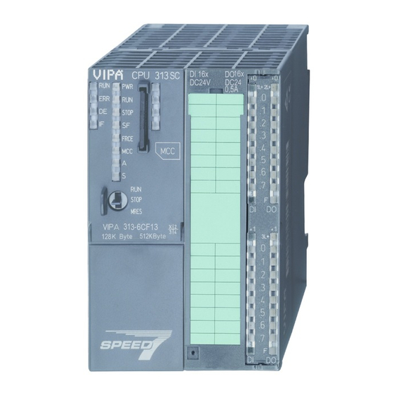
CPU 313SC/DPM
VIPA 313-6CF03
Manual
VIPA System 300S
SPEED7 - CPU SC
313-6CF03
Order No.: VIPA HB140E_CPU_SC
Reference: RE_313-6CF03
Rev. 07/45
as of state:
CPU HW
CPU FW
01
V328
DPM FW
V312
Advertisement
Table of Contents


Need help?
Do you have a question about the System 300S SPEED7 CPU 313SC/DPM and is the answer not in the manual?
Questions and answers