
Related Manuals for VIPA System SLIO IM 053DN


Summary of Contents for VIPA System SLIO IM 053DN
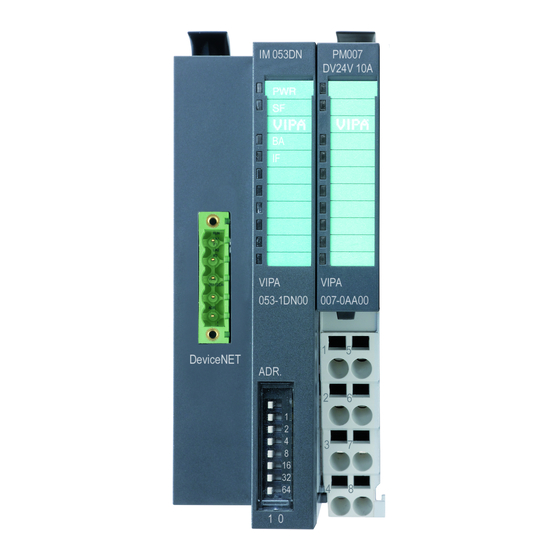
- Page 1 VIPA System SLIO IM 053DN IM | 053-1DN00 | Manual HB300 | IM | 053-1DN00 | GB | 15-33...
- Page 2 VIPA GmbH Ohmstr. 4 91074 Herzogenaurach Telephone: +49 9132 744-0 Fax: +49 9132 744-1864 Email: info@vipa.com Internet: www.vipa.com 053-1DN00_000_IM 053DN,2,GB - © 2015...
-
Page 3: Table Of Contents
VIPA System SLIO IM 053DN Table of contents Table of contents General..................4 1.1 Copyright © VIPA GmbH ........... 4 1.2 About this manual.............. 5 1.3 Safety information.............. 6 Basics and Assembly.............. 8 2.1 Safety information for users..........8 2.2 System conception............. 9 2.3 Dimensions.............. -
Page 4: General
General 1.1 Copyright © VIPA GmbH All Rights Reserved This document contains proprietary information of VIPA and is not to be disclosed or used except in accordance with applicable agree- ments. This material is protected by the copyright laws. It may not be repro-... -
Page 5: About This Manual
Tel.: +49 9132 744-1150 (Hotline) EMail: support@vipa.de 1.2 About this manual Objective and contents This manual describes the IM 053-1DN00 of the System SLIO from VIPA. It contains a description of the structure, project engineering and deployment. Product Order number as of state:... -
Page 6: Safety Information
General VIPA System SLIO IM 053DN Safety information Guide to the document The following guides are available in the manual: An overall table of contents at the beginning of the manual References with page numbers Availability The manual is available in:... - Page 7 VIPA System SLIO IM 053DN General Safety information CAUTION! The following conditions must be met before using or commissioning the components described in this manual: – Hardware modifications to the process control system should only be carried out when the system has been disconnected from power! –...
-
Page 8: Basics And Assembly
Basics and Assembly 2.1 Safety information for users Handling of electro- VIPA modules make use of highly integrated components in MOS- static sensitive modules Technology. These components are extremely sensitive to over-vol- tages that can occur during electrostatic discharges. The following symbol is attached to modules that can be destroyed by electrostatic discharges. -
Page 9: System Conception
Components CPU (head module) Bus coupler (head module) Periphery modules Power modules Accessories CAUTION! Only modules of VIPA may be combined. A mixed opera- tion with third-party modules is not allowed! HB300 | IM | 053-1DN00 | GB | 15-33... - Page 10 Basics and Assembly VIPA System SLIO IM 053DN System conception With a CPU, CPU electronic and power module are integrated to one casing. As head module via the integrated power module for power supply the CPU electronic is supplied as well as the electronic of the connected periphery modules.
- Page 11 VIPA System SLIO IM 053DN Basics and Assembly System conception Terminal module The terminal module serves to carry the electronic module, contains the backplane bus with power supply for the electronic, the DC 24V power section supply and the staircase-shaped terminal for wiring.
- Page 12 Basics and Assembly VIPA System SLIO IM 053DN System conception (1) DC 24V for power section supply I/O area (max. 10A) (2) DC 24V for electronic power supply bus coupler and I/O area (3) DC 24V for power section supply I/O area (max. 4A)
-
Page 13: Dimensions
Coding pins There is the possibility to fix the assignment of electronic and terminal module. Here coding pins (order number 000-0AC00) from VIPA can be used. The coding pin consists of a coding jack and a coding plug. By combining electronic and terminal module with coding pin, the coding jack remains in the electronic module and the coding plug in the terminal module. - Page 14 Basics and Assembly VIPA System SLIO IM 053DN Dimensions Dimensions bus cou- pler Dimensions periphery module Dimensions electronic module Dimensions in mm HB300 | IM | 053-1DN00 | GB | 15-33...
-
Page 15: Installation
Coding There is the possibility to fix the assignment of electronic and terminal module. Here coding pins (order number 000-0AC00) from VIPA can be used. The coding pin consists of a coding jack and a coding plug. By combining electronic and terminal module with coding pin, the coding jack remains in the electronic module and the coding plug in the terminal module. - Page 16 Even with an existing coding on the terminal module, you can plug an electronic module without coding. The user is responsible for the correct usage of the coding pins. VIPA assumes no liability for incorrectly attached electronic modules or for damages which arise due to incorrect...
- Page 17 VIPA System SLIO IM 053DN Basics and Assembly Installation Mounting rail Mount the mounting rail! Please consider that a clearance from the middle of the mounting rail of at least 80mm above and 60mm below, respectively 80mm by deployment of shield bus carriers, exist.
- Page 18 Basics and Assembly VIPA System SLIO IM 053DN Installation Mounting periphery modules Mount the periphery modules you want. Mounting the bus cover After mounting the whole system, to protect the backplane bus connectors at the last module you have to mount the bus cover, now.
-
Page 19: Demounting And Module Exchange
VIPA System SLIO IM 053DN Basics and Assembly Demounting and module exchange Mounting shield bus carrier The shield bus carrier (available as accessory) serves to carry the shield bus to connect cable shields. The shield bus carrier is mounted underneath the terminal of the terminal module. With a flat mounting rail for adaption to a flat mounting rail you may remove the spacer of the shield bus carrier. - Page 20 Basics and Assembly VIPA System SLIO IM 053DN Demounting and module exchange Exchange of a module Ä Chapter 2.6 ‘Wiring’ on page 23. Remove if exists the wiring. Press the unlocking lever at the lower side of the just mounted right module and pull it forward.
- Page 21 VIPA System SLIO IM 053DN Basics and Assembly Demounting and module exchange CAUTION! Bus interface and power module of a head module may not be separated! Here you may only exchange the electronic module! Remove if exists the wiring of the head module.
- Page 22 Basics and Assembly VIPA System SLIO IM 053DN Demounting and module exchange Exchange of a module group Ä Chapter 2.6 Remove if exists the wiring of the module group. ‘Wiring’ on page 23. Press the unlocking lever at the lower side of the just mounted right module of the module group and pull it forward.
-
Page 23: Wiring
VIPA System SLIO IM 053DN Basics and Assembly Wiring Turn all the locking lever downward again. Plug again the electronic module, which you have removed before. 2.6 Wiring Connectors Terminals with spring clamp technology are used for wiring. The spring clamp technology allows quick and easy connection of your signal and supply lines. - Page 24 Basics and Assembly VIPA System SLIO IM 053DN Wiring Standard wiring (1) DC 24V for power section supply I/O area (max 10A) (2) DC 24V for electronic power supply bus coupler and I/O area PM - Power module For wires with a core cross-section of 0.08mm up to 1.5mm...
- Page 25 Deployment of the If the 10A for the power section supply is no longer sufficient, you power modules may use the power module from VIPA with the order number 007-1AB00. So you have also the possibility to define isolated groups.
- Page 26 Basics and Assembly VIPA System SLIO IM 053DN Wiring Power module 007-1AB10 (1) DC 24V for power section supply I/O area (max. 10A) (2) DC 24V for electronic power supply bus coupler and I/O area (3) DC 24V for power section supply I/O area (max. 4A)
-
Page 27: Trouble Shooting - Leds
VIPA System SLIO IM 053DN Basics and Assembly Installation guidelines 2.7 Trouble shooting - LEDs General Each module has the LEDs RUN and MF on its front side. Errors or incorrect modules may be located by means of these LEDs. - Page 28 The components of VIPA are developed for the deployment in indus- trial environments and meets high demands on the EMC. Neverthe- less you should project an EMC planning before installing the compo- nents and take conceivable interference causes into account.
- Page 29 VIPA System SLIO IM 053DN Basics and Assembly Installation guidelines In special use cases you should appoint special EMC actions. – Consider to wire all inductivities with erase links. – Please consider luminescent lamps can influence signal lines. Create a homogeneous reference potential and ground all elec- trical operating supplies when possible.
-
Page 30: General Data
Basics and Assembly VIPA System SLIO IM 053DN General data 2.9 General data Conformity and approval Conformity 2006/95/EG Low-voltage directive 2004/108/EG EMC directive Approval UL 508 Approval for USA and Canada others RoHS 2011/65/EU Product is lead-free; Restriction of the use of... - Page 31 VIPA System SLIO IM 053DN Basics and Assembly General data Mounting conditions Mounting place In the control cabinet Mounting position Horizontal and vertical Standard Comment Emitted interfer- EN 61000-6-4 Class A (Industrial area) ence Noise immunity EN 61000-6-2 Industrial area...
-
Page 32: Hardware Description
Hardware description VIPA System SLIO IM 053DN Properties Hardware description 3.1 Properties Features The interface module 053-1DN00 is a head station for the System SLIO with an DeviceNet interface. With the DeviceNet interface the input data can be read and output data written, which parameteriza- tion system, as well as updates be accomplished. -
Page 33: Structure
VIPA System SLIO IM 053DN Hardware description Structure > Interfaces 3.2 Structure 053-1DN00 Locking lever terminal module Labeling strip bus interface LED status indication bus interface Labelling strip power module LED status indication power module Backplane bus DC 24V power section supply... -
Page 34: Address Switch
The shield is to be connected to pin 3 (DR) and grounded at one suited place within its network. You receive a suited plug from VIPA with the order number VIPA 000-0DN00. Members of the bus may optionally be supplied by an external DC 24V power supply. - Page 35 VIPA System SLIO IM 053DN Hardware description Structure > Address switch Changes of the transfer rate respectively of the DeviceNet address were only recognized after PowerON or an auto- matic reset. Changes during the normal operation are not recognized! Settings...
-
Page 36: Leds
Hardware description VIPA System SLIO IM 053DN Structure > LEDs Update mode for firmware update Description Setting Configuration Update mode 3.2.3 LEDs LEDs power module Description green green ● ○ Power section supply OK ● ● ○ Electronic section supply OK ●... -
Page 37: Technical Data
VIPA System SLIO IM 053DN Hardware description Technical data 3.3 Technical data Order no. 053-1DN00 Type IM 053DN Module ID Technical data power supply Power supply (rated value) DC 24 V Power supply (permitted range) DC 20.4...28.8 V Reverse polarity protection ü... - Page 38 Hardware description VIPA System SLIO IM 053DN Technical data Order no. 053-1DN00 Number of participants, max. Node addresses 0 - 63 Transmission speed, min. 125 kbit/s Transmission speed, max. 500 kbit/s Address range inputs, max. 256 Byte Address range outputs, max.
-
Page 39: Deployment
VIPA System SLIO IM 053DN Deployment Basics DeviceNet Deployment 4.1 Basics DeviceNet General DeviceNet is an open low-end network that is based upon the phys- ical properties of CAN bus. The bus is also used to supply the devices with the required DC 24V power. You can use DeviceNet to... -
Page 40: Accessing The System Slio
ID address. Every DeviceNet device has addressing facilities. EDS file: From VIPA there are EDS (Electronic Data Sheet) files for the DeviceNet coupler available. These files may either be found on the supplied storage media or at the download area of www.vipa.com... - Page 41 VIPA System SLIO IM 053DN Deployment Accessing the System SLIO Information concerning the allocation of these areas may be found in the description of the corresponding System SLIO module. Please consider the System SLIO power and clamp modules do not have any module ID. These may not be recognized by the DeviceNet coupler and so are not listed and considered during slot allocation.
-
Page 42: Accessing The I/O Area
Accessing the System SLIO > Accessing the I/O area EDS file From VIPA you may receive an appropriate EDS file (Electronic Data Sheet) for your DeviceNet coupler, which depends on your configura- tion (number of modules). These files may either be found on the sup- plied storage media or at the download area of www.vipa.com. -
Page 43: Accessing Parameter Data
VIPA System SLIO IM 053DN Deployment Accessing the System SLIO > Accessing parameter data Activate the System SLIO DeviceNet coupler IM 053DN in the scan list. Start the DeviceNet scanner. ð When the DeviceNet scanner has been configured, the input and output modules are accessible via the configured addresses. -
Page 44: Accessing Diagnostics Data
Deployment VIPA System SLIO IM 053DN Accessing the System SLIO > Accessing diagnostics data As soon as the parameter data do not fit to the sequence of the modules on the System SLIO bus, the DeviceNet coupler goes to an error state and signals this with its status LEDs. -
Page 45: Transfer Rate And Devicenet Address
VIPA System SLIO IM 053DN Deployment Transfer rate and DeviceNet address > Setting the transfer rate System SLIO module - Class Code: Slot 1: 101 (65h), Slot 2: 102 (66h), ... , Slot 64: 164 (A4h) No. Name Information Format... -
Page 46: Setting The Devicenet Address
Deployment VIPA System SLIO IM 053DN Transfer rate and DeviceNet address > Setting the DeviceNet address Switch on the power supply. ð The preset transfer rate is stored in the EEPROM. Your DeviceNet coupler now uses this transfer rate. LED indication (RD, SF): With an successful storage the RD LED (green) gets on. -
Page 47: Status Indication - Diagnostics
VIPA System SLIO IM 053DN Deployment Status indication - Diagnostics Pos. Description Example Setting Description Configuration 1+2+32=35 Address: 35 = 16 = 32 Auto configuration 0 / 1 Auto - On start-up with Auto configuration = "1" the current configu-... - Page 48 Deployment VIPA System SLIO IM 053DN Status indication - Diagnostics RD BA Meaning ● ○ Error field bus Field bus address just exists Communication error on the field bus ● Inactivity connection disconnected due to inactivity System SLIO bus ready, outputs inactive ●...
Need help?
Do you have a question about the System SLIO IM 053DN and is the answer not in the manual?
Questions and answers