
Related Manuals for VIPA 2 SLIO System IM 053DP


Summary of Contents for VIPA 2 SLIO System IM 053DP
- Page 1 VIPA System SLIO IM | 053-1DP00 | Manual HB300E_IM | RE_053-1DP00 | Rev. 11/03 January 2011...
- Page 2 Copyright © VIPA GmbH. All Rights Reserved. This document contains proprietary information of VIPA and is not to be disclosed or used except in accordance with applicable agreements. This material is protected by the copyright laws. It may not be reproduced, distributed, or altered in any fashion by any entity (either internal or external to VIPA), except in accordance with applicable agreements, contracts or licensing, without the express written consent of VIPA and the business management owner of the material.
-
Page 3: Table Of Contents
Manual VIPA System SLIO Contents Contents About this manual ..................1 Safety information ..................2 Chapter 1 Basics and Assembly ............. 1-1 Safety Information for Users..............1-2 System conception ................1-3 Dimensions ..................1-6 Installation .................... 1-7 Wiring....................1-11 Trouble shooting - LEDs..............1-14 Installation guidelines ................. - Page 4 Contents Manual VIPA System SLIO HB300E - IM - RE_053-1DP00 - Rev. 11/03...
-
Page 5: About This Manual
Overview Chapter 1: Basics and Assembly The focus of this chapter is on the introduction of the VIPA System SLIO. Here you will find the information required to assemble and wire a controller system consisting of System SLIO components. Besides the dimensions the general technical data of System SLIO will be found. - Page 6 About this manual Manual VIPA System SLIO This manual describes the IM 053-1DP00 of the System SLIO from VIPA. Objective and It contains a description of the structure, project engineering and contents deployment. This manual is part of the documentation package...
-
Page 7: Safety Information
Manual VIPA System SLIO Safety information Safety information Applications The System SLIO is constructed and produced for: conforming with • communication and process control specifications • general control and automation applications • industrial applications • operation within the environmental conditions specified in the technical data •... - Page 8 Safety information Manual VIPA System SLIO HB300E - IM - RE_053-1DP00 - Rev. 11/03...
-
Page 9: Chapter 1 Basics And Assembly
Chapter 1 Basics and Assembly Overview The focus of this chapter is on the introduction of the VIPA System SLIO. Here you will find the information required to assemble and wire a controller system consisting of System SLIO components. Besides the dimensions the general technical data of System SLIO will be found. -
Page 10: Safety Information For Users
Chapter 1 Basics and Assembly Manual VIPA System SLIO Safety Information for Users Handling of VIPA modules make use of highly integrated components in MOS- Technology. These components are extremely sensitive to over-voltages electrostatic that can occur during electrostatic discharges. -
Page 11: System Conception
Manual VIPA System SLIO Chapter 1 Basics and Assembly System conception Overview System SLIO is a modular automation system for assembly on a 35mm mounting rail. By means of the peripheral modules with 2, 4 or 8 channels this system may properly be adapted matching to your automation tasks. - Page 12 Chapter 1 Basics and Assembly Manual VIPA System SLIO Each periphery module consists of a terminal and an electronic module. Periphery modules Terminal module Electronic module Terminal module The terminal module serves to carry the electronic module, contains the backplane bus with power supply for the electronic, the DC 24V power section supply and the staircase-shaped terminal for wiring.
- Page 13 Manual VIPA System SLIO Chapter 1 Basics and Assembly Accessories Shield bus carrier The shield bus carrier serves to carry the shield bus (10mm x 3mm) to connect cable shields. Shield bus carriers, shield bus and shield fixings are not in the scope of delivery.
-
Page 14: Dimensions
Chapter 1 Basics and Assembly Manual VIPA System SLIO Dimensions Dimensions bus coupler 76.5 48.5 Dimensions periphery module 76.5 12.9 Dimensions electronic module 12.9 Dimensions in mm HB300E - IM - RE_053-1DP00 - Rev. 11/03... -
Page 15: Installation
Manual VIPA System SLIO Chapter 1 Basics and Assembly Installation Functional principle Mounting There is a locking lever at the top side of the terminal module. For terminal module mounting and de-mounting this locking lever is to turn upwards until this engages audible. - Page 16 Chapter 1 Basics and Assembly Manual VIPA System SLIO The modules were directly be mounted to the mounting rail and so Mounting connected to the backplane bus and the power supply for the electronic Proceeding and power section. Up to 64 modules may be mounted. Please consider here that the sum current of the electronic power supply does not exceed the maximum value of 3A.
- Page 17 Manual VIPA System SLIO Chapter 1 Basics and Assembly • Mounting Mount the periphery modules you want. periphery module Clack • After mounting the whole system, to protect the backplane bus Mounting the bus cover connectors at the last module you have to mount the bus cover, now.
- Page 18 Chapter 1 Basics and Assembly Manual VIPA System SLIO With the mounting of a SLIO module respectively of a group of SLIO Mounting modules between two modules for mounting reasons you have always to between 2 remove the electronic module of the just mounted right module. After that it modules may be plugged again.
-
Page 19: Wiring
Manual VIPA System SLIO Chapter 1 Basics and Assembly Wiring Standard wiring SysDC5V max. 3A DC24V max. 10A DC24V DC24V (1) DC 24V for power section supply I/O area (max 10A) (2) DC 24V for electronic power supply bus coupler and I/O area... - Page 20 If the 10A for the power section supply is no longer sufficient, you may use Deployment of the the power module from VIPA with the order number 007-1AB00. So you power modules have also the possibility to define isolated groups.
- Page 21 Manual VIPA System SLIO Chapter 1 Basics and Assembly To attach the shield the mounting of shield bus carriers are necessary. Shield attachment The shield bus carrier (available as accessory) serves to carry the shield bus to connect cable shields.
-
Page 22: Trouble Shooting - Leds
Chapter 1 Basics and Assembly Manual VIPA System SLIO Trouble shooting - LEDs General Each module has the LEDs RUN and MF on its front side. Errors or incorrect modules may be located by means of these LEDs. In the following illustrations flashing LEDs are marked by ☼. -
Page 23: Installation Guidelines
Manual VIPA System SLIO Chapter 1 Basics and Assembly Installation guidelines General The installation guidelines contain information about the interference free deployment of System SLIO. There is the description of the ways, interference may occur in your control, how you can make sure the electromagnetic digestibility (EMC), and how you manage the isolation. - Page 24 Chapter 1 Basics and Assembly Manual VIPA System SLIO In the most times it is enough to take care of some elementary rules to Basic rules for guarantee the EMC. Please regard the following basic rules when installing your PLC.
- Page 25 Manual VIPA System SLIO Chapter 1 Basics and Assembly Electrical, magnetically and electromagnetic interference fields are Isolation of weakened by means of an isolation, one talks of absorption. conductors Via the isolation rail, that is connected conductive with the rack, interference currents are shunt via cable isolation to the ground.
-
Page 26: General Data
Chapter 1 Basics and Assembly Manual VIPA System SLIO General data Conformity and approval Conformity 2006/95/EG Low-voltage directive Approval UL 508 Approval for USA and Canada others RoHs Product is unleaded Protection of persons and device protection Type of protection... -
Page 27: Chapter 2 Hardware Description
Manual VIPA System SLIO Chapter 2 Hardware description Chapter 2 Hardware description Overview Here the hardware components of the IM 053-1DP00 are more described. You will find the technical data at the end of this chapter. Content Topic Page Chapter 2 Hardware description ............. -
Page 28: Properties
Chapter 2 Hardware description Manual VIPA System SLIO Properties • Field bus: PROFIBUS (DP-V0, DP-V1) Features • PROFIBUS DP slave for max. 64 periphery modules • Max. 244byte input and 244byte output data • Supports every PROFIBUS transfer rates • Integrated DC 24V power supply for power and electronic section supply of the periphery modules. -
Page 29: Structure
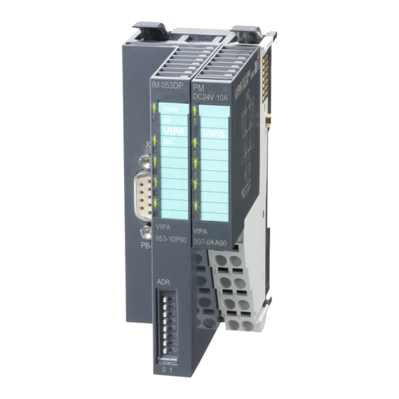
Manual VIPA System SLIO Chapter 2 Hardware description Structure 053-1DP00 Locking lever terminal module Labeling strip bus interface LED status indication bus interface Labeling strip power module LED status indication power module Backplane bus DC 24V power section supply Power module... - Page 30 Chapter 2 Hardware description Manual VIPA System SLIO For wires with a core cross-section of 0.08mm up to 1.5mm Terminal DC24V DC24V DC24V Pos. Function Type Description not connected DC 24V DC 24V for power section supply GND for power section supply...
- Page 31 Manual VIPA System SLIO Chapter 2 Hardware description Connecting the bus The following picture illustrates the terminating resistors of the respective start and end station. Master Slave Slave RxD/TxD-P(B) RxD/TxD-P(B) RxD/TxD-P(B) RxD/TxD-N(A) RxD/TxD-N(A) RxD/TxD-N(A) Shield Shield Shield Note! Please consider to terminate the last participants on the bus at both ends by activating the terminating resistor.
-
Page 32: Technical Data
Chapter 2 Hardware description Manual VIPA System SLIO Technical data Order number 053-1DP00 Type IM 053DP Module ID Technical data power supply Power supply (rated value) DC 24 V Power supply (permitted range) DC 20.4...28.8 V Reverse polarity protection Current consumption (no-load operation) Current consumption (rated value) 0.9 A... -
Page 33: Chapter 3 Deployment
Manual VIPA System SLIO Chapter 3 Deployment Chapter 3 Deployment Overview This chapter describes the usage of the IM 053-1DP00 with PROFIBUS. After a short introduction you may find here every information about assembly and project engineering. The chapter closes with the description of the PROFIBUS installation guidelines and the diagnostic functions. -
Page 34: Basics
Chapter 3 Deployment Manual VIPA System SLIO Basics General PROFIBUS is an international standard applicable to an open field bus for building, manufacturing and process automation. PROFIBUS defines the technical and functional characteristics of a serial field bus system that can be used to create a low (sensor-/actuator level) or medium (process level) performance network of programmable logic controllers. - Page 35 Slave devices A PROFIBUS slave acquires data from peripheral equipment, sensors, actuators and transducers. The VIPA PROFIBUS couplers are modular slave devices that transfer data between the periphery and the high-level master. In accordance with the PROFIBUS standards these devices have no bus access rights.
- Page 36 Chapter 3 Deployment Manual VIPA System SLIO The bus transfer protocol provides two alternatives for the access to the Communication bus: Master with Master communication is also referred to as token-passing procedure. The master token-passing procedure guarantees the accessibility of the bus. The permission to access the bus is transferred between individual devices in the form of a "token".
- Page 37 Manual VIPA System SLIO Chapter 3 Deployment DP-V0 provides the basic functionality of DP, including cycle data Function exchange as well as station diagnostic, module diagnostic and channel- cyclic data specific diagnostic. communication Data is transferred cyclically between the DP master and the DP slave by (DP-V0) means of transmit and receive buffers.
- Page 38 Chapter 3 Deployment Manual VIPA System SLIO The key feature of version DP-V1 is the extended function for acyclic data Function communication. This forms the requirement for parameterization and acyclic data calibration of the field devices over the bus during runtime and for the communication introduction of confirmed alarm messages.
- Page 39 Manual VIPA System SLIO Chapter 3 Deployment Addressing with When addressing data, PROFIBUS assumes that the physical structure of Slot and Index the slaves is modular or it can be structured internally in logical functional units, so-called modules. This model is also used in the basic DP functions...
- Page 40 There are the following handling blocks available for CPUs, programmable with Siemens STEP7, like SPEED7 CPUs from VIPA: SFB 52 Read record set from a DP slave...
- Page 41 System SLIO between 1 and 125. For every PROFIBUS slave from VIPA there is a GSD file available. This GSD- file file may either be found on the supplied storage media or at the download area of www.vipa.de.
-
Page 42: Accessing The System Slio
GSD file To configure the slave connections in your own configuration tool, you’ve got all the information about your VIPA-modules in form of an electronic data sheet file. Install this GSD file in you configuration tool. This file may either be found on the supplied storage media or at the download area of www.vipa.de. - Page 43 Manual VIPA System SLIO Chapter 3 Deployment At PROFIBUS the input respectively output area is automatically embedded Accessing to the corresponding address area of the master system. I/O area There is the possibility to set parameter data of the corresponding modules Accessing by means of the GSD file via hardware configuration.
- Page 44 Chapter 3 Deployment Manual VIPA System SLIO Structure Byte Bit 7 ... Bit 0 diagnostics data Bit 0: Module malfunction, i.e. a problem has been detected Bit 1: Internal error in the module Bit 2: External error - module no longer addressable...
-
Page 45: Project Engineering
PROFIBUS DP > Additional Field devices > I/O > VIPA_SLIO GSD- file For every PROFIBUS slave from VIPA there is a GSD file available. This file may either be found on the supplied storage media or at the download area of www.vipa.de. - Page 46 Chapter 3 Deployment Manual VIPA System SLIO Parameter data At usage of the IM 053-1DP00 (DP-V0) you have the following parameter IM 053-1DP00 data: DP-V0 Byte Bit 7 ... Bit 0 Default Bit 2 ... 0: 0 (fix) Bit 3: 0 = WD-Timebase 10ms...
- Page 47 Manual VIPA System SLIO Chapter 3 Deployment Parameter data At usage of the IM 053-1DP00 (DP-V1) you have the following parameter IM 053-1DP00 data: DP-V1 Byte Bit 7 ... Bit 0 Default Bit 2 ... 0: 0 (fix) Bit 3: 0 = WD-Timebase 10ms...
-
Page 48: Dp-V1 Services
DP-V1 communication. More detailed information about this may be found in the description of your master system. There are the following handling blocks available for CPUs, programmable with Siemens STEP7, like SPEED7 CPUs from VIPA: SFB 52 Read record set from a DP slave... - Page 49 Manual VIPA System SLIO Chapter 3 Deployment Data of the To access the function modules with the Siemens SIMATIC Manager the function modules module address, which can be set by properties, is used as ID. Using the following record set no. as Index you get access for reading (R) res.
-
Page 50: Dp-V1 - I&M Data
Chapter 3 Deployment Manual VIPA System SLIO DP-V1 - I&M data Overview Identification and maintenance data (I&M) are stored information in a module which support you at: • check of the system configuration • discover of hardware changes • remove errors in a system Identification data (I data) are information of the module e.g. - Page 51 Manual VIPA System SLIO Chapter 3 Deployment ... continue I&M data Access Preset Explanation SOFTWARE_REVISION read (4byte) Firmware version Firmware version of the module. Vxyz An increase of the firmware version also increases the hardware revision REVISION_COUNTER read (2byte) 0000h...
-
Page 52: Profibus Installation Guidelines
Chapter 3 Deployment Manual VIPA System SLIO PROFIBUS installation guidelines PROFIBUS in • A PROFIBUS DP network may only be built up in linear structure. general • PROFIBUS DP consists of minimum one segment with at least one master and one slave. - Page 53 In systems with more than two stations all partners are wired in parallel. bus connector For that purpose, the bus cable must be feed-through uninterrupted. Via the order number VIPA 972-0DP10 you may order the bus connector "EasyConn". This is a bus connector with switchable terminating resistor and integrated bus diagnostic.
- Page 54 A (EN50170). Starting with release 5 you also can use highly flexible bus cable: Lapp Kabel order no.: 2170222, 2170822, 2170322. With the order no. 905-6AA00 VIPA offers the "EasyStrip" de-isolating tool that makes the connection of the EasyConn much easier.
-
Page 55: Diagnostic Functions
Manual VIPA System SLIO Chapter 3 Deployment Diagnostic functions Structure of the PROFIBUS DP provides an extensive set of diagnostic functions for quick 053-1DP00 error localization. Diagnostic messages are transferred via the bus and diagnostic data collected by the master. - Page 56 Chapter 3 Deployment Manual VIPA System SLIO Identifier-related Via the Identifier-related diagnostic you gain information at which plug-in diagnostic location (module) an error has occurred. More detailed information about the error is available via the Module state and the channel-related diagnostic.
- Page 57 Manual VIPA System SLIO Chapter 3 Deployment ... continue Byte Bit 7 ... Bit 0 Bit 0: Entry for module on slot 33 Bit 1: Entry for module on slot 34 Bit 2: Entry for module on slot 35 Bit 3: Entry for module on slot 36...
- Page 58 Chapter 3 Deployment Manual VIPA System SLIO Module status The module status gives you detailed information about the error that occurred at a module. The module status can be activated via the parameterization and has the following structure: Module status Byte Bit 7 ...
- Page 59 Manual VIPA System SLIO Chapter 3 Deployment ... continue Byte Bit 7 ... Bit 0 X+13 Bit 1, 0: Module status module slot 37 Bit 3, 2: Module status module slot 38 Bit 5, 4: Module status module slot 39...
- Page 60 Chapter 3 Deployment Manual VIPA System SLIO Channel-related With the channel-related diagnostic you gain detailed information about the Diagnostic channel error within a module. For the usage of the channel-related diagnostic you have to release the diagnostic interrupt for every module via the parameterization.
- Page 61 Manual VIPA System SLIO Chapter 3 Deployment Interrupts The interrupt section of the slave diagnostic shows information about interrupt type and cause. It consists of max. 20byte. For every slave diagnostic max. 1 interrupt can be send. The interrupt section is always the last part of the diagnostic telegram if activated it in the parameterization.
- Page 62 Chapter 3 Deployment Manual VIPA System SLIO Interrupt status at diagnostic interrupt bytes x+4 to x+19 Byte Bit 7 ... Bit 0 Bit 0: Module malfunction, i.e. a problem has been detected Bit 1: Internal error in the module Bit 2: External error - module no longer addressable...
Need help?
Do you have a question about the 2 SLIO System IM 053DP and is the answer not in the manual?
Questions and answers