Table of Contents
Advertisement
Quick Links
Advertisement
Table of Contents

Subscribe to Our Youtube Channel
Related Manuals for VIPA CPU Series


Summary of Contents for VIPA CPU Series
- Page 1 VIPA System 200V CPU | Manual HB97E_CPU | RE_21x-1Bx06 | Rev. 13/20 May 2013...
- Page 2 Copyright © VIPA GmbH. All Rights Reserved. This document contains proprietary information of VIPA and is not to be disclosed or used except in accordance with applicable agreements. This material is protected by the copyright laws. It may not be reproduced, distributed, or altered in any fashion by any entity (either internal or external to VIPA), except in accordance with applicable agreements, contracts or licensing, without the express written consent of VIPA and the business management owner of the material.
-
Page 3: Table Of Contents
Operating modes................3-18 Overall reset..................3-20 Firmware update ................3-22 Factory reset ..................3-24 VIPA specific diagnostic entries ............3-25 Using test functions for control and monitoring of variables....3-27 Chapter 4 Configuration with Siemens TIA Portal ......4-1 TIA Portal - Limitations ................. 4-2 TIA Portal - Work environment ............. - Page 4 Contents Manual VIPA System 200V HB97E - CPU - RE_21x-1Bx06 - Rev. 13/20...
-
Page 5: About This Manual
Overview Chapter 1: Basics and Assembly The focus of this chapter is on the introduction of the VIPA System 200V. Here you will find the information required to assemble and wire a controller system consisting of System 200V components. Besides the dimensions the general technical data of System 200V will be found. - Page 6 Manual VIPA System 200V This manual describes the System 200V CPU 214-1BC06 and CPU 21x- Objective and 1BA06 from VIPA. It contains a description of the construction, project contents implementation and usage. This manual is part of the documentation package with order number...
-
Page 7: Safety Information
Safety information Safety information Applications The CPU 21x is constructed and produced for: conforming with • all VIPA System 200V components specifications • communication and process control • general control and automation applications • industrial applications • operation within the environmental conditions specified in the technical data •... - Page 8 Safety information Manual VIPA System 200V HB97E - CPU - RE_21x-1Bx03 - Rev. 13/20...
-
Page 9: Chapter 1 Basics And Assembly
Chapter 1 Basics and Assembly Overview The focus of this chapter is on the introduction of the VIPA System 200V. Here you will find the information required to assemble and wire a controller system consisting of System 200V components. Besides the dimensions the general technical data of System 200V will be found. -
Page 10: Safety Information For Users
Chapter 1 Basics and Assembly Manual VIPA System 200V Safety Information for Users Handling of VIPA modules make use of highly integrated components in MOS- electrostatic Technology. These components are extremely sensitive to over-voltages sensitive modules that can occur during electrostatic discharges. -
Page 11: System Conception
Manual VIPA System 200V Chapter 1 Basics and Assembly System conception Overview The System 200V is a modular automation system for assembly on a 35mm profile rail. By means of the peripheral modules with 4, 8 and 16 channels this system may properly be adapted matching to your automation tasks. - Page 12 Chapter 1 Basics and Assembly Manual VIPA System 200V Power supplies With the System 200V the DC 24V power supply can take place either externally or via a particularly for this developed power PS 207/2 supply. The power supply may be mounted on the...
-
Page 13: Dimensions
Manual VIPA System 200V Chapter 1 Basics and Assembly Dimensions Dimensions 1tier width (HxWxD) in mm: 76 x 25.4 x 74 Basic enclosure 2tier width (HxWxD) in mm: 76 x 50.8 x 74 Installation dimensions Installed and wired dimensions In- / Output... - Page 14 Chapter 1 Basics and Assembly Manual VIPA System 200V Function modules/ 89 mm 88 mm Extension modules 85 mm 84,46 mm 11 mm 4,66 mm CPUs (here with 91 mm 89 mm EasyConn from 85 mm VIPA) 11 mm 5 mm...
-
Page 15: Installation
Bus connector System 200V modules communicate via a backplane bus connector. The backplane bus connector is isolated and available from VIPA in of 1-, 2-, 4- or 8tier width. The following figure shows a 1tier connector and a 4tier connector bus: The bus connector is to be placed on the profile rail until it clips in its place and the bus connections look out from the profile rail. - Page 16 • Sort the modules with a high current consumption right beside the consumption header module. In the service area of www.vipa.com a list of current consumption of every System 200V module can be found. HB97E - CPU - RE_21x-1Bx06 - Rev. 13/20...
- Page 17 Manual VIPA System 200V Chapter 1 Basics and Assembly Assembly possibilities hoizontal assembly vertical Please regard the allowed environmental temperatures: assembly • horizontal assembly: from 0 to 60°C • vertical assembly: from 0 to 40°C • lying assembly: from 0 to 40°C...
- Page 18 Chapter 1 Basics and Assembly Manual VIPA System 200V Assembly procedure • Install the profile rail. Make sure that a clearance of at least 60mm exists above and 80mm below the middle of the profile rail. • Press the bus connector into the profile rail until it clips securely into place and the bus-connectors look out from the profile rail.
-
Page 19: Demounting And Module Exchange
Manual VIPA System 200V Chapter 1 Basics and Assembly Demounting and module exchange • Remove if exists the wiring to the module, by pressing both locking lever on the connector and pulling the connector. • The casing of the module has a spring loaded clip at the bottom by which the module can be removed. -
Page 20: Wiring
Chapter 1 Basics and Assembly Manual VIPA System 200V Wiring Overview Most peripheral modules are equipped with a 10pole or a 18pole connector. This connector provides the electrical interface for the signaling and supply lines of the modules. The modules carry spring-clip connectors for interconnections and wiring. - Page 21 Manual VIPA System 200V Chapter 1 Basics and Assembly Wiring procedure • Install the connector on the module until it locks with an audible click. For this purpose you press the two clips together as shown. The connector is now in a permanent position and can easily be wired.
-
Page 22: Installation Guidelines
Chapter 1 Basics and Assembly Manual VIPA System 200V Installation guidelines General The installation guidelines contain information about the interference free deployment of System 200V systems. There is the description of the ways, interference may occur in your control, how you can make sure the electromagnetic digestibility (EMC), and how you manage the isolation. - Page 23 Manual VIPA System 200V Chapter 1 Basics and Assembly Basic rules for In the most times it is enough to take care of some elementary rules to guarantee the EMC. Please regard the following basic rules when installing your PLC.
- Page 24 Chapter 1 Basics and Assembly Manual VIPA System 200V Isolation of Electrical, magnetically and electromagnetic interference fields are conductors weakened by means of an isolation, one talks of absorption. Via the isolation rail, that is connected conductive with the rack, interference currents are shunt via cable isolation to the ground.
-
Page 25: General Data
Manual VIPA System 200V Chapter 1 Basics and Assembly General data Structure/ • Profile rail 35mm dimensions • Peripheral modules with recessed labelling • Dimensions of the basic enclosure: 1tier width: (HxWxD) in mm: 76x25.4x74 in inches: 3x1x3 2tier width: (HxWxD) in mm: 76x50.8x74 in inches: 3x2x3 •... - Page 26 Chapter 1 Basics and Assembly Manual VIPA System 200V 1-18 HB97E - CPU - RE_21x-1Bx06 - Rev. 13/20...
-
Page 27: Chapter 2 Hardware Description
Manual VIPA System 200V Chapter 2 Hardware description Chapter 2 Hardware description Overview Here the hardware components of the CPU are described. The technical data are at the end of the chapter. Contents Topic Page Chapter 2 Hardware description............2-1 Properties..................... -
Page 28: Properties
Chapter 2 Hardware description Manual VIPA System 200V Properties CPU 21x-1Bx06 • Instruction set compatible with Siemens STEP • Configuration by means of the Siemens SIMATIC manager respectively TIA Portal • Integrated V-Bus controller for controlling System 200V peripherals •... -
Page 29: Structure
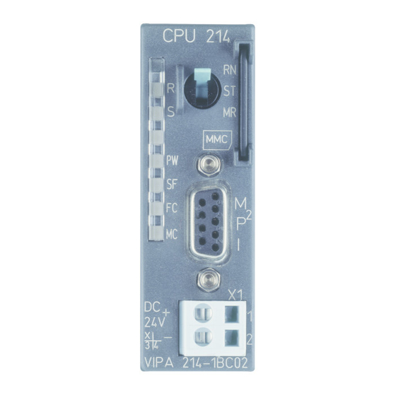
Manual VIPA System 200V Chapter 2 Hardware description Structure Operating mode switch Front view CPU 21x LEDs of the CPU CPU 21x Slot for MMC memory card I interface Slot for DC 24V power supply VIPA 21x-1Bx06 MP I Interfaces... - Page 30 CPUs that are linked over MPI. For a serial exchange between the partners you normally need a special MPI-converter. But now you are also able to use the VIPA "Green Cable" (Order-No. VIPA 950-0KB00), which allows you to establish a serial peer- to-peer connection over the MPI interface.
- Page 31 By Switching to MR (Memory Reset) you request an overall reset with following load from MMC, if a project there exists. You may install a VIPA MMC memory card in this slot as external storage MMC slot device (Order No.: VIPA 953-0KX10).
-
Page 32: Technical Data
Chapter 2 Hardware description Manual VIPA System 200V Technical Data 214-1BC06 Order no. 214-1BC06 Type CPU 214C Technical data power supply Power supply (rated value) DC 24 V Power supply (permitted range) DC 20.4...28.8 V Reverse polarity protection Current consumption (no-load operation) Current consumption (rated value) 1.5 A... - Page 33 Manual VIPA System 200V Chapter 2 Hardware description Order no. 214-1BC06 Time Real-time clock buffered Clock buffered period (min.) 30 d Accuracy (max. deviation per day) 10 s Number of operating hours counter Clock synchronization Synchronization via MPI Synchronization via Ethernet (NTP)
- Page 34 Chapter 2 Hardware description Manual VIPA System 200V Order no. 214-1BC06 Transmission speed, min. 19.2 kbit/s Transmission speed, max. 187.5 kbit/s Datasizes Input bytes Output bytes Parameter bytes Diagnostic bytes Housing Material PPE / PA 6.6 Mounting Profile rail 35 mm...
- Page 35 Manual VIPA System 200V Chapter 2 Hardware description 214-1BA06 Order no. 214-1BA06 Type CPU 214 Technical data power supply Power supply (rated value) DC 24 V Power supply (permitted range) DC 20.4...28.8 V Reverse polarity protection Current consumption (no-load operation) Current consumption (rated value) 1.5 A...
- Page 36 Chapter 2 Hardware description Manual VIPA System 200V Order no. 214-1BA06 Number of operating hours counter Clock synchronization Synchronization via MPI Synchronization via Ethernet (NTP) Address areas (I/O) Input I/O address area 1024 Byte Output I/O address area 1024 Byte...
- Page 37 Manual VIPA System 200V Chapter 2 Hardware description Order no. 214-1BA06 Output bytes Parameter bytes Diagnostic bytes Housing Material PPE / PA 6.6 Mounting Profile rail 35 mm Mechanical data Dimensions (WxHxD) 25.4 x 76 x 80 mm Weight 100 g...
- Page 38 Chapter 2 Hardware description Manual VIPA System 200V 215-1BA06 Order no. 215-1BA06 Type CPU 215 Technical data power supply Power supply (rated value) DC 24 V Power supply (permitted range) DC 20.4...28.8 V Reverse polarity protection Current consumption (no-load operation) Current consumption (rated value) 1.5 A...
- Page 39 Manual VIPA System 200V Chapter 2 Hardware description Order no. 215-1BA06 Number of operating hours counter Clock synchronization Synchronization via MPI Synchronization via Ethernet (NTP) Address areas (I/O) Input I/O address area 1024 Byte Output I/O address area 1024 Byte...
- Page 40 Chapter 2 Hardware description Manual VIPA System 200V Order no. 215-1BA06 Output bytes Parameter bytes Diagnostic bytes Housing Material PPE / PA 6.6 Mounting Profile rail 35 mm Mechanical data Dimensions (WxHxD) 25.4 x 76 x 80 mm Weight 100 g...
-
Page 41: Chapter 3 Deployment Cpu 21X-1Bx06
Project transfer................... 3-14 Operating modes................3-18 Overall reset..................3-20 Firmware update ................3-22 Factory reset ..................3-24 VIPA specific diagnostic entries............3-25 Using test functions for control and monitoring of variables ....3-27 HB97E - CPU - RE_21x-1Bx06 - Rev. 13/20... -
Page 42: Assembly
On a start-up with an empty battery the SF LED is on and thus points to an entry in the diagnostic buffer. Information about the Event-IDs can be found at "VIPA specific diagnostic entries". Attention! After a power reset and with an empty battery the CPU starts with a BAT error and executes an overall reset. -
Page 43: Addressing
Manual VIPA System 200V Chapter 3 Deployment CPU 21x-1Bx06 Addressing Automatic To provide specific addressing of the installed peripheral modules, certain addressing addresses must be allocated in the CPU. The CPU contains a peripheral area (addresses 0 ... 1023) and a process image of the inputs and the outputs (for both each address 0 ... - Page 44 Chapter 3 Deployment CPU 21x-1Bx06 Manual VIPA System 200V Example for auto- The following figure illustrates the automatic allocation of addresses: matic address allocation Slot: Peripheral area Peripheral area rel. Addr rel. Addr. Input byte 0 Output byte 0 Input byte 1...
-
Page 45: Hints For The Deployment Of The Mpi Interface
Important notes for the deployment of MPI cables! Deploying MPI cables at the CPUs from VIPA, you have to make sure that Pin 1 is not connected. This may cause transfer problems and in some cases damage the CPU! Especially PROFIBUS cables from Siemens, like e.g. -
Page 46: Simatic Manager - Limitations
VIPA-CPU. • In contrast to the Siemens CPU 315-2AG10 with a periphery address area 0 to 2047, the periphery address area of the VIPA-CPU is limited to 0 to 1023. • The bit memory (retentive memory) area is limited to 0 to 1023. -
Page 47: Hardware Configuration - Cpu
• Serial connection to the CPU (e.g. MPI-Adapter) Note! The configuration of the CPU requires a thorough knowledge of the Siemens SIMATIC manager and the hardware configurator! • Go to www.vipa.com > Service > Download > PROFIBUS GSD files and Including the GSD-file download the file System_100V_-_200V_Vxxx.zip. - Page 48 Chapter 3 Deployment CPU 21x-1Bx06 Manual VIPA System 200V Proceeding To be compatible with the Siemens SIMATIC manager the following steps should be executed: • Start the hardware configurator from Siemens with a new project. Slot Module PROFIBUS (1): DP master system (1) •...
-
Page 49: Hardware Configuration - I/O Modules
Manual VIPA System 200V Chapter 3 Deployment CPU 21x-1Bx06 Hardware configuration - I/O modules Hardware After the hardware configuration of the CPU place the System 200V configuration of modules in the plugged sequence. the modules In order to address the installed peripheral modules individually, specific addresses in the CPU have to be assigned to them. -
Page 50: Setting Cpu Parameters
Chapter 3 Deployment CPU 21x-1Bx06 Manual VIPA System 200V Setting CPU parameters Parameterization Since the CPU from VIPA is to be configured as Siemens CPU 315-2DP via Siemens (315-2AG10-0AB00 V2.6) in the Siemens hardware configurator, the CPU 315-2AG10 parameters of the VIPA CPU may be set with "Object properties" of the CPU 315-2DP during hardware configuration. - Page 51 The VIPA CPU is preset such that OB 85 is not called if an I/O access error occurs and no entry is made in the diagnostic buffer either.
- Page 52 Chapter 3 Deployment CPU 21x-1Bx06 Manual VIPA System 200V Retentive Memory Number of Memory Enter the number of retentive memory bytes from memory byte 0 onwards. Bytes from MB0 Retentive values > 1024 are not allowed. Number of S7 Enter the number of retentive S7 timers from T0 onwards. Each S7 timer Timers from T0 occupies 2bytes.
- Page 53 Manual VIPA System 200V Chapter 3 Deployment CPU 21x-1Bx06 Execution Enter the time intervals in ms, in which the watchdog interrupt OBs should be processed. The start time for the clock is when the operating mode switch is moved from STOP to RUN.
-
Page 54: Project Transfer
The single participants are connected with each other via bus interface plugs and PROFIBUS cables. Per default the MPI net runs with 187.5kbaud. VIPA CPUs are delivered with MPI address 2. The MPI programming cables are available at VIPA in different variants. - Page 55 The "Green Cable" has the order number VIPA 950-0KB00. Attention! Please regard, that you may use the "Green Cable" exclusively at VIPA CPUs with MP I-interface! Please regard the hints for deploying the Green Cable and the MP...
- Page 56 VIPA System components. The Green Cable is a programming and download cable for VIPA CPUs I jack and VIPA field bus masters. The Green Cable from VIPA is available under the order no. VIPA 950-0KB00. The Green Cable allows you to: •...
- Page 57 To monitor the diagnosis entries, you select PLC > Module Information in the Siemens SIMATIC manager. Via the register "Diagnostic Buffer" you reach the diagnosis window. Information about the Event-IDs can be found at "VIPA specific diagnostic entries". HB97E - CPU - RE_21x-1Bx06 - Rev. 13/20...
-
Page 58: Operating Modes
Chapter 3 Deployment CPU 21x-1Bx06 Manual VIPA System 200V Operating modes Overview The CPU can be in one of 3 operating modes: • Operating mode STOP • Operating mode START-UP • Operating mode RUN Certain conditions in the operating modes START-UP and RUN require a specific reaction from the system program. - Page 59 (parameterizable min. 1ms) that stop res. execute a RESET at the CPU in case of an error and set it into a defined STOP state. The VIPA CPUs are developed function secure and have the following system properties: Event...
-
Page 60: Overall Reset
Chapter 3 Deployment CPU 21x-1Bx06 Manual VIPA System 200V Overall reset Overview During the overall reset the entire user memory is erased. Data located in the memory card is not affected. You have 2 options to initiate an overall reset: •... - Page 61 Manual VIPA System 200V Chapter 3 Deployment CPU 21x-1Bx06 Automatic reload If there is a project S7PROG.WLD on the MMC, the CPU attempts to reload this project from MMC → the MC LED is on. When the reload has been completed the LED is extinguished. The operating mode of the CPU will be STOP or RUN, depending on the position of the function selector.
-
Page 62: Firmware Update
Chapter 3 Deployment CPU 21x-1Bx06 Manual VIPA System 200V Firmware update Overview There is the opportunity to execute a firmware update for the CPU and its components via . For this an accordingly prepared MMC must be in the CPU during the startup. - Page 63 CPU, for example if the voltage supply is interrupted during transfer or if the firmware file is defective. In this case, please call the VIPA-Hotline! Please regard that the version of the update firmware has to be different from the existing firmware otherwise no update is executed.
-
Page 64: Factory Reset
Chapter 3 Deployment CPU 21x-1Bx06 Manual VIPA System 200V Factory reset Proceeding With the following proceeding the internal RAM of the CPU is completely deleted and the CPU is reset to delivery state. Please note that here also the MPI address is reset to the address 2! 1. - Page 65 Entries in the You may read the diagnostic buffer of the CPU via the Siemens SIMATIC diagnostic buffer manager. Besides of the standard entries in the diagnostic buffer, the VIPA CPUs support some additional specific entries in form of event-IDs. Monitoring the To monitor the diagnostic entries you choose the option PLC >...
- Page 66 Zinfo2: Slot 0xE004 Multiple parameterization of a I/O address Zinfo1: I/O address Zinfo2: Slot 0xE005 Internal error – Please contact the VIPA-Hotline! 0xE006 Internal error – Please contact the VIPA-Hotline! 0xE007 Configured in-/output bytes do not fit into I/O area 0xE008 Internal error –...
- Page 67 Manual VIPA System 200V Chapter 3 Deployment CPU 21x-1Bx06 Using test functions for control and monitoring of variables Overview For troubleshooting purposes and to display the status of certain variables you can access certain test functions via the menu item Debug of the Siemens SIMATIC manager.
- Page 68 Chapter 3 Deployment CPU 21x-1Bx06 Manual VIPA System 200V PLC > This test function returns the condition of a selected operand (inputs, Monitor/Modify outputs, flags, data word, counters or timers) at the end of program- Variables execution. This information is obtained from the process image of the selected operands.
- Page 69 Configuration with Siemens TIA Portal Overview In this chapter the project engineering of the VIPA CPU in the Siemens TIA Portal is shown. The chapter only describes the basic usage of the Siemens TIA Portal together with a VIPA CPU.
- Page 70 - OBs • OB 56 "Update interrupt" is not supported by the VIPA-CPU • OB 81 "Error in power supply" exists in the VIPA-CPU but is not supported by the Siemens TIA Portal • The phase shift, available for the OB 35 "Watchdog" in the Siemens TIA Portal, is not evaluated by the VIPA-CPU.
-
Page 71: Chapter 4 Configuration With Siemens Tia Portal
TIA Portal - Work environment TIA is the abbreviation for Totally integrated Automation from Siemens. General Here your VIPA PLCs may be configured and linked. For diagnostics online tools are available. Note! Information about the Siemens TIA Portal may be found in the online help respectively in the according online documentation. - Page 72 Chapter 4 Configuration with Siemens TIA Portal Manual VIPA System 200V Basically, the TIA Portal has the following 2 views. With the button on the Work environment left below you can switch between these views: of the TIA Portal Portal view The Portal view provides a "task oriented"...
-
Page 73: Tia Portal - Hardware Configuration - Cpu
TIA Portal - Hardware Configuration - CPU General The hardware configuration of the CPU and the system 200V modules at the VIPA bus takes place in the Siemens TIA Portal as a virtual PROFIBUS systems. For the PROFIBUS interface is standardized software sided, the functionality is guaranteed by including a GSD-file into the Siemens TIA Portal. - Page 74 Manual VIPA System 200V Proceeding To be compatible with the Siemens TIA Portal the VIPA CPU is to be configured as CPU 315-2DP (6ES7 315-2AG10-0AB0 V2.6) from Siemens. The evolvement of the CPU 21x takes place as a virtual PROFIBUS master system with the following proceeding: •...
- Page 75 Configure a PROFIBUS master "DP-Master". system Note! Thus, the VIPA components can be displayed, you have to deactivate the "Filter" of the hardware catalog. • Switch in the Project area to "Network view". Connect VIPA_CPU21x • Connect the slave system "VIPA_CPU 21x". After installing the vipa_21x.GSD this may be found in the hardware catalog at:...
-
Page 76: Tia Portal - Hardware Configuration - I/O Modules
Chapter 4 Configuration with Siemens TIA Portal Manual VIPA System 200V TIA Portal - Hardware configuration - I/O modules Hardware After the hardware configuration of the CPU place the System 200 modules configuration of at the bus in the plugged sequence. -
Page 77: Tia Portal - Project Transfer
There are the following possibilities for project transfer into the CPU: • Transfer via MPI • Transfer via MMC Currently the VIPA programming cables for transfer via MPI are not Transfer via MPI supported. This is only possible with the programming cable from Siemens. - Page 78 To monitor the diagnosis entries, you select Online & Diagnostics in the Siemens TIA Portal. Via the register "Diagnostic Buffer" you reach the diagnosis window. Information about the Event-IDs can be found at "VIPA specific diagnostic entries". 4-10 HB97E - CPU - RE_21x-1Bx06 - Rev. 13/20...
Need help?
Do you have a question about the CPU Series and is the answer not in the manual?
Questions and answers