Table of Contents
Advertisement
Quick Links
Advertisement
Table of Contents

Related Manuals for VIPA CPU 21 Series


Summary of Contents for VIPA CPU 21 Series
- Page 1 Manual VIPA CPU 21x Order No.: VIPA HB103E Rev. 05/45...
- Page 2 Lerrzeichen...
- Page 3 Manual VIPA CPU 21x About this Manual The information in this manual is supplied without warranties. Information is subject to change without notice. © Copyright 2005 VIPA, Gesellschaft für Visualisierung und Prozess- automatisierung mbH Ohmstraße 4, D-91074 Herzogenaurach, Tel.: +49 (91 32) 744 -0 Fax.: +49 (91 32) 744-144...
-
Page 4: About This Manual
About this manual This manual describes the operation of the CPU 21x in the System 200V from VIPA. The text provides details on the hardware, the programming and the functions integrated into the unit as well as Profibus and Ethernet applications. - Page 5 Content of this chapter is the deployment of the CPU 21x-2BS02 with two RS232C interfaces. Chapter 11: Integrated OBs, SFBs, SFCs Here you find the description of the integrated VIPA-specific SFCs, like e.g. the SFCs for the CP communication. Chapter 12: Command list This chapter lists all available commands of the CPU in alphabetical order.
- Page 6 About this Manual Manual VIPA CPU 21x Subject to change to cater for technical progress.
-
Page 7: Table Of Contents
Principles................. 1-1 Safety information for users ..............1-2 Hints for the deployment of the MPI interface........1-3 Hints for the Green Cable from VIPA ........... 1-4 Overview System 200V ................ 1-5 Function security of the VIPA CPUs ............. 1-6 General description of the System 200V ..........1-7 Overview CPU 21x ................ - Page 8 Contents Manual VIPA CPU 21x Chapter 5 Deployment CPU 21x-2BT02 with H1 / TCP/IP ....5-1 Principles....................5-2 Network planning ................. 5-7 Ethernet and IP addresses..............5-9 Project Engineering of the CPU 21x-2BT02 ........5-11 Configuration example CPU 21x-2BT02..........5-24 Start-up behavior................
- Page 9 Transfer instructions................. 12-22 Data type conversion instructions............. 12-25 Comparison instructions..............12-26 Combination instructions (Bit)............12-27 Combination instructions (Word) ............12-33 Timer instructions................12-33 Counter instructions ................. 12-34 VIPA specific diagnostic entries ............12-35 Appendix ....................A-1 Index ....................A-1 HB103E - Rev. 05/45...
- Page 10 Contents Manual VIPA CPU 21x HB103E - Rev. 05/45...
-
Page 11: User Considerations
It contains a description of the construction, project implemen- contents tation and the application of the product. The CPU 21x is compatible with all System 200V components of VIPA. The manual is targeted at users who have a background in automation Target audience technology and PLC-programming. -
Page 12: Safety Information
Safety information The CPU 21x is constructed and manufactured for Application specifications • all VIPA System 200V components • communication and process control • general control and automation tasks • industrial applications • operation within the environmental conditions specified in the technical data •... -
Page 13: Chapter 1 Principles
Principles................. 1-1 Safety information for users ..............1-2 Hints for the deployment of the MPI interface........1-3 Hints for the Green Cable from VIPA ........... 1-4 Overview System 200V ................ 1-5 Function security of the VIPA CPUs ............. 1-6 General description of the System 200V ..........1-7 Overview CPU 21x ................ -
Page 14: Safety Information For Users
Chapter 1 Principles Manual VIPA CPU 21x Safety information for users VIPA modules make use of highly integrated components in MOS- Handling of technology. These components are extremely sensitive to over-voltages electrostatically that may occur during electrostatic discharges. sensitive modules... -
Page 15: Hints For The Deployment Of The Mpi Interface
Important notes for the deployment of MPI cables! Deploying MPI cables at the CPUs from VIPA, you have to make sure that Pin 1 is not connected. This may cause transfer problems and in some cases damage the CPU! Especially Profibus cables from Siemens, like e.g. -
Page 16: Hints For The Green Cable From Vipa
Note to the application area The Green Cable may exclusively deployed directly at the concerning jacks of the VIPA components (in between plugs are not permitted). E.g. a MPI cable has to be disconnected if you want to connect a Green Cable. -
Page 17: Overview System 200V
Manual VIPA CPU 21x Chapter 1 Principles Overview System 200V The System 200V is a modular automation system for low and middle The System 200V range of performance that you may use either centralized or decentralized. The single modules are directly clipped to a 35mm DIN rail and are connected together with the help of special bus clips. -
Page 18: Function Security Of The Vipa Cpus
(parameterizable min. 1ms) that stop res. execute a RESET at the CPU in case of an error and set it into a defined STOP state. The VIPA CPUs are developed function secure and have the following system properties: Event... -
Page 19: General Description Of The System 200V
Manual VIPA CPU 21x Chapter 1 Principles General description of the System 200V • Norm profile head rail 35mm Structure / Dimensions • Peripheral modules with labeling strip • Measurements basic module: Single width: (HxWxD) in mm: 76x25.4x80; in inches: 3x1x3 Double width: (HxWxD) in mm: 76x50.8x80;... -
Page 20: Overview Cpu 21X
CPUs are visually on the same lines. With rising number the scope of performance of a CPU 21x is increasing. Note! The remainder of this description refers to all CPUs of the VIPA CPU 21x family! HB103E - Rev. 05/45... -
Page 21: Hints For Project Engineering
• The GSD-file for the System 200V is included to the hardware configurator. Actual GSD files can be found at ftp://ftp.vipa.de/support. • serial connection to the CPU (e.g. via "Green Cable" from VIPA) Note! The configuration of the CPU requires a thorough knowledge of the... - Page 22 Chapter 1 Principles Manual VIPA CPU 21x Project The following steps are necessary to project a CPU 21x in the hardware configurator from Siemens: engineering • Start the hardware configurator from Siemens. CPU 21x with central periphery • Install the GSD-file VIPA_21x.gsd.
- Page 23 Manual VIPA CPU 21x Chapter 1 Principles Project When configuring a CPU 21xDP, the central plugged-in modules are parameterized like shown above. engineering of the CPU 21xDP in a Slave parameterization master system As intelligent slave, the Profibus section maps its data areas into the memory area of the CPU 21xDP.
- Page 24 Chapter 1 Principles Manual VIPA CPU 21x Project The project engineering of network connections via Ethernet for the CPU 21x-2BT02 can be carried out with WinNCS from VIPA and for the engineering CPU21x-2BT10 with SIMATIC Manager using NetPro. CPU 21xNET...
-
Page 25: Application Fields
This series of CPU modules provides access to the peripheral modules of Overview the VIPA System 200V. You can use a set of standard commands and programs to interrogate sensors and actuators. One single CPU may address a maximum of central 32 modules. -
Page 26: Features
Chapter 1 Principles Manual VIPA CPU 21x Application based on TCP/IP VIPA Rack-135U Visualization and shop floor data collection via DDE-server CP 143 TCP/IP TCP/IP VIPA Rack-135U System 200V System 200V CP 143 TCP/IP CPU 21x NET CPU 21x NET Features The PLC-CPUs are employed as program executor. -
Page 27: Operating Modes Of A Cpu
Manual VIPA CPU 21x Chapter 1 Principles Operating modes of a CPU These CPUs are intended for small and medium sized applications and are General supplied with an integrated 24V power supply. The CPU contains a standard processor with internal program memory. In combination with the System 200V peripherals the unit provides a powerful solution for process automation applications within the System 200V family. -
Page 28: Cpu 21X Programs
Chapter 1 Principles Manual VIPA CPU 21x CPU 21x programs The program that is present in every CPU is divided as follows: Overview • System routine • User program System routine The system routine organizes all those functions and procedures of the CPU that are not related to a specific control application. - Page 29 Manual VIPA CPU 21x Chapter 1 Principles Bit memory Bit memory is an area of memory that is accessible to the user program by means of certain operations. Bit memory is intended to store frequently used working data. You may access the following types of data:...
- Page 30 Chapter 1 Principles Manual VIPA CPU 21x 1-18 HB103E - Rev. 05/45...
-
Page 31: Chapter 2 Hardware Description
Manual VIPA CPU 21x Chapter 2 Hardware description Chapter 2 Hardware description The CPUs 21x are available in different versions that are described in this Outline chapter. In addition to the hardware description the chapter also contains installation and commissioning instructions and applications for the memory modules. -
Page 32: System Overview
Chapter 2 Hardware description Manual VIPA CPU 21x System overview The CPU-21x family of products available from VIPA consists of 3 different CPU versions models each with 8 versions: • CPU 21x PLC-CPU • CPU 21x-2BT10 PLC-CPU with Ethernet interface with TCP-IP •... - Page 33 Manual VIPA CPU 21x Chapter 2 Hardware description • Instruction set compatible with Siemens STEP CPU 21x • MPI interface for data transfer between PC and CPU • Status LEDs for operating mode and diagnostics • External memory card (MMC) •...
- Page 34 Type Order number Description CPU 21xNET CPU 214NET VIPA 214-2BT10 PLC CPU 214 with Ethernet and 48/80KB of work/load memory CPU 215NET VIPA 215-2BT10 PLC CPU 215 with Ethernet and 96/144KB of work/load memory CPU 216NET VIPA 216-2BT10 PLC CPU 216 with Ethernet and 128/192KB of work/load memory HB103E - Rev.
- Page 35 Type Order number Description CPU 21xNET CPU 214NET VIPA 214-2BT02 PLC CPU 214 with Ethernet and 48/80KB of work/load memory CPU 215NET VIPA 215-2BT02 PLC CPU 215 with Ethernet and 96/144KB of work/load memory CPU 216NET VIPA 216-2BT02 PLC CPU 216 with Ethernet and 128/192KB of work/load memory HB103E - Rev.
- Page 36 Type Order number Description CPU 21xDPM CPU 214DPM VIPA 214-2BM02 PLC CPU 214 with Profibus-DP master and 48/80KB of work/load memory CPU 215DPM VIPA 215-2BM02 PLC CPU 215 with Profibus-DP master and 96/144KB of work/load memory CPU 216DPM VIPA 216-2BM02 PLC CPU 216 with Profibus-DP master and 128/192KB of work/load memory HB103E - Rev.
- Page 37 Order data Type Order number Description CPU 21xDP CPU 214DP VIPA 214-2BP02 SPS CPU 214 with Profibus slave and 48/80KB of work/load memory CPU 215DP VIPA 215-2BP02 SPS CPU 215 with Profibus slave and 96/144KB of work/load memory CPU 216DP...
- Page 38 Type Order number Description CPU 21xCAN CPU 214CAN VIPA 214-2CM02 PLC CPU 214 with CAN master and 48/80KB of work/load memory CPU 215CAN VIPA 215-2CM02 PLC CPU 215 with CAN master and 96/144KB of work/load memory CPU 216CAN VIPA 216-2CM02 PLC CPU 216 with CAN master and 128/192KB of work/load memory HB103E - Rev.
- Page 39 Manual VIPA CPU 21x Chapter 2 Hardware description CPU 21xSER-1 Identical to CPU 21x, additionally with: • Serial Communication via two COM interfaces (RS232C or RS485) • LEDs for communication CPU 214SER CPU 215SER CPU 216SER VIPA 214-2BS12 VIPA 215-2BS12...
- Page 40 Order data Type Order number Description CPU 21xSER-2 CPU 214SER VIPA 214-2BS02 SPS CPU 214 with 2xRS232C interface and 48/80kByte of work/load memory CPU 215SER VIPA 215-2BS02 SPS CPU 215 with 2xRS232C interface and 96/144kByte of work/load memory CPU 216SER...
-
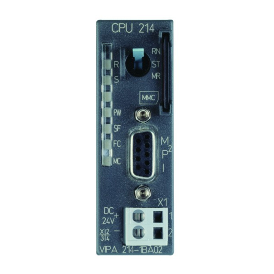
Page 41: Structure
Manual VIPA CPU 21x Chapter 2 Hardware description Structure RUN/STOP/OVERALL RESET CPU 216 Front view function selector CPU 21x Status indicator LEDs CPU Slot for MMC memory card I interface Connector for 24V DC power supply VIPA 216-2BA02 RUN/STOP/OVERALL RESET... - Page 42 Chapter 2 Hardware description Manual VIPA CPU 21x RUN/STOP/OVERALL RESET CPU 216DP Front view function selector CPU 21xDP Status indicator LEDs CPU Slot for MMC memory card I interface Connector for 24V DC power supply Status indicator LEDs Profibus-DP slave...
-
Page 43: Components
You may issue an overall reset by placing the switch in the Memory Reset (MR) position. MMC slot memory You may install a VIPA MMC memory card in this slot as external storage device (Order No.: VIPA 953-0KX00). card The access to the MMC takes always place after an overall reset. - Page 44 CPUs that are linked over MPI. For a serial exchange between the partners you normally need a special MPI-converter. But now you are also able to use the VIPA "Green Cable" (Order-No. VIPA 950-0KB00), which allows you to establish a serial peer- to-peer connection over the MPI interface.
- Page 45 Manual VIPA CPU 21x Chapter 2 Hardware description In addition to the components described in the section on the CPU 21x the CPU 21x-2BT10 CPU 21x-2BT10 module is provided with further LEDs and an Ethernet interface located at the left-hand side of the module.
- Page 46 Chapter 2 Hardware description Manual VIPA CPU 21x In addition to the components described in the section on the CPU 21x the CPU 21x-2BT02 CPU 21x-2BT02 module is provided with further LEDs and an Ethernet interface located at the left-hand side of the module.
- Page 47 Manual VIPA CPU 21x Chapter 2 Hardware description In addition to the components described in the section on the CPU 21x the CPU 21xDPM CPU 21xDPM module is provided with 4 more LEDs and a Profibus interface. LEDs The LEDs are located in the left half of the front panel and they are used for diagnostic purposes.
- Page 48 Chapter 2 Hardware description Manual VIPA CPU 21x In addition to the components described in the section on the CPU 21x the CPU 21xDP CPU 21xDP module is provided with 3 more LEDs and a Profibus interface. The LEDs are located in the left half of the front panel and they are used LEDs for diagnostic purposes.
- Page 49 Manual VIPA CPU 21x Chapter 2 Hardware description In addition to the components described in the section on the CPU 21x the CPU 21xCAN CPU 21xCAN module is provided with 4 more LEDs and a CAN interface. The LEDs are located in the left half of the front panel and they are used LEDs for diagnostic purposes.
- Page 50 Chapter 2 Hardware description Manual VIPA CPU 21x Additional to the components described before, the CPU 21x with order no. CPU 11xSER-1 21x-2BS12 has an RS232C interface and the CPU 21x with order no. 21x-2BS32 an RS485 interface. LEDs The LEDs are located in the left half of the front panel and they are used for diagnostic purposes.
- Page 51 Manual VIPA CPU 21x Chapter 2 Hardware description In addition to the components described in the section on the CPU 21x the CPU 21xSER-2 CPU 21xSER-2 module is provided with more LEDs and two serial RS232C interfaces. LEDs The LEDs are located in the left half of the front panel and they are used for diagnostic purposes.
-
Page 52: Block Diagram
Chapter 2 Hardware description Manual VIPA CPU 21x Block diagram The following block diagram shows the basic hardware construction of the CPU 21x modules: Voltage monitor RUN/STOP/MR Pulse RESET DC 24V Power supply Memory-Card Processor Clock PU/AG System 200V interface circuitry... -
Page 53: Technical Data
Manual VIPA CPU 21x Chapter 2 Hardware description Technical data CPU 21x General Electrical data VIPA 214-1BC02, VIPA 214-1BA02 ... VIPA 216-1BA02 Power supply DC 24V (20.4 ... 28.8V) Current consumption max. 1.5A Dissipation power max. 3.5W Status indicators (LEDs) - Page 54 Chapter 2 Hardware description Manual VIPA CPU 21x CPU 21x-2BT10 Electrical data VIPA 214-2BT10 ... VIPA 216-2BT10 Power supply DC 24V (20.4 ... 28.8V) Current consumption max. 1.5A Dissipation power max. 6W ≥ 500V AC to Ethernet Potential separation Status indicator (LEDs)
- Page 55 Manual VIPA CPU 21x Chapter 2 Hardware description CPU 21xDPM Electrical Data VIPA 214-2BM02 ... VIPA 216-2BM02 Power supply DC 24V (20.4 ... 28.8V) Current consumption max. 1.5A Dissipation power max. 5W ≥ 500V AC to fieldbus Potential separation Status monitoring (LEDs)
- Page 56 Chapter 2 Hardware description Manual VIPA CPU 21x CPU 21xCAN Electrical Data VIPA 214-2CM02 ... VIPA 216-2CM02 Power supply DC 24V (20.4 ... 28.8V) Current consumption max. 1.5A Dissipation power max. 5W ≥ 500V AC to fieldbus Potential separation Status monitoring (LEDs)
- Page 57 RS485 interface integrated Dimensions and weight Dimensions (WxHxD) in mm 50.8x76x80 Weight 150g CPU 21xSER-2 Electrical data VIPA 214-2BS02 ... VIPA 216-2BS02 Power supply DC 24V (20.4 ... 28.8V) Current consumption max. 1.5A Dissipation power max. 5W Potential separation Status indicator (LEDs)
- Page 58 Chapter 2 Hardware description Manual VIPA CPU 21x 2-28 HB103E - Rev. 05/45...
-
Page 59: Chapter 3 Deployment Cpu 21X
Manual VIPA CPU 21x Chapter 3 Deployment CPU 21x Chapter 3 Deployment CPU 21x This chapter describes the deployment of the CPU 21x together with the Outline peripheral modules of the System 200V. Besides commissioning and start-up behavior you will find here also a description of the project engineering, parameterization, operating modes and test functions. -
Page 60: Assembly
CPU, double width CPU, single width Peripheral modules Guiding bars CPU 216 VIPA 216-2BA01 CPU 216DP VIPA 216-2BP02 Clack For details on the assembly of System 200V modules please refer to the System 200V manual (Order-No.: VIPA HB97). HB103E - Rev. 05/45... -
Page 61: Start-Up Behavior
Manual VIPA CPU 21x Chapter 3 Deployment CPU 21x Start-up behavior After turning on the power supply, the CPU switches to the operating mode Turn on that is fixed by the operating mode lever at the CPU. power supply Now you may transfer your project from your projecting tool into the CPU via MPI resp. -
Page 62: Address Allocation
Chapter 3 Deployment CPU 21x Manual VIPA CPU 21x Address allocation Automatic To provide specific addressing of the installed peripheral modules, certain addresses must be allocated in the CPU. addressing The CPU contains a peripheral area (addresses 0 ... 1023) and a process image of the inputs and the outputs (for both each address 0 ... - Page 63 Manual VIPA CPU 21x Chapter 3 Deployment CPU 21x Example for auto- The following figure illustrates the automatic allocation of addresses: matic address allocation Plug-in location: Peripheral area Peripheral area rel. Addr rel. Addr. Input byte 0 Output byte 0...
-
Page 64: Project Engineering
For the employment of the CPU 21x from VIPA using the Siemens Fast introduction SIMATIC Manager the inclusion of the System 200V via the vipa GSD file in the hardware catalog is required. To be compatible with the Siemens SIMATIC Manager you have to execute the following steps: •... - Page 65 Manual VIPA CPU 21x Chapter 3 Deployment CPU 21x • Go to www.vipa.de > Service > Download > GSD- und EDS- Files > Including the GSD- file Profibus and download the file Cx000023_Vxxx. • Extract the file to your work directory. The vipa_21x.gsd (german) respectively vipa_21x.gse (english) can be found at the directory...
- Page 66 Transferring the Data is transferred between the CPU and the PC via MPI. If your PG has no MPI functionality you may use the VIPA "Green Cable" to send the data project serial by a peer-to-peer connection. The VIPA "Green Cable" has the OrderNo.
-
Page 67: Configuration Of The Cpu Parameters
Manual VIPA CPU 21x Chapter 3 Deployment CPU 21x Configuration of the CPU parameters Outline Except of the Profibus parameters of the CPU 21xDP the CPU parameterization takes place in the parameter dialog of the CPU 315- 2DP. The parameterization of the Profibus section of the CPU 21xDP takes place via the parameterization dialog of the CPU 21xDP. - Page 68 Chapter 3 Deployment CPU 21x Manual VIPA CPU 21x Supported The CPU 21x doesn't use all the parameters that may be defined in the Siemens SIMATIC Manager. parameters The following parameters are currently employed by the CPU: General: Time-of-Day Interrupts:...
-
Page 69: Project Transfer
• Connect your PG resp. PC with your CPU via MPI. Approach If your PG doesn't support MPI, you may use the VIPA "Green Cable" to establish a point-to-point connection. The "Green Cable" has the order number VIPA 950-0KB00 and may only be used with MPI interface of VIPA CPUs. - Page 70 Hints for configuring a MPI interface are to find in the documentation of Configure MPI your programming software. At this place only the usage of the "Green Cable" from VIPA shall be shown, together with the programming tool from Siemens. The "Green Cable" establishes a connection between the COM interface of the PC and the MP I interface of the CPU.
- Page 71 The reading of the MMC takes always place after an OVERALL RESET. You may write on the MMC via a write command from the hardware configurator from Siemens or with a MMC reading device from VIPA (OrderNo.: VIPA 950-0AD00). Thus it is possible to create your applications at the PC, copy them on MMC and transfer them into the CPU by plugging-in the MMC.
-
Page 72: Operating Modes
Chapter 3 Deployment CPU 21x Manual VIPA CPU 21x Operating modes The CPU can be in one of 3 operating modes: Outline • STOP • START-UP • RUN Certain conditions in the operating modes START-UP and RUN require a specific reaction from the system program. In this case the application interface is often provided by a call to an organization block that was included specifically for this event. -
Page 73: Overall Reset
Manual VIPA CPU 21x Chapter 3 Deployment CPU 21x Overall Reset During the OVERALL_RESET the entire user memory (RAM) is erased. Outline Data located in the memory card is not affected. You have 2 options to initiate an OVERALL RESET: •... - Page 74 Chapter 3 Deployment CPU 21x Manual VIPA CPU 21x Automatic reload At this point the CPU attempts to reload the parameters and the program from the memory card. → The lower LED (MC) blinks. When the reload has been completed the LED is extinguished. The operating mode of the CPU will be STOP or RUN, depending on the position of the function selector.
-
Page 75: Firmware Update
Outline starting with firmware version 3.3.3. The latest 2 firmware versions can be found in the service area at www.vipa.de and at the ftp server at ftp.vipa.de. Attention! When installing a new firmware you have to be extremely careful. Under certain circumstances you may destroy the CPU, for example if the voltage supply is interrupted during transfer or if the firmware file is defective. - Page 76 Chapter 3 Deployment CPU 21x Manual VIPA CPU 21x MMC update using By means of reserved file names in the CPU 21x you may transfer the reserved file names firmware updates per MMC for the following components: Component Possible with...
- Page 77 Manual VIPA CPU 21x Chapter 3 Deployment CPU 21x Flowchart for The following flowchart illustrates the CPU behavior at firmware update: firmware update Power Off Plug-in MMC Power On Switch=Stop? CPU goes in RUN SF and FRCE are blinking alternately...
-
Page 78: Using Test Functions For The Control And Monitoring Of Variables
Chapter 3 Deployment CPU 21x Manual VIPA CPU 21x Using test functions for the control and monitoring of variables For troubleshooting purposes and to display the status of certain variables Outline you may access certain test functions via the menu item Test of the Siemens SIMATIC Manager. - Page 79 Manual VIPA CPU 21x Chapter 3 Deployment CPU 21x PLC > This test function returns the condition of a selected operand (inputs, outputs, flags, data word, counters or timer) at the end of program Monitor/control execution. variables This information is obtained from the process image of the selected operands.
- Page 80 Chapter 3 Deployment CPU 21x Manual VIPA CPU 21x 3-22 HB103E - Rev. 05/45...
-
Page 81: Chapter 4 Deployment Of The Cpu 21X-2Bt10 With Tcp/Ip
Manual VIPA CPU 21x Chapter 4 Deployment of the CPU 21x-2BT10 with TCP/IP Chapter 4 Deployment of the CPU 21x-2BT10 with TCP/IP The following chapter describes applications of the CPU 21x-2BT10 and Outline the communication using TCP/IP. Please regard the chapter „Fast introduction“... -
Page 82: Industrial Ethernet In Automation
Chapter 4 Deployment of the CPU 21x-2BT10 with TCP/IP Manual VIPA CPU 21x Industrial Ethernet in automation The flow of information in a company presents a vast spectrum of Overview requirements that must be met by the communication systems. Depending... -
Page 83: Iso/Osi Reference Model
Manual VIPA CPU 21x Chapter 4 Deployment of the CPU 21x-2BT10 with TCP/IP ISO/OSI reference model Overview The ISO/OSI reference model is based on a proposal that was developed by the International Standards Organization (ISO). This represents the first step towards an international standard for the different protocols. It is referred to as the ISO-OSI layer model. - Page 84 Chapter 4 Deployment of the CPU 21x-2BT10 with TCP/IP Manual VIPA CPU 21x Layers Layer 1 Bit communication layer (physical layer) The bit communication layer (physical layer) is concerned with the transfer of data bits via the communication channel. This layer is therefore...
- Page 85 Manual VIPA CPU 21x Chapter 4 Deployment of the CPU 21x-2BT10 with TCP/IP Layers Layer 5 Session layer continued... The session layer is also called the communication control layer. It relieves the communication between service deliverer and the requestor by establishing and holding the connection if the transport system has a short time fail out.
-
Page 86: Principles
Chapter 4 Deployment of the CPU 21x-2BT10 with TCP/IP Manual VIPA CPU 21x Principles Network (LAN) A network res. LAN (local area network) provides a link between different stations that enables them to communicate with each other. Network stations consist of PCs, IPCs, TCP/IP adapters, etc. -
Page 87: Protocols
ISO/OSI layer model, a model based upon seven layers with rules for the usage of hardware and software (see ISO/OSI reference model above). The CPU 21xNET from VIPA uses the following protocols • TCP/IP • UDP •... - Page 88 2000...65535. Partner and local ports may only be identical at one connection. • Not depending on the used protocol, the PLC needs the VIPA handling blocks AG_SEND (FC5) and AG_RECV (FC6) for data transfer.
- Page 89 ASCII or Hex format. Foreign and local TSAPs may only be identical at 1 connection. • Independently of the used protocol the VIPA handling blocks AG_SEND (FC5) and AG_RECEIVE (FC6) are necessary for data transfer. • Contrary to TCP different telegram lengths can be received using RFC1006.
-
Page 90: Ip Address And Subnet
Chapter 4 Deployment of the CPU 21x-2BT10 with TCP/IP Manual VIPA CPU 21x IP address and subnet The IP address is a 32Bit address that must be unique within the network. IP address The IP address consists of 4 numbers that are separated by a full stop. - Page 91 Manual VIPA CPU 21x Chapter 4 Deployment of the CPU 21x-2BT10 with TCP/IP Address classes For IPv4 addresses there are five address formats (class A to class E) that are all of a length of 4 Byte = 32 Bit.
-
Page 92: Network Planning
These agreements define the form of the data protocol, the method of bus access and other principles that are important for reliable communications. The VIPA CPU 21xNET was developed in accordance with the standards defined by ISO. International and national committees have defined the following standards... - Page 93 Manual VIPA CPU 21x Chapter 4 Deployment of the CPU 21x-2BT10 with TCP/IP Overview of The CP is exclusively used for employment in a Twisted-Pair network. Within a Twisted-Pair network all participating stations are connected in components star topology via a Twisted-Pair cable to a hub/switch which is also able to communicate with another hub/switch.
- Page 94 Chapter 4 Deployment of the CPU 21x-2BT10 with TCP/IP Manual VIPA CPU 21x Linking with Please regard that the following software packages must be installed for the project engineering: NetPro • Siemens SIMATIC Manager V. 5.1 and vipa_21x.gsd (is included).
-
Page 95: Communication Possibilities Of The Cp
Communication possibilities of the CP The internal CP of the CPU 21x-2BT10 is directly connected to the CPU via Communication a Dual-Port-RAM. The CPU manages the data exchange with the VIPA between CP 243 handling blocks AG_SEND (FC5) and AG_RECV (FC6). - Page 96 Chapter 4 Deployment of the CPU 21x-2BT10 with TCP/IP Manual VIPA CPU 21x Configurable Configurable connections are connections for the communication between PLC stations. The connections may be configured with the Siemens project connections engineering tool NetPro. The following table shows the combination option with the different...
- Page 97 Here the data transfer happens by call from your user application. The FC5 and FC6 that are part of the VIPA block library are serving as interface. This enables your control to send messages depending on process events.
-
Page 98: Function Overview
Chapter 4 Deployment of the CPU 21x-2BT10 with TCP/IP Manual VIPA CPU 21x Function overview In the following the functions are listed that are supported by the CP of the Outline CPU 21x-2BT10 starting with CP firmware version 1.7.4: Configurable... -
Page 99: Fast Introduction
• PLC programming via user application (connection to PLC) • Transfer of the complete project to CPU Note! To be compatible to the Siemens SIMATIC Manager, the CPU 21x from VIPA has to be configured as CPU 315-2DP (6ES7 315-2AF03-0AB0) V1.2... - Page 100 Chapter 4 Deployment of the CPU 21x-2BT10 with TCP/IP Manual VIPA CPU 21x Assign IP For the assignment of the IP parameters such as IP address, Subnet mask etc. you have the following possibilities: parameters • Online using Siemens SIMATIC Manager via "Assign Ethernet Address"...
- Page 101 PROFIBUS DP \ Additional Field Devices \ IO \ VIPA_System_200V. Assign Profibus address 1 to this slave. • Place the VIPA CPU 21xNET that you want to deploy at the 1 slot. • Include your System 200V modules in the location sequence starting from slot 1.
- Page 102 AG_SEND (FC5) and AG_RECV (FC6) are used. The blocks are part of the VIPA library that is included in the consignment as CD (SW830). Specify the according CP via the parameters ID and LADDR by calling FC5 res. FC6.
-
Page 103: Hardware Configuration
The modules of the System 200V from VIPA are now integrated in the hardware catalog and may be configured. Note To be compatible to Siemens SIMATIC Manager, the CPU 21x from VIPA have to be projected as CPU 315-2DP (6ES7 315-2AF03) V1.2 The CP part from the CPU 21xNET is virtually projected as CP343-1 (343-1EX11) from Siemens at slot 4. - Page 104 "Hardware". • Configure a rack (Simatic300 \ Rack-300 \ Rail). • For all CPUs 21x from VIPA are configured as CPU 315-2DP, you select the CPU 315-2DP in the hardware catalog. This is to find at: SIMATIC 300 \ CPU-300 \ CPU 315-2 DP \ 6ES7 315-2AF03-0AB0 V1.2...
- Page 105 PROFIBUS DP \ Additional Field Devices \ IO \ VIPA_System_200V. Assign Profibus address 1 to this slave. • Place the VIPA CPU 21xNET that you want to deploy at 1 slot. • Include your System 200V modules in the location sequence starting from plug-in location 1.
-
Page 106: Configure Connections
Chapter 4 Deployment of the CPU 21x-2BT10 with TCP/IP Manual VIPA CPU 21x Configure connections The project engineering of connections i.e. the "link-up" between stations Outline happens in NetPro from Siemens. NetPro is a graphical user interface for the link-up of stations. - Page 107 Manual VIPA CPU 21x Chapter 4 Deployment of the CPU 21x-2BT10 with TCP/IP Note! All stations outside of the recent project must be configured as replacement objects like e.g. Siemens "SIMATIC S5" or "other station" or with the object "In unknown project".
- Page 108 Chapter 4 Deployment of the CPU 21x-2BT10 with TCP/IP Manual VIPA CPU 21x PLC stations You receive the following graphical display for every PLC station and their component. By selecting the single components, the context menu offers you several functions:...
- Page 109 Both are parameters that must be given to your PLC application when using the FC 5 and 6 (AG_SEND, AG_RECEIVE). Please do always use the VIPA FCs that are delivered with the SW830 as a library. Note! Please regard that a CP depending ID is assigned to the connections of the SEND/RECEIVE interface.
- Page 110 Chapter 4 Deployment of the CPU 21x-2BT10 with TCP/IP Manual VIPA CPU 21x Addresses The register addresses shows the relevant local and partner address information as suggestion values. Depending on the communication type you may leave the address information unspecified.
- Page 111 Manual VIPA CPU 21x Chapter 4 Deployment of the CPU 21x-2BT10 with TCP/IP Save and compile After you configured all connections this way, you may save and compile your project and exit NetPro. connections To store the CP project engineering data in the system data, you have to activate the option "Store project data in the CPU"...
-
Page 112: Send/Receive With Plc Program
AG_SEND (FC5) and AG_RECV (FC6) are used. By including these blocks into the cycle block OB1 you may send and receive data cyclic. The two FCs are part of the VIPA library, that is included in the consignment as CD (SW830). - Page 113 Manual VIPA CPU 21x Chapter 4 Deployment of the CPU 21x-2BT10 with TCP/IP FC call is faster If a block is called a second time in the user application before the data of than CP transfer the last time is already completely send res. received, the FC block...
- Page 114 Chapter 4 Deployment of the CPU 21x-2BT10 with TCP/IP Manual VIPA CPU 21x AG_SEND (FC5) By means of AG_SEND the data to send are transferred to the CP. Parameter Parameter Declaration Type Description Input BOOL Activation of the sender 0: Updates DONE, ERROR and STATUS...
- Page 115 Manual VIPA CPU 21x Chapter 4 Deployment of the CPU 21x-2BT10 with TCP/IP DONE, ERROR, The following table shows all messages that can be returned by the CP after a SEND res. RECV command. STATUS A "-" means that this message is not available for the concerning SEND res.
- Page 116 Chapter 4 Deployment of the CPU 21x-2BT10 with TCP/IP Manual VIPA CPU 21x ... continue DONE, ERROR, STATUS DONE ERROR STATUS Description (SEND) (RECV) 8F42h Acknowledgement delay at reading a parameter from peripheral area. 8F43h Acknowledgement delay at writing a parameter from peripheral area.
-
Page 117: Project Transfer
"Project transfer". Transfer with MPI programming cable (MPI communication) Transfer via MPI The MPI programming cables from VIPA provide a bus enabled RS485 plug for the MP I jack of the CPU and a RS232 res. USB plug for the PC. - Page 118 Chapter 4 Deployment of the CPU 21x-2BT10 with TCP/IP Manual VIPA CPU 21x The MMC (Memory Card) serves as external storage medium and has the Transfer via FAT16 file system. Your project engineering must be stored in the root directory and requires the file name: S7PROG.WLD.
-
Page 119: Ncm Diagnostic - Help For Error Diagnostic
Manual VIPA CPU 21x Chapter 4 Deployment of the CPU 21x-2BT10 with TCP/IP NCM diagnostic – Help for error diagnostic This page shall help you with the error diagnostic. The following page lists Check list for a number of typical problems and their probable causes:... - Page 120 Chapter 4 Deployment of the CPU 21x-2BT10 with TCP/IP Manual VIPA CPU 21x Start NCM There are two options to start the diagnostic tool: • Via Windows-START menu > SIMATIC ... NCM S7 > Diagnostic diagnostic • Within the project engineering res. the hardware configuration via the register "Diagnostic"...
- Page 121 Manual VIPA CPU 21x Chapter 4 Deployment of the CPU 21x-2BT10 with TCP/IP Read diagnostic The CP has a diagnostic buffer. This has the architecture of a ring memory and may store up to 100 diagnostic messages. The NCM diagnostic allows...
-
Page 122: Coupling To Other Systems
Chapter 4 Deployment of the CPU 21x-2BT10 with TCP/IP Manual VIPA CPU 21x Coupling to other systems The operating mode FETCH/WRITE supported at TCP res. ISO-on-TCP Outline can be used for accesses of partner devices to the PLC system memory. - Page 123 Manual VIPA CPU 21x Chapter 4 Deployment of the CPU 21x-2BT10 with TCP/IP Note! Information about the valid range can be found at Chapter "Hardware description of the CPU". ORG identifier 05h-0Ah CPU area ORG identifier Description source/destination data source/destination data...
- Page 124 Chapter 4 Deployment of the CPU 21x-2BT10 with TCP/IP Manual VIPA CPU 21x Structure of PLC- For every READ and WRITE the CP generates PLC header for request and acknowledgment messages. Normally the length of these headers is Header 16Bytes and have the following structure:...
-
Page 125: Example Communication Cpu21X-2Bt10
Preconditions Knowledge of the VIPA CP handling blocks AG_SEND and AG_RECV is required. CP handling blocks provide the options required to utilize the communication functions in the programs of the PLCs. - Page 126 Chapter 4 Deployment of the CPU 21x-2BT10 with TCP/IP Manual VIPA CPU 21x Station 1 Station 2 Structure System 200V System 200V NetPro CPU 21xNET CPU 21xNET Ethernet The example for the application is based upon a communication task that is...
- Page 127 Manual VIPA CPU 21x Chapter 4 Deployment of the CPU 21x-2BT10 with TCP/IP Steps of project The project engineering is divided into the following steps: • Hardware configuration engineering • CP Project engineering with NetPro • PLC user application • Transfer project •...
- Page 128 Chapter 4 Deployment of the CPU 21x-2BT10 with TCP/IP Manual VIPA CPU 21x Project engineering Start NetPro by selecting the CPU below Station 1 and clicking on the with NetPro object "connections". In NetPro "Station 1" and "Station 2" are listed together with Ethernet.
- Page 129 OB1 with the parameters ID and LADDR you may cyclically send and receive data. The two FCs are part of the VIPA library that is included in the consignment of the CPU as CD. OB 1 Via the cycle OB OB1 the sending and receiving of the data is controlled.
- Page 130 Chapter 4 Deployment of the CPU 21x-2BT10 with TCP/IP Manual VIPA CPU 21x It is assumed, that the CPs are programmed and that an overall reset was Monitoring the issued to the CPUs, where the RUN/STOP switch must be located in data transfer in STOP position.
-
Page 131: Chapter 5 Deployment Cpu 21X-2Bt02 With H1 / Tcp/Ip
Manual VIPA CPU 21x Chapter 5 Deployment CPU 21x-2BT02 with H1 / TCP/IP Chapter 5 Deployment CPU 21x-2BT02 with H1 / TCP/IP The following chapter describes applications of the CPU 21x-2BT02 and Outline the H1 resp. TCP/IP communication procedure. It also contains an introduction to the configuration of the module by means of WinNCS along with a real-world example. -
Page 132: Principles
Chapter 5 Deployment CPU 21x-2BT02 with H1 / TCP/IP Manual VIPA CPU 21x Principles A network provides a link between different stations that enables them to Network communicate with each other. Network stations consist of PCs, IPCs, H1/TCP/IP adapters, etc. - Page 133 RECEIVE). H1 and TCP/IP communication is controlled by means of connections that are defined with the VIPA configuration tool WinNCS and are directly transferred into the CPU via the twisted-pair connection. For details on the configuration refer to the WinNCS manual (HB91).
- Page 134 Chapter 5 Deployment CPU 21x-2BT02 with H1 / TCP/IP Manual VIPA CPU 21x H1 is a protocol that is based upon the Ethernet standard. H1 information is exchanged between stations by means of H1-frames that are transferred via transport connections.
- Page 135 Manual VIPA CPU 21x Chapter 5 Deployment CPU 21x-2BT02 with H1 / TCP/IP TCP/IP TCP/IP protocols are available on all major systems. At the bottom end this applies to simple PCs, through to the typical mini computer up to main- frames (TCP/IP implementations also exist for IBM systems) and special processors like vector processors and parallel computers.
- Page 136 Chapter 5 Deployment CPU 21x-2BT02 with H1 / TCP/IP Manual VIPA CPU 21x Example for H1 or Deployment under TCP/IP or H1 TCP/IP application VIPA Rack-135U Visualization and shop floor data collection via DDE-server CP 143 H1 / TCP/IP TCP/IP/H1...
-
Page 137: Network Planning
The VIPA CPU 21xNET was developed in accordance with the standards defined by ISO. International and national committees have defined the following standards... - Page 138 Chapter 5 Deployment CPU 21x-2BT02 with H1 / TCP/IP Manual VIPA CPU 21x Overview of The CPU 21x-2BT02 is exclusively used for employment in a Twisted-Pair network. Within a Twisted-Pair network all participating stations are components connected in star topology via a Twisted-Pair cable to a hub/switch which is also able to communicate with another hub/switch.
-
Page 139: Ethernet And Ip Addresses
Manual VIPA CPU 21x Chapter 5 Deployment CPU 21x-2BT02 with H1 / TCP/IP Ethernet and IP addresses A station is addressed by means of the Ethernet address, which is also Structure of an known as the MAC address. The Ethernet addresses of stations in a net- Ethernet address work must be unique. - Page 140 Chapter 5 Deployment CPU 21x-2BT02 with H1 / TCP/IP Manual VIPA CPU 21x Initial address When the CPU 21x-2BT02 is first turned on the module has a predefined initial Ethernet address. This address is available from the label that has been attached to the side of the module.
-
Page 141: Project Engineering Of The Cpu 21X-2Bt02
• Create a project with the function group "Ethernet" via File > Project set- up/open. • Click in "Parameter"-window on [Search stations] → The available VIPA CPs are listed by their IP address. • If your target CP is inside your IP circle, the CP can online be projected. - Page 142 Chapter 5 Deployment CPU 21x-2BT02 with H1 / TCP/IP Manual VIPA CPU 21x ... continue Transfer CP project fast introduction In the "network" window mark the station to be transfered. • Activate the online functions via • If there is still an online connection to the CP, set the CP into software...
- Page 143 "Hardware". • Configure a rack (Simatic300 > Rack-300 > Profile rail). • For all CPUs 21x from VIPA are configured as CPU 315-2DP, you select the CPU 315-2DP with the order no. 6ES7 315-2AF03-0AB0 in the hardware catalog.
- Page 144 Transfer via MPI • Connect your PU res. PC via MPI with your CPU. For a serial point-to- point connection you may use the VIPA Green Cable (please regard the hints in the "Principles"). • Configure the MPI interface of your PC in the SIMATIC manager from Siemens under Options >...
- Page 145 Chapter 5 Deployment CPU 21x-2BT02 with H1 / TCP/IP The CP section of the CPU 21x-2BT02 may only be configured with CP configuration WinNCS from VIPA and consists of the following 3 parts: with WinNCS • The initial CP configuration, •...
- Page 146 Chapter 5 Deployment CPU 21x-2BT02 with H1 / TCP/IP Manual VIPA CPU 21x Configuration of a A connection block contains the remote parameters, i.e. parameters that are oriented towards the partner on the network, and local parameters, i.e. connection block parameters that apply to the PLC program of a connection.
- Page 147 Manual VIPA CPU 21x Chapter 5 Deployment CPU 21x-2BT02 with H1 / TCP/IP Like described before the CPU 21x-2BT02 is delivered with a predefined Ethernet address. You will find this predefined address on the label at the side of the module.
- Page 148 Chapter 5 Deployment CPU 21x-2BT02 with H1 / TCP/IP Manual VIPA CPU 21x To enable the PLC to process connection requests, it requires an active PLC application PLC application program on the CPU. This uses the handling blocks programming (SEND, RECEIVE, ...) that are included in the CPU 21x-2BT02 amongst others.
- Page 149 MPI interface, you may establish a serial point-to-point connection with the VIPA Green Cable. The "Green Cable" has the order no. VIPA 950-0KB00 and may only be deployed with the VIPA CPUs with MP I interface. Please regard the hints in the "Principles".
- Page 150 Chapter 5 Deployment CPU 21x-2BT02 with H1 / TCP/IP Manual VIPA CPU 21x ... continue to a) Here only the usage of the VIPA "Green Cable" together with the Transfer via MPI programming tool from Siemens shall be outlined. The "Green Cable" establishes a serial connection between the COM interface of the PC and the MP I interface of the CPU.
- Page 151 Siemens or with a MMC reading device from VIPA (order no. VIPA 950-0AD00). Thus allows to create programs at the PC and transfer them via the MMC into the VIPA CPU (copy onto MMC and plug it into CPU). The MMC modules from VIPA are preformatted with the FAT16 file system.
- Page 152 Chapter 5 Deployment CPU 21x-2BT02 with H1 / TCP/IP Manual VIPA CPU 21x → ... continue to b) Transfer MMC Transfer via MMC The transfer of the user application from MMC into the CPU always happens after an OVERALL_RESET. During the write process, the yellow "MMC"-LED of the CPU is blinking.
- Page 153 Manual VIPA CPU 21x Chapter 5 Deployment CPU 21x-2BT02 with H1 / TCP/IP Control project engineering • Activate the online functions in WinNCS via • Select "IP protocol" under and type the new IP address. • Establish a connection via .
-
Page 154: Configuration Example Cpu 21X-2Bt02
Overview System 200V. The object of this chapter is to create a small communication system between two VIPA CPU 21x-2BT02 that provides a simple approach to the control of the communication processes. Knowledge of the CP handler blocks is required. CP handler blocks are Outline and standard function blocks. - Page 155 Manual VIPA CPU 21x Chapter 5 Deployment CPU 21x-2BT02 with H1 / TCP/IP Structure Station 1 Station 2 System 200V System 200V WinNCS CPU 21xNET CPU 21xNET Ethernet Purpose of the The introductory example is the application of a communication task, described below.
- Page 156 Chapter 5 Deployment CPU 21x-2BT02 with H1 / TCP/IP Manual VIPA CPU 21x The two CPs are configured exclusively by means of WinNCS. Start Configuration WinNCS and create a project containing the function group "Ethernet_H1". under WinNCS The procedure is the same for both stations. It differs only in the parameters that have to be defined and is divided into the following 3 parts: •...
- Page 157 Manual VIPA CPU 21x Chapter 5 Deployment CPU 21x-2BT02 with H1 / TCP/IP Connection configuration You configure your H1 connection by inserting an H1 transport connection H1 connections below the stations by means of and entering the following parameters for the stations:...
- Page 158 Chapter 5 Deployment CPU 21x-2BT02 with H1 / TCP/IP Manual VIPA CPU 21x TCP/IP You configure your TCP/IP connection by inserting a TCP connection connections below the stations by means of and entering the following parameters for the stations: Station 1 Station 2 Send to IP: 172.16.129.149...
- Page 159 Manual VIPA CPU 21x Chapter 5 Deployment CPU 21x-2BT02 with H1 / TCP/IP Network window Your network window should have the following contents: You can transfer your configuration online via the network into the Transferring the respective CPUs. Create the system structure as shown above and start configuration data both CPUs.
- Page 160 Chapter 5 Deployment CPU 21x-2BT02 with H1 / TCP/IP Manual VIPA CPU 21x Select the station to which you wish to transfer the configuration data in the network window of WinNCS and activate "Download". Your project will now be transferred to the RAM of the CPU.
- Page 161 Manual VIPA CPU 21x Chapter 5 Deployment CPU 21x-2BT02 with H1 / TCP/IP The PLC programming in this example does not depend on the protocol PLC programs and can therefore be used for H1 and TCP/IP. for the CPUs This PLC program is used in both CPUs.
- Page 162 Chapter 5 Deployment CPU 21x-2BT02 with H1 / TCP/IP Manual VIPA CPU 21x OB1 - Cycle The OB1 cycle controls the sending and receiving of the data. The initiation of transmission in station 1 is issued by a SEND handler block called in FC 1 - SEND FC1.
- Page 163 MP-interface, you may also use the "Green Cable" (VIPA 950-0KB00) from VIPA. The "Green Cable" may only be used at the VIPA CPUs of the Systems 100V, 200V, 300V and 500V! Please regard the notes about the "Green Cable" in chapter 1! •...
- Page 164 Chapter 5 Deployment CPU 21x-2BT02 with H1 / TCP/IP Manual VIPA CPU 21x It is assumed that the CPs were programmed and that an overall reset was Monitoring the issued to the CPUs where the RUN/STOP switch has to be in STOP data transfer in position.
-
Page 165: Start-Up Behavior
Manual VIPA CPU 21x Chapter 5 Deployment CPU 21x-2BT02 with H1 / TCP/IP Start-up behavior When the power supply is turned on, the CPU and the CP execute the Overview respective BIOS routine (hardware and driver initialization and memory test). -
Page 166: System Properties Of The Cpu 21X-2Bt02
Chapter 5 Deployment CPU 21x-2BT02 with H1 / TCP/IP Manual VIPA CPU 21x System properties of the CPU 21x-2BT02 System properties of a CP should not be regarded as restrictions or Note equated with malfunctions. Certain functions can not be provided or are not desired when the overall system is taken into account. - Page 167 RECEIVE jobs is defined implicitly by the pre-defined block size (16, 32, 64, 128, 256, 512Byte). • VIPA recommends the use of acknowledgment messages on the user level to ensure that data transfers are one hundred percent safe. • Please regard, that the Port 7777 is used by WinNCS for communication.
-
Page 168: Communication To Other Systems
Chapter 5 Deployment CPU 21x-2BT02 with H1 / TCP/IP Manual VIPA CPU 21x Communication to other systems The organization format is the abbreviated description of a data source or a ORG format data destination in a PLC environment. The following table lists the available ORG formats. - Page 169 Manual VIPA CPU 21x Chapter 5 Deployment CPU 21x-2BT02 with H1 / TCP/IP Structure of PLC For every READ and WRITE the CP generates PLC headers for request messages and for acknowledgment messages. Normally the length of header these headers is 16Byte and they have the following structure:...
- Page 170 Chapter 5 Deployment CPU 21x-2BT02 with H1 / TCP/IP Manual VIPA CPU 21x SEND / RECEIVE TRADA stands for Transparent Data exchange. A transparent data exchange may transfer application data with varying block lengths. A of the type TRADA 16Byte header that defines the length of the application data precedes the application data.
-
Page 171: Test Program For Tcp/Ip Connections
Manual VIPA CPU 21x Chapter 5 Deployment CPU 21x-2BT02 with H1 / TCP/IP Test program for TCP/IP connections TCPTest.exe is to be found at VIPA-ftp-Server using the link ftp.vipa.de/support/software. You can use this test program to create simple TCP/IP connections and analyze them. - Page 172 Chapter 5 Deployment CPU 21x-2BT02 with H1 / TCP/IP Manual VIPA CPU 21x Context menu You can activate a context menu in each tab sheet. This is activated by means of the right mouse key or button. (right mouse key) You can always access the context menu by clicking the right mouse key.
- Page 173 Manual VIPA CPU 21x Chapter 5 Deployment CPU 21x-2BT02 with H1 / TCP/IP ReadA tab port data establish a connection hexadecimal number information window for the status of the connection source data ASCII formatted display of the data received Here you can configure an active read connection.
- Page 174 Chapter 5 Deployment CPU 21x-2BT02 with H1 / TCP/IP Manual VIPA CPU 21x WriteA tab port data establish a connection transfer the data via the connection result-code of the write job information window for the status of the connection source data...
- Page 175 Manual VIPA CPU 21x Chapter 5 Deployment CPU 21x-2BT02 with H1 / TCP/IP Receive tab port data connection status information bar clear received list list the messages list of received messages In this dialog window you can configure the reception of messages from a specific host.
- Page 176 Chapter 5 Deployment CPU 21x-2BT02 with H1 / TCP/IP Manual VIPA CPU 21x Send tab port data establish a connection transfer data via the connection list of transmitted messages information bar for the connection status clear the list of messages...
- Page 177 Manual VIPA CPU 21x Chapter 5 Deployment CPU 21x-2BT02 with H1 / TCP/IP System tab port data establish a connection information bar for the connection status CP status request CP in STOP CP in RUN status monitor, requested with GetState This dialog window gives you information about the specified host-CP.
- Page 178 Chapter 5 Deployment CPU 21x-2BT02 with H1 / TCP/IP Manual VIPA CPU 21x 5-48 HB103E - Rev. 05/45...
-
Page 179: Chapter 6 Deployment Of The Cpu 21Xdpm
Manual VIPA CPU 21x Chapter 6 Deployment of the CPU 21xDPM Chapter 6 Deployment of the CPU 21xDPM Content of this chapter is the deployment of the CPU 21xDPM under Outline Profibus. After a short introduction into the Profibus system, the project engineering and the usage under MPI is shown. -
Page 180: Principles
Slave equipment Typical slave equipment holds data of peripheral equipment, sensors, actuators or transducers. The VIPA Profibus are modular slave equipment, transferring data between the System 200V periphery and the leading master. These devices do not have bus access permission in accordance with the Profibus standard. - Page 181 Manual VIPA CPU 21x Chapter 6 Deployment of the CPU 21xDPM The bus communication protocol provides two procedures for accessing Communication the bus: Communications with the master is also referred to as token passing Master to Master procedure. Token passing guarantees that the station receives access permission to the bus.
- Page 182 You are able to over RS485 configure the network as well linear as in a tree structure. Your VIPA Profibus coupler includes a 9pin slot where you link up the Profibus coupler into the Profibus network as a slave.
-
Page 183: Project Engineering Cpu With Integrated Profibus-Dp Master
Manual VIPA CPU 21x Chapter 6 Deployment of the CPU 21xDPM Project engineering CPU with integrated Profibus-DP master For the project engineering of the Profibus-DP master you have to use the Outline hardware manager from Siemens. Your Profibus projects are transferred via MPI into the CPU 21xDPM by means of the PLC functions. - Page 184 For the deployment of the Profibus-DP slaves of the Systems 100V, 200V and 300V from VIPA you have to include the modules into the hardware catalog by means of the GSD-file from VIPA. The following section describes the single steps of the project engineering.
- Page 185 Now the project engineering of your Profibus-DP master and your CPU is finished. The following shows how to include the directly plugged-in System 200V modules. To include the modules plugged-in at the VIPA bus, you drag the according Configure System 200V modules from the hardware catalog at VIPA_CPU21x and drop central periphery it on the slots below the CPU.
- Page 186 Chapter 6 Deployment of the CPU 21xDPM Manual VIPA CPU 21x Parameterize System 200V modules may get up to 16Byte parameter data from the CPU. Using the SIMATIC manager from Siemens, you may assign modules parameters for parameterizable System 200V modules at any time.
-
Page 187: Project Transfer
If your programming device has no MPI-interface, you may use the VIPA "Green Cable" to establish a serial point-to-point-connection from your PC to MPI. The "Green Cable" has the order no. VIPA 950-0KB00 and may only be used with the VIPA CPUs with MP I interface. - Page 188 Hints for the configuration of a MPI-interface is to find in the documentation Configure MPI of your programming software. Here, only the usage of the VIPA "Green Cable" together with the program- ming tool from Siemens shall be shown. The "Green Cable" establishes a serial point-to-point connection between the COM-interface of the PC and the MP I-interface of the CPU.
- Page 189 Siemens or via a MMC reading device from VIPA (Order No.: VIPA 950-0AD00). Thus it is possible to create applications at the PC, copy them to the MMC and transfer them to the VIPA CPU by plugging-in the MMC.
-
Page 190: Dp Master Operating Modes
Chapter 6 Deployment of the CPU 21xDPM Manual VIPA CPU 21x DP master operating modes STOP → → → → RUN After POWER_ON and with valid configuration data in the CPU, the master switches automatically into RUN. There is no operating mode lever for the (automatically) master. -
Page 191: Commissioning And Start-Up Behavior
Manual VIPA CPU 21x Chapter 6 Deployment of the CPU 21xDPM Commissioning and Start-up behavior • Turn off your power supply Check list for commissioning • Build up your system • Cable your system • Plug in your MMC with CPU program and Profibus project •... - Page 192 Chapter 6 Deployment of the CPU 21xDPM Manual VIPA CPU 21x Boot procedure with The CPU switches to RUN with the program stored in the battery buffered valid data in the CPU RAM. The DP master receives valid parameters and starts with them.
-
Page 193: Chapter 7 Deployment Of The Cpu 21Xdp
Manual VIPA CPU 21x Chapter 7 Deployment of the CPU 21xDP Chapter 7 Deployment of the CPU 21xDP This chapter describes applications of the CPU 21xDP under Profibus. Outline You'll get all information for the deployment of an intelligent Profibus-DP slave. -
Page 194: Principles
Slave equipment Typical slave equipment holds data of peripheral equipment, sensors, actuators, transducers. The VIPA Profibus couplers are modular slave devices that transfer data between the System 200V periphery and the leading master. These devices do not have bus access permission in accordance with the Profibus standard. - Page 195 Manual VIPA CPU 21x Chapter 7 Deployment of the CPU 21xDP The bus communication protocol provides two procedures for accessing Communication the bus: Communication with the master is also referred to as token passing Master to Master procedure. Token passing guarantees that the station receives access permission to the bus.
- Page 196 PI: Process image of the inputs PO: Process image of the outputs In one V-bus cycle (V-bus = VIPA-backplane bus) all input data of the V-bus cycle single modules are collected in the PE and all output data from the PO are transferred to the output modules.
- Page 197 Manual VIPA CPU 21x Chapter 7 Deployment of the CPU 21xDP V-bus cycle vs. To guarantee a simultaneous data transfer the V-bus cycle time should al- ways be same or lower than the DP cycle time. DP cycle In the delivered GSD you’ll find the parameter min_slave_interval = 3ms.
- Page 198 You are able to over RS485 configure the network as well linear as in a tree structure. Your VIPA Profibus coupler includes a 9pin slot where you connect the Profibus coupler into the Profibus network as a slave.
-
Page 199: Cpu 21Xdp Configuration
Manual VIPA CPU 21x Chapter 7 Deployment of the CPU 21xDP CPU 21xDP configuration In contrast to the VIPA Profibus slave IM 253DP, the Profibus coupler in Outline the CPU 21xDP is an "intelligent coupler". The "intelligent coupler" processes data that is available from an input or an output area of the CPU. - Page 200 Siemens For the deployment of the Profibus-DP slaves from VIPA you have to include the modules via an GSD-file from VIPA in the hardware catalog. The installation of a GSD-file requires the unzipped version as .gsd.
- Page 201 > > VIPA_System_200V. Assign the Profibus address 1 to the DP slave. • Place the CPU 21x-2BP02 from VIPA at the 1 slot of the hardware configurator. • You may fix the data areas of the Profibus section in the CPU parameter window.
- Page 202 Chapter 7 Deployment of the CPU 21xDP Manual VIPA CPU 21x Including the The Profibus section creates an image of its data area in the addressing space of the CPU 21xDP. The assignment of the areas happens via the Profibus section properties of the CPU 21xDP.
- Page 203 In the following the relevant dialog windows for the master configuration are shown: Note! If your DP master system is a System 200V module from VIPA, you may parameterize the directly plugged-in modules by including a "DP200V" slave system. To enable the VIPA CPU to recognize the project as central system, you...
-
Page 204: Dp Slave Parameters
0 to 255. From firmware version v3.0 on, the CPU 21x and the Profibus-DP system from VIPA support an address range from 0 to 1023. The firmware versions are on a label at the backside of the modules. - Page 205 Manual VIPA CPU 21x Chapter 7 Deployment of the CPU 21xDP Via a double-click at the CPU 21xDP in the hardware configurator from Description of Siemens, the following dialog window for configuring the Profibus slave the parameter data areas appears:...
- Page 206 Chapter 7 Deployment of the CPU 21xDP Manual VIPA CPU 21x diag. adr. The various diagnostic functions of Profibus-DP allow a fast error detection and localization. The diagnostic messages are transferred via the bus and collected at the master. The CPU 21xDP is sending diagnostic data at request from the master or in case of an error.
-
Page 207: Diagnostic Functions
Manual VIPA CPU 21x Chapter 7 Deployment of the CPU 21xDP Diagnostic functions Profibus-DP is provided with an extensive set of diagnostic functions that Outline may be used to locate problems quickly and effectively. Diagnostic messages are transferred via the bus and collected by the master. - Page 208 Chapter 7 Deployment of the CPU 21xDP Manual VIPA CPU 21x Standard Details on the structure of the standard diagnostic data are available from the literature on the Profibus standards. This documentation is available diagnostic data from the Profibus User Organization.
- Page 209 Manual VIPA CPU 21x Chapter 7 Deployment of the CPU 21xDP Device related The device related diagnostic data provide detailed information on the slave and the peripheral modules. The length of the device related diagnostic data diagnostic data is fixed at 10Byte.
-
Page 210: Internal Status Messages To Cpu
Chapter 7 Deployment of the CPU 21xDP Manual VIPA CPU 21x Internal status messages to CPU The current status of the Profibus communication procedure is obtainable from the status messages that are mapped into the peripheral addressing range of the CPU. Status messages consist of 2Byte with the following structure: Bit-No. - Page 211 (Watchdog) This bit is set if the Profibus controller in the CPU 21xDP is defective. In Hardware this case you should contact the VIPA Hotline. monitoring Any transfer error on the Profibus will set this error. DP data HB103E - Rev.
-
Page 212: Profibus Installation Guidelines
Chapter 7 Deployment of the CPU 21xDP Manual VIPA CPU 21x Profibus Installation guidelines • The VIPA Profibus-DP network must have a linear structure. Profibus in general • Profibus-DP consists of at least one segment with a minimum of one master and one slave. - Page 213 You may configure networks with linear as well as with tree geometry. Your VIPA CPU 21xDP carries a 9pin socket. You connect the Profibus coupler directly to your Profibus network as a slave by means of this connector.
- Page 214 Chapter 7 Deployment of the CPU 21xDP Manual VIPA CPU 21x Profibus using Profibus employs a screened twisted pair cable based on RS485 interface specifications as the data communication medium. RS485 Note! The Profibus line must be terminated with ripple resistor. Please ensure that the last participant the line is terminated by means of a terminating resistor.
- Page 215 In systems with more than two stations all partners are wired in parallel. Bus connector For that purpose, the bus cable must be feed-through uninterrupted. Via the order number VIPA 972-0DP10 you may order the bus connector "EasyConn". This is a bus connector with switchable terminating resistor and integrated bus diagnostic.
- Page 216 Chapter 7 Deployment of the CPU 21xDP Manual VIPA CPU 21x Examples for One CPU and several master interfaces Profibus networks The CPU should have a short cycle time to ensure that the data of slave No.5 (at the right) is always up to date. This scheme is only viable if the slower line (at the left) is connected to slaves that do not require up to date data.
- Page 217 Manual VIPA CPU 21x Chapter 7 Deployment of the CPU 21xDP Multi master system More than one master and multiple slaves connected to one bus: IM 208 IM 208 IM 253 IM 253 Input/output periphery Input/output periphery CPU 21x DP...
-
Page 218: Commissioning
The bus cable has always to be terminated with the ripple resistor to avoid reflections and therefore communication problems! Configure your CPU 21xDP in your master system. You may use the VIPA Configuration in WinNCS package for this purpose. To configure the System 200V Profibus the master system slave modules from VIPA, you need to include the according GSD-file. - Page 219 MPI. • Connect your PG res. the PC via MPI with the CPU. If your programming device has no MPI slot, you may use the VIPA Green Cable to establish a serial point-to-point connection. The Green Cable has the order no. VIPA 950-0KB00 and only be used with the VIPA CPUs with MP I interface.
-
Page 220: Example
Chapter 7 Deployment of the CPU 21xDP Manual VIPA CPU 21x Example This example is intended to show the communication between a master Objective CPU 214DPM and a slave CPU 214DP. The counters are to communicate via the Profibus and to be displayed at the output module of the respective partner. - Page 221 Manual VIPA CPU 21x Chapter 7 Deployment of the CPU 21xDP Configuration of To be compatible to the SIMATIC manager from Siemens, you have to execute the following steps for the System 200V: CPU 21xDPM • Start the hardware configurator from Siemens.
- Page 222 Chapter 7 Deployment of the CPU 21xDP Manual VIPA CPU 21x Configuration To be compatible to the SIMATIC manager from Siemens, you have to execute the following steps for the System 200V: CPU 21xDP • Start the hardware configurator from Siemens.
- Page 223 Manual VIPA CPU 21x Chapter 7 Deployment of the CPU 21xDP Application The application program in the CPU 214DPM has two tasks that are handled by two OBs: program in the • to test communications by means of the control byte.
- Page 224 Chapter 7 Deployment of the CPU 21xDP Manual VIPA CPU 21x Application As shown above, the application program in the CPU has two tasks that are handled by two OBs: program in the • Load the input byte from the Profibus slave and transfer the value to the CPU 214DP output module.
-
Page 225: Chapter 8 Deployment Cpu 21Xcan
Manual VIPA CPU 21x Chapter 8 Deployment CPU 21xCAN Chapter 8 Deployment CPU 21xCAN Content of this chapter is the Deployment of the CPU 21xCAN under Overview CANopen. Here you’ll find all information required for the usage of the integrated CAN master. -
Page 226: Principles Can-Bus
Chapter 8 Deployment CPU 21xCAN Manual VIPA CPU 21x Principles CAN-Bus General The CAN-Bus (Control Area Network) is an international standard for open fieldbus systems intended for building, manufacturing and process automation applications that was originally designed for automotive applications. - Page 227 Ω terminated by a 120 terminating resistor. Your VIPA CAN-Bus coupler contains a 9pin socket. You must use this socket to connect the CAN-Bus coupler as a slave directly to your CAN- Bus network. All devices on the network use the same baud rate.
-
Page 228: Project Engineering Of The Cpu 21Xcan
Fast introduction have to include the System 200V modules into the hardware catalog via the GSD-file from VIPA. For the project engineering in the hardware configurator you have to execute the following steps: • Start WinCoCT and project the CANopen network. - Page 229 Siemens in form of a virtual Profibus system. By including the GSD- file from VIPA, you are able to access the complete function range of the modules. Engineer the CAN master in your virtual Profibus system by placing a CPU 21xCAN on the 1 slot.
- Page 230 Manual VIPA CPU 21x WinCoCT (Windows CANopen Configuration Tool is a configuration tool WinCoCT developed from VIPA to allow the comfortable project engineering of CANopen networks. WinCoCT monitors the CANopen network topology in a graphical user interface. Here you may place, parameterize and group field devices and controls and engineer connections.
- Page 231 More detailed information is to find in the WinCoCT manual. WinCoCT allows you to preset VIPA specific parameters for the CAN Parameter master by doing a right click onto the master and call the following dialog...
- Page 232 Chapter 8 Deployment CPU 21xCAN Manual VIPA CPU 21x Diagnostic This area allows you to define the diagnostic reaction of the CAN master. Diagnostic: Activates the diagnostic function CANopen state: When activated, the CAN master sends its state "preoperational" or "operational" to the CPU. You may request the state via SFC 13.
- Page 233 EDS-directory of WinCoCT. For the deployment of the System 200V modules, you have to include the System 200V modules with the GSD-file VIPA_21x.gsd from VIPA into the hardware catalog. • Copy the required EDS-files into the EDS-directory and start WinCoCT.
- Page 234 Chapter 8 Deployment CPU 21xCAN Manual VIPA CPU 21x • Right click onto the master and open the VIPA specific dialog "Set PLC Parameters". Here you may adjust the diagnosis behavior and the address ranges that the master occupies in the CPU.
- Page 235 Manual VIPA CPU 21x Chapter 8 Deployment CPU 21xCAN Hardware configura- The hardware configuration of the System 200V has the following tion CPU 21xCAN and approach: System 200V • Start the hardware configurator from Siemens with a new project and modules add a profile rail from the hardware catalog.
- Page 236 Chapter 8 Deployment CPU 21xCAN Manual VIPA CPU 21x Conclusion The following picture shows the conclusion of the engineering steps: WinCoCT Export wld file Import Hardware structure System 200V CPU 21xCAN Project System 300 engineering Slot Module CPU 315-2DP DP master system...
-
Page 237: Modes
Manual VIPA CPU 21x Chapter 8 Deployment CPU 21xCAN Modes STOP → → → → RUN (automatically) Power On After POWER ON and at valid project data in the CPU, the master switches automatically into RUN. The master has no operating mode lever. -
Page 238: Process Image Of The Cpu 21Xcan
Chapter 8 Deployment CPU 21xCAN Manual VIPA CPU 21x Process image of the CPU 21xCAN The process image is build of the following parts: • Process image for input data (PI) for RPDOs • Process image for output data (PO) for TPDOs Every part consists of 64Byte "Digital-Data"- and 320Byte "Network... - Page 239 Manual VIPA CPU 21x Chapter 8 Deployment CPU 21xCAN Output data For the digital output data, the assignment is similar. For output data, the following objects are available: • 8 Bit digital output (Object 0x6200) • 16 Bit digital output (Object 0x6300) •...
-
Page 240: Canopen - Messages
CANopen devices exchange data in the form of objects. The CANopen communication profile defines two different object types as well as a number of special objects. The VIPA CAN master supports the following objects: • 40 Transmit PDOs (PDO Linking, PDO Mapping) • 40 Receive PDOs (PDO Linking, PDO Mapping) •... - Page 241 CAN telegram and is identified and prioritized via its specific CAN identifier. For the exchange of process data, the VIPA CAN-Master supports 80 PDOs. Every PDO consists of a maximum of 8 data bytes. The transfer of PDOs is not verified by means of acknowledgments since the CAN protocol guarantees the transfer.
- Page 242 Chapter 8 Deployment CPU 21xCAN Manual VIPA CPU 21x For access to the object directory, the Service-Data-Object (SDO) is used. The SDO allows you a read or write access to the object directory. In the CAL-Layer-7-Protocol you find the specification of the Multiplexed-Domain- Transfer-Protocol that is used by the SDOs.
- Page 243 Manual VIPA CPU 21x Chapter 8 Deployment CPU 21xCAN CanOpenError If no error occurs CANopenError returns value 0. In case of error the CANopenError contains one of the following error messages which are generated in the CAN master: Code Description...
- Page 244 Chapter 8 Deployment CPU 21xCAN Manual VIPA CPU 21x RetVal When the function has been executed successfully, the return value contains the valid length of the respond data: 1: BYTE, 2: WORD, 4: DWORD. If an error occurs during function processing, the return value contains an error code.
-
Page 245: Object Directory
PDOs Manufacturer specific Here you find the manufacturer specific entries. The CAN master from profile area VIPA has no manufacturer specific entries. (0x2000 – 0x5FFF) Standardized device This area contains the objects for the device profile acc. DS-401. profile area (0x6000 –... - Page 246 Chapter 8 Deployment CPU 21xCAN Manual VIPA CPU 21x Index Content of Object Object directory overview 1000h Device type 1001h Error register 1005h COB-ID SYNC 1006h Communication Cycle Period 1007h Synchronous Window Length 1008h Manufacturer Hardware Version 1009h Hardware Version...
- Page 247 Manual VIPA CPU 21x Chapter 8 Deployment CPU 21xCAN Device Type Index Sub- Name Type Attr. Map. Default value Meaning index 0x1000 0 Device Unsigned32 0x00050191 Statement of device type Type The 32Bit value is divided into two 16Bit fields:...
- Page 248 Chapter 8 Deployment CPU 21xCAN Manual VIPA CPU 21x SYNC interval Index Sub- Name Type Attr. Map. Default value Meaning index 0x1006 0 Communi- Unsigned32 0x00000000 Maximum length of the cation SYNC interval in µs. cycle period If a value other than zero is entered here, the master goes into error state if no SYNC telegram is received within the set time during synchronous PDO operation.
- Page 249 Manual VIPA CPU 21x Chapter 8 Deployment CPU 21xCAN Software version Index Sub- Name Type Attr. Map. Default value Meaning index 0x100A 0 Manufacturer Visible string ro Software version number Software CANopen software version 1.xx Since the returned value is longer than 4Byte, the segmented SDO protocol is used for transmission.
- Page 250 Chapter 8 Deployment CPU 21xCAN Manual VIPA CPU 21x Producer Heartbeat Time Index Sub- Name Type Attr. Map. Default value Meaning index 0x1017 0 Producer Unsigned16 0x0000 Defines the cycle time of heartbeat heartbeat in ms time Identity Object Index...
- Page 251 Manual VIPA CPU 21x Chapter 8 Deployment CPU 21xCAN Mapping RxPDO Index Sub- Name Type Attr. Map. Default value Meaning index 0x1600 Number of Unsigned8 0x01 Mapping parameter of the first Elements receive PDO; subindex 0: number of mapped objects...
- Page 252 Chapter 8 Deployment CPU 21xCAN Manual VIPA CPU 21x Mapping TxPDO1 Index Sub- Name Type Attr. Map. Default value Meaning index 0x1A00 Number of Unsigned8 depending on Mapping parameter of the Elements first transmit PDO; components subindex 0: number of...
- Page 253 Manual VIPA CPU 21x Chapter 8 Deployment CPU 21xCAN NMT Start-up Index Sub- Name Type Attr. Map. Default value Meaning index 0x1F80 0x00 NMTStartup Unsigned32 0x00000000 Define the device as NMT master. Meaning Bit 0 0 : Device is NOT the NMT Master. All other bits have to be ignored.
- Page 254 Chapter 8 Deployment CPU 21xCAN Manual VIPA CPU 21x Request NMT Index Sub- Name Type Attr. Map. Default value Meaning Index 0x1F82 0x00 RequestNMT Unsigned32 0x00000000 If a totally automatic start of the stack is not wanted, the functionalities: • Status change •...
- Page 255 Manual VIPA CPU 21x Chapter 8 Deployment CPU 21xCAN 8bit Digital inputs Index Sub- Name Type Attr. Map. Default value Meaning index 0x6000 0x00 8bit digital Unsigned8 0x01 Number of available digital input block 8-bit input blocks 0x01 input Unsigned8...
- Page 256 Chapter 8 Deployment CPU 21xCAN Manual VIPA CPU 21x 8bit Digital outputs Index Sub- Name Type Attr. Map. Default value Meaning index 0x6200 0x00 8bit digital Unsigned8 0x01 Number of available digital output block 8-bit output blocks 0x01 output Unsigned8...
- Page 257 Manual VIPA CPU 21x Chapter 8 Deployment CPU 21xCAN 8bit Network input variables Index Sub- Name Type Attr. Map. Default value Meaning index 0xA040 0x00 8bit digital Unsigned8 0x01 Number of available digital input block 8-bit input blocks 0x01 input...
- Page 258 Chapter 8 Deployment CPU 21xCAN Manual VIPA CPU 21x 8bit Network output variables Index Sub- Name Type Attr. Map. Default value Meaning index 0xA400 0x00 8bit digital Unsigned8 0x01 Number of available digital output block 8-bit output blocks 0x01 output...
-
Page 259: Chapter 9 Deployment Cpu 21Xser-1
Manual VIPA CPU 21x Chapter 9 Deployment CPU 21xSER-1 Chapter 9 Deployment CPU 21xSER-1 Content of this chapter is the deployment of the CPU 21xSER-1 with Overview RS232C/RS485 interface. Here you’ll find all information about the deployment of the serial interfaces of the CPU 21xSER-1. -
Page 260: Chapter 9 Deployment Cpu 21Xser-1
Chapter 9 Deployment CPU 21xSER-1 Manual VIPA CPU 21x Fast introduction The CPU 21xSER-1 provides serial interfacing facilities between the General processes of different source and destination systems. For the serial communication the CPU 21x-2BS12 has got a RS232C interface and the CPU 21x-2BS32 a RS485 interface. -
Page 261: Protocols And Procedures
Receive_ASCII-FB is to be found at ftp.vipa.de. STX/ETX is a simple protocol with start and end ID, where STX stands for STX/ETX Start of Text and ETX for End of Text. The STX/ETX procedure is suitable for the transfer of ASCII characters. It does not use block checks (BCC). - Page 262 Chapter 9 Deployment CPU 21xSER-1 Manual VIPA CPU 21x The 3964R procedure controls the data transfer of a point-to-point link 3964R between the CPU 21x SER-1 and a communication partner. The procedure adds control characters to the message data during data transfer. These control characters may be used by the communication partner to verify the complete and error free receipt.
- Page 263 Manual VIPA CPU 21x Chapter 9 Deployment CPU 21xSER-1 The USS protocol (Universelle serielle Schnittstelle = universal serial interface) is a serial transfer protocol defined by Siemens for the drive and system components. This allows to build-up a serial bus connection between a superordinated master and several slave systems.
- Page 264 Chapter 9 Deployment CPU 21xSER-1 Manual VIPA CPU 21x The Modbus protocol is a communication protocol that fixes a hierarchic Modbus structure with one master and several slaves. Physically, Modbus works with a serial half-duplex connection. There are no bus conflicts occurring, because the master can only communicate with one slave at a time.
-
Page 265: Deployment Of The Serial Interface
Manual VIPA CPU 21x Chapter 9 Deployment CPU 21xSER-1 Deployment of the serial interface The PLC has got a RS232C- (Order-No.: 21x-2BS12) or RS485-interface Outline (Order-No.:21x-2BS32). Both interfaces are described in the following. • Interface is compatible to the COM interface of a PC RS232 interface •... -
Page 266: Principles Of Data Transfer
Chapter 9 Deployment CPU 21xSER-1 Manual VIPA CPU 21x Principles of data transfer Overview The data transfer is handled during runtime by using SFCs. The principles of data transfer are the same for all protocols and is shortly illustrated in the following. - Page 267 Manual VIPA CPU 21x Chapter 9 Deployment CPU 21xSER-1 Principles for Data that the CPU has to provide for the Modbus master are stored in a FIFO send buffer (first in first out) with a size of 2x256Byte. In opposite to...
-
Page 268: Parameterization
Chapter 9 Deployment CPU 21xSER-1 Manual VIPA CPU 21x Parameterization SFC 216 The parameterization happens during runtime deploying the SFC 216 (SER_CFG). You have to store the parameters for STX/ETX, 3964R, USS (SER_CFG) and Modbus in a DB. Please regard that not all protocols support the complete value range of the parameters. - Page 269 Manual VIPA CPU 21x Chapter 9 Deployment CPU 21xSER-1 Parameter (as DB) At ASCII protocol, this parameter is ignored. At STX/ETX, 3964R, USS and Modbus you fix here a DB that contains the communication parameters and has the following structure for the...
- Page 270 Chapter 9 Deployment CPU 21xSER-1 Manual VIPA CPU 21x Baud rate Velocity of data transfer in Bit/s (Baud). 01h: 150 Baud 05h: 1800 Baud 09h: 9600 Baud 0Dh: 57600 Baud 02h: 300 Baud 06h: 2400 Baud 0Ah: 14400 Baud 0Eh: 115200 Baud...
- Page 271 Manual VIPA CPU 21x Chapter 9 Deployment CPU 21xSER-1 RetVal Value Description (Return value) 0000h no error 809Ah interface not found 8x24h Error at SFC-Parameter x, with x: 1: Error at "Protocol" 2: Error at "Parameter" 3: Error at "Baudrate"...
-
Page 272: Communication
Chapter 9 Deployment CPU 21xSER-1 Manual VIPA CPU 21x Communication The communication happens via the send and receive blocks SFC 217 Overview (SER_SND) and SFC 218 (SER_RCV). If data is transferred by means of a protocol, the embedding of the data into the according protocol happens automatically. - Page 273 Manual VIPA CPU 21x Chapter 9 Deployment CPU 21xSER-1 RetVal Value Description (Return value) 0000h Send data - ready 1000h Nothing sent (data length 0) 20xxh Protocol executed error free with xx bit pattern for diagnosis 7001h Data is stored in internal buffer - active (busy)
- Page 274 Chapter 9 Deployment CPU 21xSER-1 Manual VIPA CPU 21x Value Description 2000h Send ready without error 8080h Receive buffer overflow (no space for receipt) 8090h Acknowledgement delay time exceeded 80F0h Wrong checksum in respond 80FEh Wrong start sign in respond...
- Page 275 Manual VIPA CPU 21x Chapter 9 Deployment CPU 21xSER-1 Principles of The following text shortly illustrates the structure of programming a send command for the different protocols. programming 3964R USS / Modbus master SFC 217 SFC 217 SER_SND SER_SND RetVal 700xh ?
- Page 276 Chapter 9 Deployment CPU 21xSER-1 Manual VIPA CPU 21x This block receives data via the serial interface. SFC 218 (SER_RCV) Name Declaration Type Comment DataPtr Pointer to Data Buffer for received data DataLen WORD Length of received data Error WORD...
- Page 277 Manual VIPA CPU 21x Chapter 9 Deployment CPU 21xSER-1 RetVal Value Description (Return value) 0000h no error 1000h Receive buffer too small (data loss) 8x24h Error at SFC-Parameter x, with x: 1: Error at "DataPtr" 2: Error at "DataLen" 3: Error at "Error"...
-
Page 278: Modbus Slave Function Codes
0x and 1x gives you access to digital bit areas and 3x and 4x to analog word areas. For the CPU 21xSER-1 from VIPA is not differentiating digital and analog data, the following assignment is valid: Bit area for output... - Page 279 Manual VIPA CPU 21x Chapter 9 Deployment CPU 21xSER-1 Overview The following Modbus function codes are supported by the Modbus slave: Code Command Description Read n Bits Read n Bits of output area 0x Read n Bits Read n Bits of input area 1x...
- Page 280 Chapter 9 Deployment CPU 21xSER-1 Manual VIPA CPU 21x Read n Words This function allows to read the slave word by word. 03h, 04h Command telegram RTU/ASCII- Slave- Functions Address Number of RTU/ASCII frame address code Word words frame 1Byte...
- Page 281 Manual VIPA CPU 21x Chapter 9 Deployment CPU 21xSER-1 This function sends a word to the slave. This allows to overwrite a register Write 1 word in the coupler. Command telegram RTU/ASCII Slave Function Address Value RTU/ASCII frame address code...
-
Page 282: Modbus - Example Communication
Chapter 9 Deployment CPU 21xSER-1 Manual VIPA CPU 21x Modbus – Example communication The example establishes a communication between a master and a slave Outline via Modbus. The following combination options are shown: Modbus master (M) Modbus slave (S) CPU 21xSER-1... - Page 283 Manual VIPA CPU 21x Chapter 9 Deployment CPU 21xSER-1 Master Slave CPU 21xSER-1 CPU 21xSER-1 Master Slave Code/Data SER_SND SER_RCV SER_RCV RetVal RetVal Code SER_SND SER_SND SER_RCV Data RetVal OB100: Start Start SFC 216 SFC 216 SER_CFG SER_CFG (DB: Timeout)
- Page 284 Chapter 9 Deployment CPU 21xSER-1 Manual VIPA CPU 21x The following components are required for the example: M: CPU 21xSER-1 • 1 CPU 21xSER-1 as Modbus RTU master S: CP 240 • 1 System 200V with CP 240 as Modbus RTU slave •...
- Page 285 Manual VIPA CPU 21x Chapter 9 Deployment CPU 21xSER-1 This is the course a communication between master and slave happens: The course of a communication Master Send block Using this Send DB the master sends 16Byte user data to the slave with...
- Page 286 Chapter 9 Deployment CPU 21xSER-1 Manual VIPA CPU 21x Receive block with The communication by Modbus knows 2 kinds of error: error respond • Slave doesn't respond to a master command When the slave is not reacting within the defined timeout period, the master writes the following error message into the receive block: ERROR01 NO_DATA.
-
Page 287: Chapter 10 Deployment Cpu 21Xser-2
Manual VIPA CPU 21x Chapter 10 Deployment CPU 21xSER-2 Chapter 10 Deployment CPU 21xSER-2 Content of this chapter is the deployment of the CPU 21x-2BS02 with two Overview RS232C interfaces. Here you’ll find all information about the transfer protocols of the CPU 21x-2BS02. -
Page 288: Principles
Chapter 10 Deployment CPU 21xSER-2 Manual VIPA CPU 21x Principles General The CPU 21x-2BS02 provide serial interfacing facilities between the processes of different source and destination systems. The CPU has got 2 serial RS232C interfaces. The communication happens via handling blocks that are stored in the CPU as library. -
Page 289: Protocols And Procedures
Manual VIPA CPU 21x Chapter 10 Deployment CPU 21xSER-2 Protocols and Procedures Übersicht The CPU 21x-2BS02 supports the following protocols and Procedures: • ASCII communication • STX/ETX • 3964(R) mit RK512 ASCII data communication is one of the simple forms of data exchange. - Page 290 Chapter 10 Deployment CPU 21xSER-2 Manual VIPA CPU 21x The 3964(R) procedure controls the data transfer of a point-to-point link 3964(R) between the CPU 21x-2BS02 and a communication partner. The procedure adds control characters to the message data during data transfer. These control characters may be used by the communication partner to verify the complete and error free receipt.
- Page 291 Manual VIPA CPU 21x Chapter 10 Deployment CPU 21xSER-2 3964(R) with The RK512 is an extended form of the 3964(R) procedure. The difference is that a message header is sent ahead of the message data. The header RK512 contains data about the size, type and length of the message data.
- Page 292 Chapter 10 Deployment CPU 21xSER-2 Manual VIPA CPU 21x Timeout times The following time-outs apply : Ack-overdue-time: (QVZ) 2000 ms Character-overdue-time: (ZVZ) 220 ms The QVZ is monitored between STX and DLE and between BCC and DLE. ZVZ is monitored for the entire period of receiving the message.
-
Page 293: Rs232C Interface
Manual VIPA CPU 21x Chapter 10 Deployment CPU 21xSER-2 RS232C interface • Interface compatible to the COM interface of a PC Properties • Protocols supported: ASCII, STX/ETX, 3964(R) and RK512 • receive buffer of 256Byte and send buffer with 256Byte. -
Page 294: Communication
Chapter 10 Deployment CPU 21xSER-2 Manual VIPA CPU 21x Communication Data communication is controlled by means of the handler blocks. Overview The CPU decides the type of data transfer depending on the parameterization. The standard modes use the SEND/RECEIVE blocks for order initialization and the "ALL"... -
Page 295: Initialize Interfaces
Manual VIPA CPU 21x Chapter 10 Deployment CPU 21xSER-2 Initialize interfaces The initialization of the interfaces happens in OB 100 and should be Overview executed with the following approach: • Call SYNCHRON with SFC 235 and enter the wanted block size (page frame basic address=0, block size, PAFE) •... - Page 296 Chapter 10 Deployment CPU 21xSER-2 Manual VIPA CPU 21x You may transfer parameters to the CP via SEND (SFC 230), ANR=201 SFC 230 - SEND and DB. with ANR=201 and Parameter-DB Please regard that a send command is only executed when the following conditions are met: •...
-
Page 297: Interface Parameters
Manual VIPA CPU 21x Chapter 10 Deployment CPU 21xSER-2 Interface parameters Parameter-DB The parameter transfer to the communication processor happens during runtime by using the SFC 230 with order no. 201. The parameters for the structure protocols have to be stored in a DB. - Page 298 Chapter 10 Deployment CPU 21xSER-2 Manual VIPA CPU 21x Additional Depending on the selected protocol the following parameters must also be parameters specified in the DB: depending on the protocol for PROTOCOL_ASCII: Data byte Type Designator Values Default Transmit channel...
- Page 299 Manual VIPA CPU 21x Chapter 10 Deployment CPU 21xSER-2 for PROTOCOL_3964(R): Data byte Type Designator Values Default Transmit-/ receive channel 8, 9 WORD BufAnz 1..n 10, 11 WORD BufSize 16..1024 12, 13 WORD ZNA, time delay after job 0..n 14, 15 WORD ZVZ char.
-
Page 300: Interface Communication
Chapter 10 Deployment CPU 21xSER-2 Manual VIPA CPU 21x Interface communication The communication happens via the following handling blocks in the OB1: Overview Designator SFC 230 SEND Initialize a send order SFC 236 SEND-ALL Send user data SFC 231 RECEIVE... - Page 301 Manual VIPA CPU 21x Chapter 10 Deployment CPU 21xSER-2 SEND_ALL for If the CP is able to take over the data directly, the SEND block transfers the requested data in one session. If the CP requests only the order data transmission parameters or the amount of the depending data is too large, the CP only gets the sending parameters res.
- Page 302 The FETCH order defines data source and destination and the data source is transmitted to the partner station. The CPU from VIPA realizes the definition of source and destination via a pointer parameter. The partner station provides the Source data and transmits them via SEND_ALL back to the requesting station.
-
Page 303: Integrated Obs Sfbs Sfcs
7 from Siemens. The information about the listed blocks is valid for the CPUs 11x, 21x, 31x and 51x. Another part of the chapter are the VIPA specific SFCs that are exclusively used with CPUs from VIPA. Note! Please regard that some VIPA specific SFCs are only integrated in certain CPUs. - Page 304 Chapter 11 Integrated OBs SFBs SFCs .......... 11-1 Integrated OBs and SFBs ..............11-3 Integrated standard SFCs ..............11-4 VIPA specific SFCs ................11-6 Include VIPA library................11-7 SFC 216 SER_CFG ................11-8 SFC 217 SER_SND ................. 11-10 SFC 218 SER_RCV ................. 11-11 SFC 219 CAN_TLGR ...............
-
Page 305: Integrated Obs And Sfbs
Manual VIPA CPU 21x Chapter 11 Integrated OBs SFBs SFCs Integrated OBs and SFBs The system program of the CPU 21x offers you some additional functions, General that you may use by calling FBs, FCs or OBs. Those additional functions are part of the system program and don't use any work memory. -
Page 306: Integrated Standard Sfcs
Chapter 11 Integrated OBs SFBs SFCs Manual VIPA CPU 21x Integrated standard SFCs The following standard system functions (SFCs) are available: Standard SFCs Label Description SFC 0 SET_CLK Set clock SFC 1 READ_CLK Read clock SFC 2 SET_RTM Set operating time counter... - Page 307 Manual VIPA CPU 21x Chapter 11 Integrated OBs SFBs SFCs ... continue standard SFCs SFC 51 RDSYSST Read information from system state list SFC 52 WR_USMSG Write user entry into diagnostic buffer (sending via MPI in preparation) SFC 54 RD_DPARM...
-
Page 308: Vipa Specific Sfcs
The integrated blocks are called in the user application. The following pages show the VIPA specific blocks that may be called for special functions in the control application. For not every SFC is integrated in every CPU family, this table shows the Assignment table SFC ←... -
Page 309: Include Vipa Library
The VIPA specific SFCs are included in consignment in form of libraries. Outline The libraries are self-extracting exe-files. When you want to use the VIPA specific SFCs, you have to import them into your project. Please follow this steps: • Execute FX00000z_Vxxx.exe to extract the library •... -
Page 310: Sfc 216 Ser_Cfg
Chapter 11 Integrated OBs SFBs SFCs Manual VIPA CPU 21x SFC 216 SER_CFG 11x 21x 31x 51x These function works for RS232C parameterization of the CPU. The Description parameterization happens during runtime deploying the SFC 216 (SER_CFG). You have to store the parameters for STX/ETX and 3964R in a DB. - Page 311 Manual VIPA CPU 21x Chapter 11 Integrated OBs SFBs SFCs Baud rate Velocity of data transfer in Bit/s (Baud). 01h: 150 Baud 05h: 1800 Baud 09h: 9600 Baud 0Dh: 57600 Baud 02h: 300 Baud 06h: 2400 Baud 0Ah: 14400 Baud 0Eh: 115200 Baud...
-
Page 312: Sfc 217 Ser_Snd
Chapter 11 Integrated OBs SFBs SFCs Manual VIPA CPU 21x SFC 217 SER_SND 11x 21x 31x 51x This block allows to send data from the CPU via the RS232C interface. Description Parameters DataPtr Here you define a range of the type Pointer for the send buffer where the data that has to be send is stored. -
Page 313: Sfc 218 Ser_Rcv
Manual VIPA CPU 21x Chapter 11 Integrated OBs SFBs SFCs SFC 218 SER_RCV 11x 21x 31x 51x This block receives data from the CPU via the RS232C interface. Description Parameters Here you set a range of the type Pointer for the receive buffer where the DataPtr reception data is stored. -
Page 314: Sfc 219 Can_Tlgr
Chapter 11 Integrated OBs SFBs SFCs Manual VIPA CPU 21x SFC 219 CAN_TLGR 11x 21x 31x 51x SFC 219 CAN_TLGR This block is used by the PLC to cause the CANopen master to execute a SDO-demand on SDO read or write access). - Page 315 Manual VIPA CPU 21x Chapter 11 Integrated OBs SFBs SFCs CANopenError If no error occures CANopenError returns value 0. In case of error the CANopenError contains one of the following error messages which are generated in the CAN master: Code...
- Page 316 Chapter 11 Integrated OBs SFBs SFCs Manual VIPA CPU 21x RetVal When the function has been executed successfully, the return value contains the valid length of the respond data: 1: BYTE, 2: WORD, 4: DWORD. Unless a SDO demand was processed error free, RetVal contains the lenght of the valid response data: 1: BYTE, 2: WORD or 4: BYTE.
-
Page 317: Sfc 220 Mmc_Cr_F
Manual VIPA CPU 21x Chapter 11 Integrated OBs SFBs SFCs SFC 220 MMC_CR_F 11x 21x 31x 51x Deploying this block, you may create a new res. access an existing file Description when a MMC is plugged-in. As long as you do not open another file, you may access this file via read/write commands. - Page 318 Chapter 11 Integrated OBs SFBs SFCs Manual VIPA CPU 21x Calling this SFC, you specify the name and the size of the file that has to Parameters be created res. to open. When calling this SFC 220, you have to transfer the following parameters: Type the file name used to store the data on the MMC.
-
Page 319: Sfc 221 Mmc_Rd_F
Manual VIPA CPU 21x Chapter 11 Integrated OBs SFBs SFCs SFC 221 MMC_RD_F 11x 21x 31x 51x Description Via the SFC 221 you may read data from a MMC. For read and write accesses to the MMC, you firstly have to open the file with SFC 220 and it has to be not fragmentized. -
Page 320: Sfc 222 Mmc_Wr_F
Chapter 11 Integrated OBs SFBs SFCs Manual VIPA CPU 21x SFC 222 MMC_WR_F 11x 21x 31x 51x Via the SFC 222, you may write to the MMC. For read and write accesses Description to the MMC, you firstly have to open the file with SFC 220 and it has to be not fragmentized. -
Page 321: Sfc 223 Pwm
Manual VIPA CPU 21x Chapter 11 Integrated OBs SFBs SFCs SFC 223 PWM 11x 21x 31x 51x This block serves the parameterization of the pulse duration modulation for Description the last two output channels of X5. Parameters You define a timebase, a period, the pulse duty ratio and min. pulse length. - Page 322 Chapter 11 Integrated OBs SFBs SFCs Manual VIPA CPU 21x Channel Define the output channel that you want to address. Value range: 0 ... 1 Via this parameter you may activate the PWM function (true) res. deac- Enable tivate it (false).
-
Page 323: Sfc 224 Hsc
Manual VIPA CPU 21x Chapter 11 Integrated OBs SFBs SFCs SFC 224 HSC 11x 21x 31x 51x Description This SFC serves for parameterization of the counter functions ( h igh s peed c ounter) for the first 4 inputs. Parameters Channel Type the input channel that you want to activate as counter. - Page 324 Chapter 11 Integrated OBs SFBs SFCs Manual VIPA CPU 21x Ret_Val Via the parameter Ret_Val you get an error number in return. See the table below for the concerning error messages: Value Description 0000h No error 8002h The chosen channel is not configured as counter (Error in the hardware configuration) 8008h Parameter “Direction”...
-
Page 325: Sfc 225 Hf_Pwm
Manual VIPA CPU 21x Chapter 11 Integrated OBs SFBs SFCs SFC 225 HF_PWM 11x 21x 31x 51x This block serves the parameterization of the pulse duration modulation Description for the last two output channels. This block is function identical to SFC 223. - Page 326 Chapter 11 Integrated OBs SFBs SFCs Manual VIPA CPU 21x Channel Define the output channel that you want to address. Value range: 0 ... 1 Via this parameter you may activate the PWM function (true) res. deac- Enable tivate it (false).
-
Page 327: Sfc 227 - Td_Prm
Please regard that you have to include a data block with the TD200 configuration data before calling the SFC 227. This data block may be created with the TDWizard from VIPA. This data block contains the general settings like language and display mode and the messages that are comfortably createable with the TDWizard from VIPA. - Page 328 The terminal allows you to set in- and output byte. The TD200 from Siemens supports only a size of 16Byte for in- and outputs. The CPUs from VIPA enables the access to the complete process image (each 128Byte for in- and outputs).
-
Page 329: Sfc 228 - Rw_Kachel
Manual VIPA CPU 21x Chapter 11 Integrated OBs SFBs SFCs SFC 228 - RW_KACHEL 11x 21x 31x 51x This SFC allows you the direct access to the page frame area of the CPU Description with a size of 4KByte. The page frame area is divided into four page frames, each with a size of 1KByte. - Page 330 Chapter 11 Integrated OBs SFBs SFCs Manual VIPA CPU 21x IN_OUT In-/output area This parameter fixes the in- res. output area for the data transfer. At a read access, this area up to 4Byte width contains the data read from the page frame area.
-
Page 331: Page Frame Communication - Parameter
Page frame communication - Parameter 11x 21x 31x 51x The delivered handling blocks allow the deployment of communication General processors in the CPUs from VIPA. This increases the efficiency markable. The handling blocks control the complete data transfer between CPU and the CPs. - Page 332 Chapter 11 Integrated OBs SFBs SFCs Manual VIPA CPU 21x SSNR Interface number Number of the logical interface (page frame address) to which the according order refers to. Parameter type : Integer Convenient range : 0 ... 255 Job number The called job number for the logical interface.
- Page 333 Manual VIPA CPU 21x Chapter 11 Integrated OBs SFBs SFCs QANF/ZANF Relative start address of the data source res. destination and at IND=5 res. IND=6 of the indicator word. This parameter of the type „pointer“ (Any-Pointer) allows you fix the relative starting address and the type of the data source (at SEND) res.
-
Page 334: Page Frame Communication - Parameter Transfer
Chapter 11 Integrated OBs SFBs SFCs Manual VIPA CPU 21x Page frame communication - Parameter transfer 11x 21x 31x 51x A handling block may be parameterized directly or indirectly. Only the Direct/indirect "PAFE" parameter must always been set directly. parameterization When using the direct parameterization, the handling block works off the parameters given immediately with the block call. -
Page 335: Page Frame Communication - Source Res. Destination Definition
Manual VIPA CPU 21x Chapter 11 Integrated OBs SFBs SFCs Page frame communication - Source res. destination definition 11x 21x 31x 51x You have the possibility to set the entries for source, destination and Outline ANZW directly or store it indirectly in a block to which the QANF/ZANF res. - Page 336 Chapter 11 Integrated OBs SFBs SFCs Manual VIPA CPU 21x Indirect Indirect addressing means that QANF/ZANF points to a memory area where the addresses of the source res. destination areas and the indicator parameterization word are stored. of source and...
- Page 337 Manual VIPA CPU 21x Chapter 11 Integrated OBs SFBs SFCs Indirect Indirect addressing means that QANF/ZANF points to a memory area where the addresses of the source res. destination areas and the indicator parameterization word are stored. of source and...
-
Page 338: Page Frame Communication - Indicator Word Anzw
Chapter 11 Integrated OBs SFBs SFCs Manual VIPA CPU 21x Page frame communication - Indicator word ANZW 11x 21x 31x 51x Status and error reports are created by the handling blocks: Status and error reports • by the indicator word ANZW (information at order commissioning), •... - Page 339 Manual VIPA CPU 21x Chapter 11 Integrated OBs SFBs SFCs Those bits announce the error messages of the order. The error messages Error management are only valid if the bit „Order ready with error“ in the status bit is set Byte 0, simultaneously.
- Page 340 Chapter 11 Integrated OBs SFBs SFCs Manual VIPA CPU 21x C Initial error The wrong handling block tried to initialize the order or the size of the given data block was too large. D Cancel after RESET This is a normal system message. With PRIO 1 and 2 the connection is interrupted but will be established again, as soon as the communication partner is online.
- Page 341 Manual VIPA CPU 21x Chapter 11 Integrated OBs SFBs SFCs Bit 3 Order ready with errors Set: Per plug-in: when the according order has been commissioned with errors. Error causes are to find encrypted in the high-part of the indicator word.
- Page 342 Chapter 11 Integrated OBs SFBs SFCs Manual VIPA CPU 21x Bit 6 Data fetch active Set: Per RECEIVE, when data fetch for a new order has been finished. Delete: Per RECEIVE, when data transfer to AG for a new order (new trigger) has been started.
- Page 343 Manual VIPA CPU 21x Chapter 11 Integrated OBs SFBs SFCs Important status and error reports of the CPU Status and The following section lists important status and error messages that can error reports appear in the "Indicator word". The representation is in HEX patterns. The literal X means "not declared"...
- Page 344 Chapter 11 Integrated OBs SFBs SFCs Manual VIPA CPU 21x The following table shows the most important indicator word states: Important indicator word states Messages at SEND State under H1 Prio 0/1 Prio 2 Prio 3/4 State under TCP/IP Prio 1...
-
Page 345: Page Frame Communication - Parameterization Error Pafe
Manual VIPA CPU 21x Chapter 11 Integrated OBs SFBs SFCs Page frame communication - Parameterization error PAFE 11x 21x 31x 51x The parameterization error byte PAFE is set (output or bit memory), when the block detects a parameterization error., e.g. there is no interface or there is an invalid parameterization of QANF/ZANF. -
Page 346: Sfc 230 - Send
Chapter 11 Integrated OBs SFBs SFCs Manual VIPA CPU 21x SFC 230 - SEND 11x 21x 31x 51x The SEND block initializes a send order to a CP. Description Normally SEND is called in the cyclic part of the user application program. -
Page 347: Sfc 231 - Receive
Manual VIPA CPU 21x Chapter 11 Integrated OBs SFBs SFCs SFC 231 - RECEIVE 11x 21x 31x 51x The RECEIVE block receives data from a CP. Description Normally the RECEIVE block is called in the cyclic part of the user application program. -
Page 348: Sfc 232 - Fetch
The FETCH order defines data source and destination and the data source is transmitted to the partner station. The CPU from VIPA realizes the definition of source and destination via a pointer parameter. The partner station provides the Source data and transmits them via SEND_ALL back to the requesting station. -
Page 349: Sfc 233 - Control
Manual VIPA CPU 21x Chapter 11 Integrated OBs SFBs SFCs SFC 233 - CONTROL 11x 21x 31x 51x The purpose of the CONTROL block is the following: Description • Update of the indicator word • Query if a certain order of the CP is currently active, e.g. request for a receipt telegram •... -
Page 350: Sfc 234 - Reset
Chapter 11 Integrated OBs SFBs SFCs Manual VIPA CPU 21x SFC 234 - RESET 11x 21x 31x 51x The RESET_ALL function is called via the order number 0. This resets all Description orders of this logical interface, e.g. deletes all order data and interrupts all active orders. -
Page 351: Sfc 235 - Synchron
Manual VIPA CPU 21x Chapter 11 Integrated OBs SFBs SFCs SFC 235 - SYNCHRON 11x 21x 31x 51x The SYNCHRON block initializes the synchronization between CPU and Description CP during the boot process. For this it has to be called from the starting OBs. -
Page 352: Sfc 236 - Send_All
Chapter 11 Integrated OBs SFBs SFCs Manual VIPA CPU 21x SFC 236 - SEND_ALL 11x 21x 31x 51x Via the SEND_ALL block, the data is transmitted from the CPU to the CP Description by using the declared block size. Location and size of the data area that is to transmit with SEND_ALL, must be declared before by calling SEND res. -
Page 353: Sfc 237 - Receive_All
Manual VIPA CPU 21x Chapter 11 Integrated OBs SFBs SFCs SFC 237 - RECEIVE_ALL 11x 21x 31x 51x Via the RECEIVE_ALL block, the data received from the CP is transmitted Description from the CP to the CPU by using the declared block size. -
Page 354: Sfc 238 - Ctrl1
Chapter 11 Integrated OBs SFBs SFCs Manual VIPA CPU 21x SFC 238 - CTRL1 11x 21x 31x 51x This block is identical to the CONTROL block SFC 233 except that the Description indicator word is of the type Pointer and that it additionally includes the parameter IND, reserved for further extensions. -
Page 355: Chapter 12 Instruction List
The following chapter lists the available commands of the CPU 11x, 21x, Outline 31x and 51x from VIPA. The instruction list intends to give you an overview over the commands and their syntax. The commands are sorted by topics in alphabetical order. -
Page 356: Alphabetical Instruction List
Chapter 12 Instruction list Manual VIPA CPU 21x Alphabetical instruction list Instruction Page Instruction Page 12-29 <>D 12-26 12-12 <>I 12-26 +AR1 12-12 <>R 12-26 +AR2 12-12 >=D 12-26 12-11 >=I 12-26 12-11 >=R 12-26 12-11 >I 12-26 12-11 >D... - Page 357 Manual VIPA CPU 21x Chapter 12 Instruction list CALL 12-13 JNBI 12-20 12-24 12-20 12-13 12-20 12-34 12-21 12-13 12-21 12-20 12-20 12-12 12-21 12-34 12-21 12-24 12-15, 12-16, 12-17, 12-24 12-25 LAR1 12-23 12-25 LAR2 12-23 12-12 12-17 12-14...
- Page 358 Chapter 12 Instruction list Manual VIPA CPU 21x 12-24 12-12 PUSH 12-24 12-24 12-19, 12-33, 12-34 TAR1 12-23 12-18 TAR2 12-24 RLDA 12-18 TRUNC 12-25 12-25 12-13 RND+ 12-25 12-28, 12-30, 12-32 RND- 12-25 12-29 12-18 12-28, 12-30, 12-32 RRDA...
-
Page 359: Abbreviations
Manual VIPA CPU 21x Chapter 12 Instruction list Abbreviations Abbreviation Description First check bit Binary constant Byte address ACCU Register for processing bytes, words and double words Address registers, contain the area-internal or area- crossing addresses for the instructions addressed... - Page 360 Chapter 12 Instruction list Manual VIPA CPU 21x Abbreviation Description Local data Integer constant (32Bit) LABEL Symbolic jump address (max. 4 characters) Local data byte Local data double word Local data word Pointer constant P#x.y (pointer) Bit memory bit Bit memory byte...
-
Page 361: Registers
Manual VIPA CPU 21x Chapter 12 Instruction list Registers The ACCUs are registers for the processing of Byte, words or double ACCU1 and words. Therefore the operands are loaded in the ACCUs and combined. ACCU2 (32Bit) The result of the instruction is always in ACCU1. -
Page 362: Addressing Examples
Chapter 12 Instruction list Manual VIPA CPU 21x The values are analyzed or set by the instructions. Status word (16Bit) The status word is 16Bit wide. Assignment Description First check bit* Result of (previous) logic instruction Status* Stored overflow Overflow... - Page 363 Manual VIPA CPU 21x Chapter 12 Instruction list Indirect addressing timer/counter SP T [LW 8] Start timer; timer no. is in local data word 8. CU C [LW 10] Start counter; counter no. is in local data word 10. Memory-indirect, area-internal addressing A I [LD 12] AND instruction;...
- Page 364 Chapter 12 Instruction list Manual VIPA CPU 21x ≤ Example for Example when sum of bit addresses pointer calculation LAR1 P#8.2 I [AR1,P#10.2] Result: The input 18.4 is addressed (by adding the byte and bit addresses) Example when sum of bit addresses > 7: L MD 0 at will calculated pointer, e.g.
-
Page 365: Math Instructions
Manual VIPA CPU 21x Chapter 12 Instruction list Length Command Operand Parameter Status word Function words BR CC1 CC0 OV OS OR STA RLO /FC : Instruction depends on : Instruction influences Math instructions Status word Math instructions of two 16Bit numbers. The Fixed-point arithmetic result is in ACCU1 res. - Page 366 Chapter 12 Instruction list Manual VIPA CPU 21x Length Command Operand Parameter Status word Function words BR CC1 CC0 OV OS OR STA RLO /FC : Instruction depends on : Instruction influences Status word The result of the instructions is in ACCU1. The Square root an square instructions may be interrupted by alarms.
-
Page 367: Block Instructions
Manual VIPA CPU 21x Chapter 12 Instruction list Length Command Operand Parameter Status word Function words BR CC1 CC0 OV OS OR STA RLO /FC : Instruction depends on : Instruction influences Block instructions Status word Block call instructions CALL... -
Page 368: Program Display And Null Instruction Instructions
Chapter 12 Instruction list Manual VIPA CPU 21x Length Command Operand Parameter Status word Function words BR CC1 CC0 OV OS OR STA RLO /FC : Instruction depends on : Instruction influences Program display and null instruction instructions The status word is not affected. -
Page 369: Load Instructions
Manual VIPA CPU 21x Chapter 12 Instruction list Length Command Operand Parameter Status word Function words BR CC1 CC0 OV OS OR STA RLO /FC : Instruction depends on : Instruction influences Load instructions Loading address identifiers into ACCU1. The Load instructions contents of ACCU1 and ACCU2 are saved first. - Page 370 Chapter 12 Instruction list Manual VIPA CPU 21x Length Command Operand Parameter Status word Function words BR CC1 CC0 OV OS OR STA RLO /FC : Instruction depends on : Instruction influences Load ... 0 to 124 input double word.
- Page 371 Manual VIPA CPU 21x Chapter 12 Instruction list Length Command Operand Parameter Status word Function words BR CC1 CC0 OV OS OR STA RLO /FC : Instruction depends on : Instruction influences Load a time or counter value in ACCU1, before...
-
Page 372: Shift Instructions
Chapter 12 Instruction list Manual VIPA CPU 21x Length Command Operand Parameter Status word Function words BR CC1 CC0 OV OS OR STA RLO /FC : Instruction depends on : Instruction influences Shift instructions Status word Shifting the contents of ACCU1 and ACCU1-L... -
Page 373: Setting/Resetting Bit Addresses
Manual VIPA CPU 21x Chapter 12 Instruction list Length Command Operand Parameter Status word Function words BR CC1 CC0 OV OS OR STA RLO /FC : Instruction depends on : Instruction influences Setting/resetting bit addresses Status word Assign the value "1" or "0" or the RLO to the Set/Reset bit addresses addressed instructions. -
Page 374: Jump Instructions
Chapter 12 Instruction list Manual VIPA CPU 21x Length Command Operand Parameter Status word Function words BR CC1 CC0 OV OS OR STA RLO /FC : Instruction depends on : Instruction influences Status word The following instructions have a directly effect Instructions directly on the RLO. - Page 375 Manual VIPA CPU 21x Chapter 12 Instruction list Length Command Operand Parameter Status word Function words BR CC1 CC0 OV OS OR STA RLO /FC : Instruction depends on : Instruction influences LABEL Jump if "unordered instruction" (CC1=1 and CC0=1).
-
Page 376: Transfer Instructions
Chapter 12 Instruction list Manual VIPA CPU 21x Length Command Operand Parameter Status word Function words BR CC1 CC0 OV OS OR STA RLO /FC : Instruction depends on : Instruction influences Transfer instructions Transfer the contents of ACCU1 into the Transfer instructions addressed operand. - Page 377 Manual VIPA CPU 21x Chapter 12 Instruction list Length Command Operand Parameter Status word Function words BR CC1 CC0 OV OS OR STA RLO /FC : Instruction depends on : Instruction influences Transfer the contents of ACCU1 to... 0 to 124 input double word.
- Page 378 Chapter 12 Instruction list Manual VIPA CPU 21x Length Command Operand Parameter Status word Function words BR CC1 CC0 OV OS OR STA RLO /FC : Instruction depends on : Instruction influences TAR2 Transfer the contents from AR2 to... ACCU1.
-
Page 379: Data Type Conversion Instructions
Manual VIPA CPU 21x Chapter 12 Instruction list Length Command Operand Parameter Status word Function words BR CC1 CC0 OV OS OR STA RLO /FC : Instruction depends on : Instruction influences Data type conversion instructions Status word The results of the conversion are in ACCU1. -
Page 380: Comparison Instructions
Chapter 12 Instruction list Manual VIPA CPU 21x Length Command Operand Parameter Status word Function words BR CC1 CC0 OV OS OR STA RLO /FC : Instruction depends on : Instruction influences Comparison instructions Status word Comparing the integer (16Bit) in ACCU1-L and Comparison instructions ACCU2-L. -
Page 381: Combination Instructions (Bit)
Manual VIPA CPU 21x Chapter 12 Instruction list Length Command Operand Parameter Status word Function words BR CC1 CC0 OV OS OR STA RLO /FC : Instruction depends on : Instruction influences Combination instructions (Bit) Status word Examining the signal state of the addressed... - Page 382 Chapter 12 Instruction list Manual VIPA CPU 21x Length Command Operand Parameter Status word Function words BR CC1 CC0 OV OS OR STA RLO /FC : Instruction depends on : Instruction influences OR operation at signal state "0" BR CC1 CC0 OV OS OR STA RLO /FC 0.0 ...
- Page 383 Manual VIPA CPU 21x Chapter 12 Instruction list Length Command Operand Parameter Status word Function words BR CC1 CC0 OV OS OR STA RLO /FC : Instruction depends on : Instruction influences Status word Saving the bits BR, RLO, OR and a function ID Combination instructions (A, AN, ...) at the nesting stack.
- Page 384 Chapter 12 Instruction list Manual VIPA CPU 21x Length Command Operand Parameter Status word Function words BR CC1 CC0 OV OS OR STA RLO /FC : Instruction depends on : Instruction influences Status word Examining the signal state of the addressed...
- Page 385 Manual VIPA CPU 21x Chapter 12 Instruction list Length Command Operand Parameter Status word Function words BR CC1 CC0 OV OS OR STA RLO /FC : Instruction depends on : Instruction influences Status word Examining the specified conditions for their...
- Page 386 Chapter 12 Instruction list Manual VIPA CPU 21x Length Command Operand Parameter Status word Function words BR CC1 CC0 OV OS OR STA RLO /FC : Instruction depends on : Instruction influences OR operation at signal state "0" BR CC1 CC0 OV OS OR STA RLO /FC...
-
Page 387: Combination Instructions (Word)
Manual VIPA CPU 21x Chapter 12 Instruction list Length Command Operand Parameter Status word Function words BR CC1 CC0 OV OS OR STA RLO /FC : Instruction depends on : Instruction influences Combination instructions (Word) Combination instructions Status word Gating the contents of ACCU1 and/or ACCU1-L... -
Page 388: Counter Instructions
Chapter 12 Instruction list Manual VIPA CPU 21x Length Command Operand Parameter Status word Function words BR CC1 CC0 OV OS OR STA RLO /FC : Instruction depends on : Instruction influences Counter instructions Status word The counter value is in ACCU1-L res. in the Counter instructions address transferred as parameter. -
Page 389: Vipa Specific Diagnostic Entries
Entries in the from Siemens. Besides of the standard entries in the diagnostic buffer, the diagnostic buffer VIPA CPUs support some additional specific entries in form of event-IDs. Monitoring the To monitor the diagnostic entries you choose the option PLC > Module diagnostic entries Information in the Siemens SIMATIC manager. - Page 390 Chapter 12 Instruction list Manual VIPA CPU 21x Overview of the Event-ID Description Event-Ids 0xE003 Error at periphery-access Additional info 1: periphery-address Additional info 2: slot Additional info 3: irrelevant 0xE004 Periphery-address twice used Additional info 1: periphery-address Additional info 2: slot...
-
Page 391: Index
Manual VIPA CPU 21x Index Appendix A Index Construction ......2-13 Deployment ......3-1 Firmware update ....3-17 3964(R) ........ 10-4 Function security ...... 1-6 3964R ........9-4 LEDs........2-13 with RK512 ......10-5 MPI interface ......2-14 Operands........ 1-16 Operating modes... - Page 392 Index Manual VIPA CPU 21x Example........4-45 Initialization phase ....7-27 Fast introduction ..... 4-19 Installation guidelines ..... 7-20 Function overview....4-18 LEDs........2-18 Hardware configuration ..4-23 Network examples....7-24 Parameter data....... 7-13 Address ......4-10 Profibus interface ....2-18 IP address Project engineering ....
- Page 393 Communication protocol ..6-3 SFBs ........11-3 communication protocols ..7-3 SFBs (Standard) ..... 11-4 Connectors ......7-23 SFCs (VIPA specific) ....11-6 Data consistency ....6-3, 7-5 IP address ......5-9 Data transfer......7-4 ISO/OSI reference model ..4-3 Master .......
- Page 394 Index Manual VIPA CPU 21x Star coupler ......5-2 Start-up behavior ....3-3 SDO ........8-18 Status report ....... 11-36 Security layer......4-4 Status word......12-8 Session layer......4-5 Stop bits ......9-12, 11-9 SFCs STX/ETX .......9-3, 10-3 Assignment table CPU - SFC . 11-6 Switch......4-6, 5-2...
Need help?
Do you have a question about the CPU 21 Series and is the answer not in the manual?
Questions and answers