Sign In
Upload
Download
Table of Contents
Contents
Add to my manuals
Delete from my manuals
Share
URL of this page:
HTML Link:
Bookmark this page
Add
Manual will be automatically added to "My Manuals"
Print this page
×
Bookmark added
×
Added to my manuals
Manuals
Brands
VIPA Manuals
Control Unit
System 300S
Manual
VIPA System 300S Manual
Hide thumbs
Also See for System 300S
:
Manual
(228 pages)
,
Manual
(74 pages)
,
Manual
(148 pages)
1
2
Table Of Contents
3
4
5
6
7
8
9
10
11
12
13
14
15
16
17
18
19
20
21
22
23
24
25
26
27
28
29
30
31
32
33
34
35
36
37
38
39
40
41
42
43
44
45
46
47
48
49
50
51
52
53
54
55
56
57
58
59
60
61
62
63
64
65
66
67
68
69
70
71
72
page
of
72
Go
/
72
Contents
Table of Contents
Bookmarks
Table of Contents
Table of Contents
1 General
Copyright © VIPA Gmbh
About this Manual
Safety Information
2 Basics
Safety Information for Users
Hints for the Project Engineering
General Data
3 Assembly and Installation Guidelines
Overview
Installation Dimensions
Assembly SPEED-Bus
Installation Guidelines
4 Hardware Description
Properties
Structure
Technical Data
5 Deployment
Basics - Industrial Ethernet in Automation
Basics - ISO/OSI Reference Model
Basics - Terms
Basics - Protocols
Basics - IP Address and Subnet
Basics - MAC Address and TSAP
Fast Introduction
Addressing at SPEED-Bus
Hardware Configuration
Fast Introduction
Requirements
Steps of Project Engineering
Configure Connections
Overview
Siemens Netpro
Connection Type - S7
Connection Type - Send/Receive
NCM Diagnostic - Help for Error Diagnostic
Coupling to Other Systems
Advertisement
Quick Links
Download this manual
See also:
Manual
VIPA System 300S
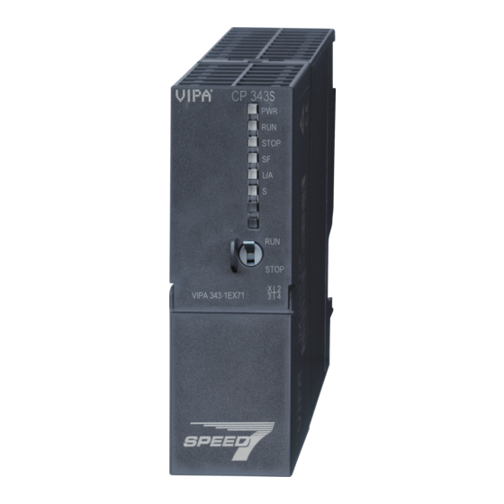
CP | 343-1EX71 | Manual
HB140 | CP | 343-1EX71 | GB | 16-42
SPEED7 CP 343S-NET
Table of
Contents
Previous
Page
Next
Page
1
2
3
4
5
Advertisement
Table of Contents
Need help?
Do you have a question about the System 300S and is the answer not in the manual?
Ask a question
Questions and answers
Related Manuals for VIPA System 300S
Control Systems VIPA System 300S Manual
Hb140 (228 pages)
Network Hardware VIPA System 300S Manual
(182 pages)
Controller VIPA SPEED7 CPU 312-5BE13 Manual
(180 pages)
Control Unit VIPA System 300S Manual
(179 pages)
Control Systems VIPA SPEED7-SPU 315-4PN12 Manual
(168 pages)
Control Unit VIPA System 300S Manual
Sm-aio (165 pages)
Computer Hardware VIPA System 300S Manual
(148 pages)
Controller VIPA System 300S Manual
Speed7 - cpu; 314-2ag13 (148 pages)
Control Systems VIPA System 300S Manual
Speed7 - cpu, 314-2bg03 (122 pages)
Control Unit VIPA System 300S Manual
Speed7 - cp 342-2ia71 (74 pages)
Controller VIPA System 300S Manual
Vipa system 300s speed7 (56 pages)
Control Unit VIPA System 300S SPEED7 CPU 313SC/DPM Manual
(152 pages)
Control Unit VIPA CPU 315-4PN43 Manual
(179 pages)
Control Unit VIPA System 300S IM 353-1DP01 Manual
(52 pages)
Control Unit VIPA IM 306-1LZ00 Manual
(58 pages)
Control Unit VIPA 313-6CF03 Manual
(152 pages)
This manual is also suitable for:
Cp 343-1ex71
Table of Contents
Print
Rename the bookmark
Delete bookmark?
Delete from my manuals?
Login
Sign In
OR
Sign in with Facebook
Sign in with Google
Upload manual
Upload from disk
Upload from URL


Need help?
Do you have a question about the System 300S and is the answer not in the manual?
Questions and answers