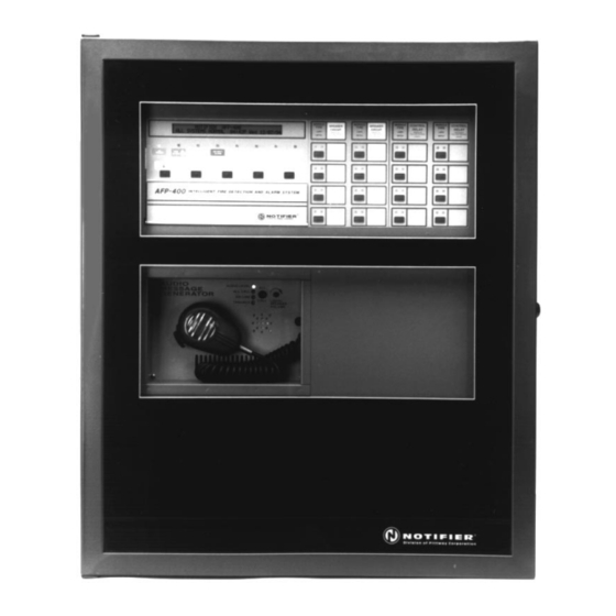
Notifier AFP-400 Installation Manual
Analog fire panel
Hide thumbs
Also See for AFP-400:
- Programming manual (48 pages) ,
- Product installation manual (2 pages) ,
- Installation manual (207 pages)
Table of Contents
Advertisement
Advertisement
Table of Contents

Related Manuals for Notifier AFP-400


Summary of Contents for Notifier AFP-400
-
Page 2: Installation Precautions
Installation Precautions Adherence to the following will aid in problem-free installation with long-term reliability: WARNING - Several different sources of power can be connected to Like all solid state electronic devices, this system may operate this fire alarm control panel. Disconnect all sources of power before erratically or can be damaged when subjected to lightning induced servicing. - Page 3 Continued on the next page...
- Page 4 Continued on the next page...
- Page 5 Continued on the next page...
-
Page 26: Installation
2. Installation... - Page 34 Mounting Modules in the Chassis...
- Page 37 Connecting the MPS-400...
-
Page 49: Field Wiring The Modules
Field Wiring the Modules... - Page 50 Terminal Assignments for Module Control of the ARM-4...
-
Page 59: Power Supply Calculations
Power Supply Calculations... - Page 61 Calculation Column 1 Calculation Column 2 Calculation Column 3 Primary, Non-Fire Alarm Primary, Fire Alarm Current Secondary, Non-Fire Alarm Current (amps) (amps) Current (amps) Category X [current total X [current draw]= total X [current draw]= total draw]= Basic system 0.225 0.420 0.170 (CPU-400 + MPS-400)
-
Page 64: Power Connections
Power Connections 1 2 3 4 5 6... -
Page 65: Output Circuits
Output Circuits... - Page 75 ISO-X ISO-X...
- Page 76 Wiring an Isolator Module (ISO-X)
- Page 77 MMX Monitor Modules...
-
Page 90: Testing The System
3. Testing the System... - Page 91 Testing the System DANGER...
- Page 99 AU DIO PA GE MOD E O N L I N E FIRE PA G E FIGHTERS P HO NE L INE T ROUB LE TELEPHONE T R OU BL E...
- Page 116 ○ ○ ○ ○ ○ ○ ○ ○ ○ ○ ○ ○ ○ ○ ○ ○ ○ ○...
- Page 117 ○ ○ ○ ○ ○ ○ ○ ○ ○ ○ ○ ○ ○ ○ ○ ○ ○ ○...
- Page 118 ○ ○ ○ ○ ○ ○ ○ ○ ○ ○ ○ ○ ○ ○ ○ ○ ○ ○...
- Page 127 5. Applications...
-
Page 131: Network Interface Board
Network Interface Board... -
Page 133: Board Description
UZC-256 Board Description... - Page 134 Using the XP Transponder with the AFP-400...
- Page 135 Combination Fire/Burglary Applications...
- Page 138 Zone Coding with the UZC-256 UZC-256 UZC-256 CHS--4...
- Page 139 Zone Coding, continued...
- Page 140 Zone Coding, continued...
- Page 141 Zone Coding, continued...
- Page 148 Input System Alarm System Trouble Acknowledge Output Not Used Signal Silenced Signal Silence Output Not Used Program Mode System Reset Output Not Used Supervisory Drill Output NAC #1 Active NAC Trouble Control NAC #1 Input Not Used PA/Maint Alert Not Used Input Not Used Low Battery...
- Page 149 Input Zone 57 Active Zone 57 Trouble Not Used Input Zone 58 Active Zone 58 Trouble Not Used Input Zone 59 Active Zone 59 Trouble Not Used Input Zone 60 Active Zone 60 Trouble Not Used Input Zone 61 Active Zone 61 Trouble Not Used Input...
- Page 150 Input or Output Module 101 Active Module 101 Trouble Controls Output Module Input or Output Module 102 Active Module 102 Trouble Controls Output Module Input or Output Module 103 Active Module 103 Trouble Controls Output Module Input or Output Module 104 Active Module 104 Trouble Controls Output Module Input or Output...
- Page 151 Input or Output Module 201 Active Module 201 Trouble Controls Output Module Input or Output Module 202 Active Module 202 Trouble Controls Output Module Input or Output Module 203 Active Module 203 Trouble Controls Output Module Input or Output Module 204 Active Module 204 Trouble Controls Output Module Input or Output...
- Page 152 Input or Output Module 165 Active Module 165 Trouble Controls Output Module Input or Output Module 166 Active Module 166 Trouble Controls Output Module Input or Output Module 167 Active Module 167 Trouble Controls Output Module Input or Output Module 168 Active Module 168 Trouble Controls Output Module Input or Output...
- Page 153 Input Detector 101 Alarm Detector 101 Trouble Not Used Input Detector 102 Alarm Detector 102 Trouble Not Used Input Detector 103 Alarm Detector 103 Trouble Not Used Input Detector 104 Alarm Detector 104 Trouble Not Used Input Detector 105 Alarm Detector 105 Trouble Not Used Input...
- Page 154 Input Detector 201 Alarm Detector 201 Trouble Not Used Input Detector 202 Alarm Detector 202 Trouble Not Used Input Detector 203 Alarm Detector 203 Trouble Not Used Input Detector 204 Alarm Detector 204 Trouble Not Used Input Detector 205 Alarm Detector 205 Trouble Not Used Input...
- Page 155 Input Detector 165 Alarm Detector 165 Trouble Not Used Input Detector 166 Alarm Detector 166 Trouble Not Used Input Detector 167 Alarm Detector 167 Trouble Not Used Input Detector 168 Alarm Detector 168 Trouble Not Used Input Detector 169 Alarm Detector 169 Trouble Not Used Input...
- Page 156 Output Module P1.1 Active Module P1.1 Trouble Controls Module P1.1 Output Module P1.2 Active Module P1.2 Trouble Controls Module P1.2 Output Module P1.3 Active Module P1.3 Trouble Controls Module P1.3 Output Module P1.4 Active Module P1.4 Trouble Controls Module P1.4 Output Module P1.5 Active Module P1.5 Trouble Controls Module P1.5...
- Page 157 + – + – In Out...
- Page 161 (–)
-
Page 162: Appendix B: Wire Requirements
Appendix B: Wire Requirements... -
Page 163: Appendix C: Compatible Equipment
Appendix C: Compatible Equipment... - Page 165 Appendix D: CRT-2 Configuration...
- Page 166 CRT-2 Configuration...
- Page 167 Appendix E: Terminal Interface Protocol...
- Page 168 Operating Modes, continued...
-
Page 169: Using The Crt-2 For Read Status
Using the CRT-2 for Read Status... - Page 170 Using the CRT-2 for Read Status, continued...
- Page 171 Using the CRT-2 for Read Status, continued...
- Page 172 Using the CRT-2 for Read Status, continued...
-
Page 173: Using The Crt-2 For Alter Status
Using the CRT-2 for Alter Status... - Page 174 Using the CRT-2 for Alter Status, continued...
- Page 175 Using the CRT-2 for Alter Status, continued...
-
Page 176: Appendix F: Ul Power Limited Wiring Requirements
Appendix F: UL Power Limited Wiring Requirements... - Page 177 UL Power Limited Wiring Requirements...
- Page 178 UL Power Limited Wiring Requirements...
-
Page 179: Limited Warranty
® manufacturing date-stamp control, the warranty ® is eighteen (18) months from date of original purchase by NOTIFIER 's distributor unless the installation instructions or catalog sets forth a shorter period, in which case the shorter period shall apply. This warranty is void if the product is altered, ®...
Need help?
Do you have a question about the AFP-400 and is the answer not in the manual?
Questions and answers