Table of Contents
Advertisement
Quick Links
Advertisement
Table of Contents

Subscribe to Our Youtube Channel
Related Manuals for Datavideo TVS-1200A


Summary of Contents for Datavideo TVS-1200A
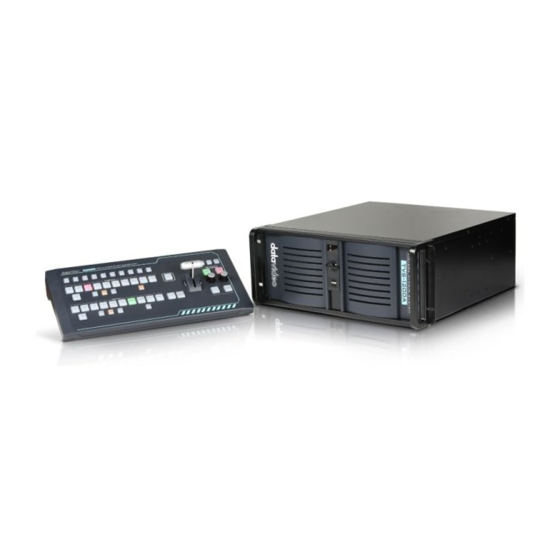
- Page 1 TRACKLESS VIRTUAL STUDIO SYSTEM TVS-1200A Instruction manual...
-
Page 2: Table Of Contents
ARRANTY ............................5 HREE ARRANTY DISPOSAL ................................5 CHAPTER 1 OVERVIEW ..........................7 ............................... 7 EATURES CHAPTER 2 TVS-1200A TRACKLESS VIRTUAL STUDIO SETUP ................. 9 ..........................9 YSTEM EQUIREMENT ............................. 9 YSTEM IAGRAM ............................10 ONNECTIONS 2.3.1 Front Panel ..........................10 2.3.2... - Page 3 Datavideo Technologies is not responsible for any omissions or errors, or for any subsequent loss or damage caused by using the information contained within this manual. Further advice on the content of this manual or on the product can be obtained by contacting your local Datavideo Office or dealer.
-
Page 4: Fcc Compliance Statement
AC adapter. If you are not sure of the type of power available, consult your Datavideo dealer or your local power company. 8. Do not allow anything to rest on the power cord. Do not locate this unit where the power cord will be walked on, rolled over, or otherwise stressed. -
Page 5: Warranty
PCIe Card are covered for 1 year. The three-year warranty must be registered on Datavideo's official website or with your local Datavideo office or one of its authorized distributors within 30 days of purchase. Disposal For EU Customers only - WEEE Marking This symbol on the product or on its packaging indicates that this product must not be disposed of with your other household waste. - Page 6 CE Marking is the symbol as shown on the left of this page. The letters "CE" are the abbreviation of French phrase "Conformité Européene" which literally means "European Conformity". The term initially used was "EC Mark" and it was officially replaced by "CE Marking" in the Directive 93/68/EEC in 1993.
-
Page 7: Chapter 1 Overview
Furthermore, with two camera inputs and two keyers, the TVS-1200A gives the user the capability to place two talents on one virtualset. The TVS-1200A can also be used in a remote scenario whereby the images captured by the two cameras at two different sites are placed on one single virtualset. - Page 8 PROGRAMME – presentation of the current programme broadcast (system output); Previews on multiple monitors (if monitors are connected to a workstation, it is possible to obtain different preview configurations, even on three monitors). Supported Formats Format: 720p50 – image resolution: 1280 x 720 ...
-
Page 9: Chapter 2 Tvs-1200A Trackless Virtual Studio Setup
Chapter 2 TVS-1200A Trackless Virtual Studio Setup System Requirement Monitor x 1 (up to three monitors connected to choices of the HDMI x 1, DVI x 1, DisplayPort x 3) Keyboard SDI camera x 2 System Diagram... -
Page 10: Connections
Connections 2.3.1 Front Panel The front panel contains the RS-232 connection for operation with an external Datavideo RMC-220 control panel. Access to the front panel is protected with a keyed door. This provides protection against the system being accidentally switched off or reset or the data disk being removed. -
Page 11: Input/Output Card Options
Removable Hard Disk Installation This section shows you how the 2.5" HDD in Removable Rack can be assembled. Warning: You must use the TVS-1200A proprietary HDD and not any Datavideo HDR series or DN series. Avoid HOT PLUGGING during operation (while writing to and reading from the disk) because it may cause damage to the system and files. -
Page 12: Rmc-220 Remote Controller
RMC-220 Remote Controller The RMC-220 is a cost effective remote controller designed specifically for the TVS-1200A Virtual Studio System. The RMC-220 interfaces with the TVS-1200A Virtual Studio System via an RS-232 interface. The RMC-220 gives the user switcher-style control of the TVS-1200A Virtual Studio System. -
Page 13: Control Panel Overview
Capture function records the live video program Still Grab function captures the instantaneous video image RS-232 interface for communication between RMC-220 and TVS-1200A 12V DC input making the unit ideal for studio applications Bright LED lighting 2.5.1 Control Panel Overview... -
Page 14: Main Unit - Rear Panel
Still 2 Still Picture 2 selection DSK 2 DSK 2 and source assignment knob AUX Card Input selection Placement of DSK on Program Phase 1 Phase 1 selection Fade Gradual placement of DSK Phase 2 Phase 2 selection 2.5.2 Main Unit - Rear Panel RS-232: RS-232 Communication Interface DC 12V: 12V DC Power Input... -
Page 15: Downstream Keyers
T-Bar This performs a manually controlled transition from the current program source to the selected preset source. When the T-Bar has travelled as far as it can go, the transition between sources is complete. 2.5.5 Downstream Keyers DSK 1/2 Pressing DSK 1/2 places logo or animations on the program view. Before placing the DSK on the program view, make sure it is correct on the PVW screen first. -
Page 16: Keyboard Backlight
Capture Record the current live video program and save automatically to the hard disk. Still/Grab Capture a frame of video and save automatically to the hard disk. 2.5.7 Keyboard Backlight The RMC-220 allows the user to manually adjust the keyboard backlight. The steps are outlined as follows: 1. -
Page 17: Specifications
2.5.9 Specifications Communication Interface RS-232 Baud Rate 38400 ODD Power DC12V ± 25% Power Consumption Working Temperature 0°C ̴ +40°C Storage Temperature -20°C ̴ +60°C Relative Humidity ≤ 90% (non-condensation) Dimensions Refer to Page 10 Net Weight 1.28Kg RS-232 Transmission Cable Accessories DC In Power Adaptor... -
Page 18: Chapter 3 Starting Tvs-1200A Software
2. Connect one or multiple monitors to TVS-1200A via HDMI, DVI and Display Port. 3. Press the power button to boot the TVS-1200A hardware system. Power button is located on the right of the red reset button; refer to the... -
Page 19: Production Live
The Virtualset Maker can also be used as a standalone application on the PC, and may be downloaded from http://www.datavideo.com/TVS-Virtualsetmaker. The PC needs to meet the minimum system requirements as described below: CPU: i3 Processor or faster ... -
Page 20: Tvs News Link
TVS News Link The TVS News Link feature allows Datavideo to publish updated information to the user. The information can be in the form of blog entries, news headlines, audio or video. VIRTUALSET Shop If the user would like to... - Page 21 How to download free sets if you already have an account on http://www.datavideovirtualset.com/? On the TVS-1200A main screen, select configuration then click the “Free Sets.” Enter your email address then click “download free sets.” Please be patient while downloading.
-
Page 22: Shutdown
Shutdown To exit the startup panel, the user can simply click on the “Close application” button or the “Shutdown system” button to shut down the system. Note: A popup warning dialogue box will appear as shown below after you click on the “Close application”... -
Page 23: Chapter 4 Virtualset Maker
.dvsx virtualset file format readily available for use in the Production Live Module of TVS-1200A Available in four different languages: English, Simplified Chinese, Traditional Chinese and Japanese Three talent shot settings: full body, half body or desk shot Editing of the virtualsets downloaded from Datavideo’s virtual set database (http://www.datavideovirtualset.com/) -
Page 24: Getting Started
Getting Started On desktop of the TVS-1200A Virtual Studio System, double click the TVS-1200A icon on the desktop to start the system and bring up the startup page as shown below. Start-up Screen Locate and click on to open VIRTUALSET Maker. However, before you start, select a proper resolution first from the pull-down menu on the left of the “Start Maker”... -
Page 25: Virtualset Maker Tour
Pane 1 is the preview area that allows you to view all modifications made to the virtualset. Pane 2 contains the order of all layers, where you can define their relationships in a virtualset. Pane 3 is the controller part, which are tools for zoom, rotation and file change of the layers. VirtualSet Maker Tour On the menu bar of Virtualset Maker, you will find four options: File, Edit, Configuration and Help. - Page 26 Please note that the suggested resolution of the studio layer is 2880 x 1620 (16:9). This is the standard virtualset resolution in the TVS-1200A. You can of course use other resolutions but you will need to fine-tune your image later.
- Page 27 Click to make a particular layer Eyes visible in the editor Click on this button to hide all Solo other layers except selected layer object At the bottom left hand corner of Virtualset Maker, there are various options available user manipulate the layers (While Studio layer is selected, some image layer options will be disabled).
- Page 28 3 are enabled. The example below illustrates how you can zoom, rotate and position a “datavideo” logo using the five controllers outlined as follows. The goal is to pave the studio layer with the datavideo logo.
- Page 29 The logo can be flipped along the x-axis. Knob for rotation along x-axis The logo can be flipped along the y-axis. Knob for rotation along y-axis...
- Page 30 Knob for rotation along z-axis Finally, use the position knob to move the datavideo logo to the desired position and the zoom slide bar to fine-tune the logo to the appropriate size. The diagram below shows you the final work with the floor covered with datavideo logo.
- Page 31 Screen area is where the video or picture are placed after program starts. Adjust and move the green rectangular screen to the respective desired size and position using the controllers in pane 3. In addition, the screen size and shape can also be adjusted by pulling or dragging the four corners.
- Page 32 (Source A and Source C), only one talent will appear on the TVS- 1000A system. The TVS-1200A supports two talent layers (Source A and Source C), but if your virtualset is designed for the one-talent scenario (Source A), only one talent will appear on the TVS-1200A system.
- Page 33 After everything is in place, fine-tune your talent layer size and move the talent layer to the desired position. Finally, save your virtualset on the disk, and remember that checking “Mark set as not writable” applies overwrite protection to the set. After the virtualset is saved, close VIRTUALSET Maker, and import the virtualset to the Production Live Module to start your own virtual studio tour.
-
Page 34: Chapter 5 Production Live Screen
Chapter 5 Production Live Screen After entering the production live option, the production screen will appear as illustrated in the diagram below. The production screen can generally be divided into five areas: 1. Tool Bar 2. Multi-View Screens 3. Switcher-like Buttons 4. - Page 35 The user is allowed to select among three languages listed as follows: English Simplified Chinese Traditional Chinese Japanese Help About: Clicking About displays information such as EULA, Version number, and Serial Number QR Code: Scan the QR code to download TVS-1200A User Manual...
-
Page 36: Multi-View Area
Multi-View Area In the multi-view area, the user is able to view the camera source and other multiple multimedia file sources on the left-hand side of the area. There are two screens on the right- hand side: PREVIEW and PROGRAMME. •... -
Page 37: 10-Input Main Switcher
Program and Preview Rows are production switcher style buttons. The user is able to switch between different sources displayed on the Preview and Program screens by clicking on the corresponding buttons. 5.3.1 10-input Main Switcher 2 x CAM – enables two camera sources and the chroma and luma keying functions can be applied to the signals on this channel. -
Page 38: Downstream Keys
5.3.3 Downstream Keys Next to the 10-input main switcher is the downstream key (DSK) block. It can be used to add images or text to the broadcast signal. DSK signal may come from any virtual player that displays media (1 or 2), bitmaps (1 or 2), or text (1 or 2). It may also come from the camera inputs. -
Page 39: Virtual Background Editing
Joystick: Logo positioning Center Roller: Logo scaling Adjustment Knob: Logo rotation (Still Text and Picture only) After the logo to be placed on the program view is properly configured, the next step is to place the logo on the program view. Click on CUT/Fade buttons to switch the key between Preview and Program screens and the button will turn red. -
Page 40: Import
Preview of the selected virtualset is available on the right of the directories listing window. Choose the desired dvsx file to the selected M/E bin. Click on M/E1-4 tabs to view the corresponding loaded virtual studios on Preview window of the Multi-View Area. File Location: D:/TVS-1200A Data/Sets/... -
Page 41: Placement
5.4.2 Placement Phase is defined as the virtual camera position in a virtual studio. Each virtual scene (M/E1 – M/E4) can be assigned three phases (phase 1 – 3). Click on any of the three phase windows to configure the image phase settings. The current phase is highlighted with an orange bar above the preview window as shown in the diagram below. -
Page 42: Auto Play
the changes. Click the “Close” button to shut down the “Placement Configuration Window” after you have configured the desired placement settings. 5.4.3 Auto Play Auto Play generates the animated PTZ transition effect. If the AutoPlay function is switched on, the camera movement is smooth, animated. The transition time is adjusted by controls located on the right of the phase previews (Time, Frame). -
Page 43: File Management
Production Live module. File Management The TVS-1200A allows the user to apply videos and still images to the program window. The file management system is designed to serve this purpose by allowing the user to do all the preparation work before the broadcast. - Page 44 In each specific tab, the user can also divide the content (files) into five categories (maximum). This is done by means of sections (designated 1 to 5). The sections can be used to keep files in order, for specific activities. The use of media requires two actions: •...
- Page 45 Buttons in the lower part of the Media Bin are used to control the file played in the player. The available functions are: Play , Pause , Stop , and Loop (Loop is on by default). The playback progress bar, information on the video length and the current playback position are also shown.
- Page 46 Navigate through the categories by clicking on buttons 1 to 5 located on the right of the file display area. The formats supported for bitmap files (for media added to the TEXT1 and TEXT2 tabs) are: PNG (with transparency) TVS-1200A STILL (own STILL TEXT edit module)
-
Page 47: Additional Monitor Support
Hence, in order to allow the user to manage multiple monitors, a Monitor Configuration Interface as shown in the diagram below is built into the TVS-1200A. To open the interface, simply click “Configuration” on the tool bar, select “Configuration” option and then click... -
Page 48: General Display And Audio Settings
Program View, i.e., the Program view image is flipped along the y-axis. In addition, the TVS-1200A is able to output PGM audio on the selected sound card. To hear the PGM audio, follow the steps outlined below to configure your system setup. - Page 49 Two other additional things can be configured in the Motherboard Audio Output section: Gain: The Gain sliding bar is used for audio volume adjustment, which is set to the maximum level by default. Delay: By sliding the Delay bar to the right you are adding delay to the audio line which synchronizes the audio to the video if the video display device (typical LCD TV) generates delay.
-
Page 50: Chapter 6 Chroma And Luma Keys
Chapter 6 Chroma and Luma Keys Keying is a special filter that the TVS-1200A uses to remove a specific color (e.g. Green) from the image by applying the filter to the input CAM. CH/L Key 1 applies the filter to the input CAM 1 and CH/L Key 2 applies the filter to the input CAM 2. -
Page 51: Matte Control
If the colour of the keyed out background is not uniform, the user can make use of the Detect Color button, which will calculate the background’s LRGB parameters using the automated average. If the parameters cannot be accessed, the user will be notified about it via a message window, after which the colour will be reset to default. - Page 52 The Show alpha matte view The intended result is to make the mask background colour as close to perfect black as possible. In order to do that the Black Level slider should be moved until black is distributed as evenly as possible on the mask background. A view after a Black level adjustment If the slider is moved to the extremes, the other objects will lose their properties and become non-transparent;...
-
Page 53: Tolerance Correction
A view after a White level adjustment In many cases, the option White Level will be used in conjunction with the option Black Level in order to obtain the most possible effective settings of the black background, with no loss on white objects and vice versa. - Page 54 The second function is called Color and its use leads to the restoration to a uniform black structure of the background. It improves in particular the visibility of an object in the case of a significant difference in luminance between the background and the object. This means that semi-transparent objects, e.g.
-
Page 55: Spill Correction
Spill Correction Spill correction removes keying colour remains (Despill). Once the correct mask is set, the functions in the Spill correction section will eliminate the reflection of the colour of the keyed background in the object. Impact of the background colour on the object – a view before a Despill correction Click on the Spill Correction button to enter the setting page. - Page 56 Once the Despill color slider is moved to position 0 (the left-hand side), the algorithm will automatically remove the green colour component if this is the keyed colour (similarly – blue if the background is blue). Once the Despill color slider is moved to position 1000 (the right- hand side), however, the algorithm will automatically add the red colour and the blue colour (if the keyed colour is green) or red and green (if the background is blue).
-
Page 57: Edge Correction
Impact of the background on the object – a view after a Despill correction Edge Correction Additional correction is applied to improve quality. Click on the Edge Correction button enter the setting screen. The Edge Correction function is used to correct semi-transparent areas (e.g. hair ends that need to be darkened or brightened) in order to make an object look natural. - Page 58 The Garbage mask section This function is used if the view of the keyed background is not large enough to fill in the entire object shot. A view from the camera area By cutting the remaining elements by means of the sliders Left, Right, Top, Bottom, it is possible to place the object within the area of the keyed background.
- Page 59 A view after a Garbage mask correction with the keying algorithm switched off After enabling the chroma keying function, the following effect is obtained. A view after the Garbage mask correction with the keying algorithm switched on Comments: It should be kept in mind that in this case the object may only move within the area of the cut off mask –...
-
Page 60: Post Correction
Post Correction Post Correction matches the object to the conditions of the virtual background. The following functions illustrated in the diagram below are used for post-correction of the object and have no effect on its virtual background. Brightness – this enables additional colour brightness to be introduced into the picture. Contrast –... -
Page 61: Chapter 7 Fast Chromakeying
Chapter 7 Fast Chromakeying The TVS-1200A comes with two special features that allow the user to perform fast chromakeying. The two special features are Simple Chroma Key and the Wizard. Simple Chroma Key Simple Chroma Key mode gives the user the capability to apply the chromakeying effect with a single mouse click. - Page 62 Chapter 8 Sound mixer The TVS-1200A comes equipped with a sound mixer function, which is responsible for mixing sound signals. It also allows the user to adjust the signal level for each source and separately for the sound output. The sound mixer allows the user to adjust the following channels: ...
-
Page 63: Chapter 9 Motion Capture Specification
Chapter 9 Motion Capture Specification The TVS-1200A uses Intel® Quick Sync Video technology, which is a built-in feature in some of Intel processors. It allows hardware acceleration of video stream encoding. The TVS-1200A also supports capturing of system PGM output. This enables the use of the TVS-1200A as a video recorder and is usually used in live production. - Page 64 In addition to program video recording, the user can also grab instantaneous images on the Program view by clicking on the STILL/GRAB button. The grabbed images are saved in PGN format. The grabbed images will be added to section 5 of both Still tabs of the Media Bin (Still 1 or Still 2) shown below.
-
Page 65: Chapter 10 Program Video Stream
As a result, live programs can reach all viewers in real time, even in remote areas. The TVS-1200A is the main element for such realization because in addition to creating a broadcast signal, it is also capable of converting the broadcast signal into a network data stream. -
Page 66: Chapter 11 External Keyboards
Chapter 11 External Keyboards The user is allowed to control the TVS-1200A with external keyboards such as an RMC-220 Remote Controller and a standard keyboard. Details of each are outlined in the following sections. 11.1 RMC-220 Function Keys There are 10 user-defined function keys, F1 to F10, on RMC-220 Remote Controller. These function keys are configurable on the TVS-1200A system. -
Page 67: Advanced
11.1.1 Advanced In Advanced mode, the user is allowed to select all available functions in the above table. Furthermore, the execution sequence of the selected functions is customizable. Select “Advanced” and Click on to open a command selection window shown below. Select a function, for example, “DSK: Set Source #1”... -
Page 68: Simple
After all the desired functions are selected, click on the next key tab and repeat the above until all keys are assigned the functions that you desire. 11.1.2 Simple If the user’s selection is “Simple” Mode, a user interface will appear as shown in the diagram below. -
Page 69: Chapter 12 System Recovery
Chapter 12 System Recovery The TVS-1200A also offers the user a system recovery mechanism when the system is unstable. Reboot the TVS-1200A and during the system boot-up process, select the DriveClone System Recovery option to enter the recovery process when the screen below appears. This recovery process resets C drive to factory default but keeps the data on D drive. - Page 70 Select the appropriate recovery option and click on the Start button Wait till the progress bar shows 100% completion...
- Page 71 Once the recovery process is finished, click on OK button to trigger system reboot...
-
Page 72: Chapter 13 Frequently-Asked Questions
Chapter 13 Frequently-Asked Questions This section describes problems that you may encounter while using the TVS-1200A. If you have questions, please refer to related sections and follow all the suggested solutions. If problem still exists, please contact your distributor or the service center. - Page 73 I cannot hear audio output from the If your output is set to 1080P 50/60, please TVS-1200A PGM OUT while the make sure the SDI 3G output mapping output is set to 1080P 50/60, (Configuration / Configuration / General) is however, I can see the video.
-
Page 74: Specifications
Chapter 14 Specifications Model Name TVS-1200A Product Name Trackless Virtual Studio System Tracking/Trackless Trackless Video Input 3G-SDI x 2 + AUX-HDMI x 1 Video Output 3G-SDI x 2 + AUX-HDMI x 1 Video 1080p 60/59.94/50/30/29.97/25 Input/Output 1080i 60/59.94/50 Format 720p 60/59.94/5... -
Page 75: Chapter 15 Tvs-1200A Aux Card (Optional)
TVS Virtu AUX Card is designed primarily for powerpoint file input via HDMI port as well as for other applications such as media player or camera input. TVS AUX card can also be used in the TVS-1200A. The TVS Virtu AUX Card is an optional component for the TVS-1200A. 15.2 Installation 1. -
Page 76: Service & Support
Sept.-12.2018 Version E2...
Need help?
Do you have a question about the TVS-1200A and is the answer not in the manual?
Questions and answers