Advantech PCA-6751 series Manual
Half-size all-in-one pentium cpu card with mmx cpu vga/lcd and fast ethernet interface
Hide thumbs
Also See for PCA-6751 series:
- User manual (111 pages) ,
- Startup manual (4 pages) ,
- User manual (113 pages)
Table of Contents
Advertisement
Quick Links
Download this manual
See also:
User Manual
Advertisement
Table of Contents

Subscribe to Our Youtube Channel
Related Manuals for Advantech PCA-6751 series


Summary of Contents for Advantech PCA-6751 series
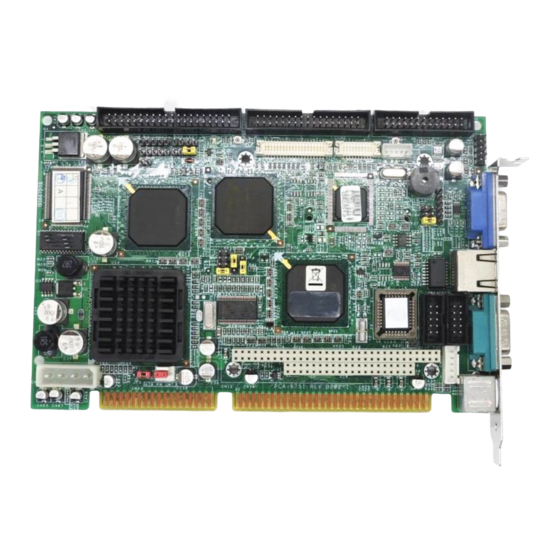
- Page 1 PCA-6751 series ® Half-size all-in-one Pentium card with MMX CPU, VGA/LCD and Fast Ethernet interface...
-
Page 2: Copyright Notice
UMC is a trademark of United Microelectronics Corporation. All other product names or trademarks are properties of their respective owners. For more information on this and other Advantech products please visit our web sites at: http://www.advantech.com http://www.advantech.com/epc For technical support and service for please visit our support web site at: http://support.advantech.com... -
Page 3: Packing List
Packing List Before installing your board, ensure that the following materials have been received: • 1 PCA-6751/6751V all-in-one single board computer • 2 utility disks with Ethernet utility programs • 430 TX chipset driver for Windows 95 • 3 utility disks with SVGA utility programs and drivers for Windows 3.1/95/98/NT •... -
Page 4: Table Of Contents
Contents Chapter 1 Hardware Configuration Introduction ...............2 ® Embedded Pentium MMX CPU ........2 Guaranteed long product supply time .........2 Specifications ..............3 Standard SBC functions ............3 VGA function ..............3 Ethernet controller functions (PCA-6751 only)....4 Solid state disk ..............4 Mechanic and environmental specifications .......4 Board Layout: Dimensions ..........5 Safety Precautions .............6 Jumper Settings ..............7... - Page 5 2.12 Watchdog Timer PROG (CN10) ........20 2.13 VGA Display Connector (CN11) ........20 2.14 PC-104 Connectors (CN12) ..........20 2.15 Ethernet Configuration (CN13 PCA-6751 only) ..20 2.15.1 RJ-45A connector (CN13) ........20 2.15.2 Network boot ............20 2.16 Serial Ports (CN16: COM1; CN15: COM2/RS-232; CN14: COM2/RS-422/485) ..........21 2.17 External Keyboard (CN17) ..........22 2.18 ATX Power Connector (CN18) ........22...
- Page 6 Chapter 4 PCI SVGA Setup Introduction ..............40 Chipset ................40 Display memory ...............40 Installation of SVGA Driver ..........41 4.2.1 Installation for Windows 3.1 .........42 4.2.2 Installation for Windows 95 ........44 4.2.3 Installation for Windows NT .........47 Further Information ............49 Chapter 5 PCI Bus Ethernet Interface (PCA-6751 only) Introduction ..............52 Installation of Ethernet Driver ........52...
- Page 7 Appendix C Pin Assignments Floppy Drive Connector (CN1) ........68 Parallel Port Connector (CN2) ........69 Keyboard Lock Connector (CN3) .........70 USB1/USB2 Connector (CN4) ........70 24-bit LCD Display Connector (CN5) ......71 36-bit LCD Display Connector (CN6) ......72 LCD Power Inverter (CN7) ..........72 IR Connector (CN8) ............73 External Speaker Connector (CN9) ......73 C.10 CRT Display Connector (CN11) ........74...
- Page 8 Tables Table 1-1: COM2 settings for RS-232/422/485 (JP1) ........8 Table 1-2: LCD panel select (JP2) ..............9 Table 1-3: RTC power and CMOS clear (JP3) ..........10 Table 1-4: Watchdog timer system reset select (JP4) ........11 Table 2-1: Connectors ..................16 Table 2-2: Serial port connections (COM1, COM2) .........
- Page 9 Figures Figure 1-1: Board layout: dimensions ............... 5 Figure 3-1: Setup program initial screen ............28 Figure 3-2: CMOS setup screen ..............29 Figure 3-3: BIOS features setup screen ............30 Figure 3-4: CHIPSET features setup screen ............ 34 Figure 3-5: Power management setup screen ..........35 Figure 3-6: PCI configuration screen ..............
- Page 10 PCA-6751/6751V User's Manual...
-
Page 11: Chapter 1 Hardware Configuration
Hardware Configuration This chapter gives background information on the PCA-6751/6751V. It shows you how to configure the card to match your application and prepare it for installation into your PC. Sections include: • Card specifications • Board layout: dimensions • Board layout: jumper locations •... -
Page 12: Introduction
Introduction The PCA-6751/6751V is a half-size ISA-bus CPU card designed with ® an on-board Intel Pentium MMX CPU. Featuring powerful on-board functions such as VGA, LCD, LAN and SSD, the versatile PCA-6751/6751V can meet the needs of different applications. ® Embedded Pentium MMX CPU The PCA-6751/6751V is equipped with Intel's new embedded... -
Page 13: Specifications
Specifications Standard SBC functions ® • CPU: Intel Pentium MMX CPU 166/266 MHz • BIOS: AWARD 2 Mbit Flash BIOS, supports Plug & Play, APM 1.2, Ethernet boot ROM, boot from CD-ROM, LS-120, and ZIP drive • Chipset: Intel 430 TX •... -
Page 14: Ethernet Controller Functions (Pca-6751 Only)
Ethernet controller functions (PCA-6751 only) • Controller: Intel SB82558. 10 Mbps / 100 Mbps • I/O address switchless setting • Connector type: RJ-45 • Boot ROM: Built-in system (optional) Solid state disk • Supports Compact Flash disks Mechanic and environmental specifications •... -
Page 15: Board Layout: Dimensions
Board Layout: Dimensions 185.00 161.44 157.44 155.13 111.95 109.84 108.53 106.47 104.04 103.45 101.84 102.18 99.64 81.86 54.17 25.98 25.64 23.44 23.44 18.36 15.44 13.82 12.03 7.23 7.62 8.48 5.00 4.00 0.00 Unit: mm Figure 1-1: Board layout: dimensions Chapter 1 Hardware Configuration... -
Page 16: Safety Precautions
Safety Precautions Follow these simple precautions to protect yourself from harm and your PC from damage. 1. To avoid electric shock, always disconnect the power from your PC chassis before you work on it. Don't touch any components on the CPU card or other cards while the PC is on. -
Page 17: Jumper Settings
Jumper Settings This section tells how to set the jumpers to configure your card. It gives the card default configuration and your options for each jumper. After you set the jumpers and install the card, you will also need to run the BIOS Setup program (discussed in Chapter 3) to configure the serial port addresses, floppy/hard disk drive types and system operating parameters. -
Page 18: Com2 Settings For Rs-232/422/485 (Jp1)
1.5.1 COM2 settings for RS-232/422/485 (JP1) Table 1-1: COM2 settings for RS-232/422/485 (JP1) *RS-232 RS-422 RS-485 * default setting 1.5.2 LCD panel select (JP2) PCA-6751/6751V User's Manual... -
Page 19: Table 1-2: Lcd Panel Select (Jp2)
Table 1-2: LCD panel select (JP2) LCD type LCD type 1024 x 600 TFT 800 x 600 TFT 48 K 800 x 600 DSTN2 800 x 600 DSTN 48 K 1280 x 1024 DSTN 640 x 480 TFT 48 K 18-bit 800 x 600 TFT 2 1280 x 1024 TFT... -
Page 20: Cmos Backup Select (Jp3)
1.5.3 CMOS backup select (JP3) Warning: To avoid damaging the computer, always turn off the power supply before setting "Clear CMOS". Set the jumper back to normal before turning on the power supply. Table 1-3: RTC power and CMOS clear (JP3) *Normal CMOS data clear * default setting... -
Page 21: Watchdog Timer Configuration (Jp4)
1.5.4 Watchdog timer configuration (JP4) An on-board watchdog timer reduces the chance of disruptions caused by EMP (electro-magnetic pulse) interference. It is an invaluable protective device for standalone or unmanned applications. Setup involves two jumpers and running the control software. (Refer to Appendix A.) When the watchdog timer is enabled and the CPU shuts down, the watchdog timer will automatically either reset the system or generate... -
Page 22: Installing System Memory (Sodimms)
Installing System Memory (SODIMMs) You can install anywhere from 8 to 256 MB of SDRAM into your PCA-6751/6751V card. The card provides two 144-pin SODIMM sockets. Each socket accepts 8, 16, 32, 64 or 128 MB 3.3 V power level SODIMMs. If only one SODIMM module is required, it can be installed in either SODIMM socket on the solder side of the PCA-6751/6751V card. -
Page 23: Chapter 2 Connecting Peripherals
Connecting Peripherals This chapter tells how to connect peripherals, switches and indicators to the PCA-6751 board. You can access most of the connectors from the top of the board while it is installed in the chassis. If you have a number of cards installed, or your chassis is very tight, you may need to partially remove the card to make all the connections. -
Page 24: Board Layout: Connector Locations (Component Side)
Board Layout: Connector Locations (Component Side) CN20 CN28 CN19 CN18 CN25 CN26 CN22 CN23 CN12 PCA-6751/PCA-6751V User's Manual... -
Page 25: Board Layout: Connector Locations (Solder Side)
Board Layout: Connector Locations (Solder Side) CN24 Chapter 2 Connecting Peripherals... -
Page 26: Table 2-1: Connectors
The following table lists the connectors on the PCA-6751/6751V. Table 2-1: Connectors Number Function FDD connector Parallel port connector Keyboard lock, LED connector USB connector LCD 24-bit connector LCD 36-bit connector LCD invertor connector IR connector External speaker connector CN10 Watchdog timer PROG connector CN11 VGA connector... -
Page 27: Floppy Drive Connector (Cn1)
The following sections tell how to make each connection. In most cases, you will simply need to connect a standard cable. All of the connector pin assignments are shown in Appendix C. Warning! Always completely disconnect the power cord from your chassis whenever you are working on it. -
Page 28: Parallel Port Connector (Cn2)
Parallel Port Connector (CN2) The parallel port is normally used to connect the CPU card to a printer. The PCA-6751/6751V includes an on-board parallel port, accessed through a 26-pin flat-cable connector, CN3. The card comes with an adapter cable which lets you use a traditional DB-25 connec- tor. -
Page 29: 24-Bit Lcd Display Connector (Cn5)
24-bit LCD Display Connector (CN5) CN5 is a 40-pin dual-in-line header and is used to connect an LCD display to the PCA-6751/6751V. The PCA-6751/6751V has bias control which can be used to control the LCD signal voltage. Pin 7 of CN5 is for LCD contrast adjustments, the LCD contrast can be adjusted via the VR2 (located on the upper left corner of CN5). -
Page 30: Watchdog Timer Prog (Cn10)
2.12 Watchdog Timer PROG (CN10) For factory pre-setting purposes only. 2.13 VGA Display Connector (CN11) The PCA-6751/6751V provides a VGA controller for a high resolu- tion VGA interface. The PCA-6751/6751V's CN7 is a DB-15 connec- tor for VGA monitor input. Pin assignments for the CRT display are detailed in Appendix C. -
Page 31: Serial Ports (Cn16: Com1; Cn15: Com2/Rs-232; Cn14: Com2/Rs-422/485)
2.16 Serial Ports (CN16: COM1; CN15: COM2/RS-232; CN14: COM2/RS-422/485) The PCA-6751/6751V offers two serial ports: COM1 in RS-232 and COM2 (CN15: RS-232, CN14:RS-422/485). These ports let you connect to serial devices (a mouse, printers, etc.) or a communication network. You can select the address for each port (for example, 3F8H [COM1], 2F8H [COM2]) or disable each port. -
Page 32: External Keyboard (Cn17)
2.16.2 RS-232/422/485 connection (COM2-CN15: RS-232; CN14: RS-422/485) COM2 is an RS-232/422/485 serial port. The specific port type is determined by jumper settings (JP1), as detailed in Chapter 1. The IRQ and address range for both ports are fixed. However, if you wish to disable the port or change these parameters later, you can do this in the system BIOS setup. -
Page 33: Cpu Fan Power Supply Connector (Cn19)
2.19 CPU Fan Power Supply Connector (CN19) The PCA-6751/6751V is equipped with the low power dissipation Intel MMX CPU. With only a heatsink, it will work normally at temperatures up to 60° C. At temperatures greater than 60° C, a fan is needed. -
Page 34: Compactflash Disk (Cn24)
2.23 CompactFlash Disk (CN24) The PCA-6751/6751V is equipped with a CompactFlash disk socket on the solder side that supports the IDE interface for CompactFlash cards. The on-board CompactFlash socket is designed to prevent incorrect installation. Be sure that the system power is off when installing and removing CompactFlash cards. -
Page 35: Enhanced Ide Connector (Cn28)
2.25 Enhanced IDE Connector (CN28) You can attach two IDE (Integrated Device Electronics) drives to the PCA-6751/6751V’s internal controller. The PCA-6751/6751V CPU card has an EIDE connector, CN28. Wire number 1 on the cable is red or blue, and the other wires are gray. - Page 36 PCA-6751/PCA-6751V User's Manual...
-
Page 37: Chapter 3 Award Bios Setup
Award BIOS Setup This chapter describes how to set the card’s BIOS configuration data. -
Page 38: Award Bios Setup
Award BIOS Setup Figure 3-1: Setup program initial screen Award’s BIOS ROM has a built-in Setup program that allows users to modify basic system configuration. This type of information is stored in battery-backed RAM so that it retains the Setup information when the power is turned off. -
Page 39: Standard Cmos Setup
3.1.2 Standard CMOS setup Choose the “STANDARD CMOS SETUP” option from the INITIAL SETUP SCREEN menu, and the screen below is displayed. This standard Setup menu allows users to configure system components such as date, time, hard disk drive, floppy drive, display, and memory. Figure 3-2: CMOS setup screen Chapter 3 Award BIOS Setup... -
Page 40: Bios Features Setup
3.1.3 BIOS features setup The “BIOS FEATURES SETUP” screen appears when choosing the BIOS FEATURES SETUP item from the CMOS SETUP UTILITY menu. It allows the user to configure the PCA-6751/6751V according to his particular requirements. Below are some major items that are provided in the BIOS FEA- TURES SETUP screen: Figure 3-3: BIOS features setup screen Virus Warning... - Page 41 Quick Power-On Self Test This option speeds up the Power-On Self Test (POST) conducted as soon as the computer is turned on. When enabled, BIOS shortens or skips some of the items during the test. When disabled, normal POST procedures are followed. Boot Sequence This function determines the sequence in which the computer will search the drives for the disk operating system (i.e.
- Page 42 Boot Up NumLock Status The default is “On”. Boot Up System Speed IDE HDD Block Mode Gate A20 option Typematic Rate Setting The typematic rate determines the characters per second accepted by the computer. The Typematic Rate setting enables or disables the typematic rate.
- Page 43 Typematic Delay (msec) When holding down a key, the Typematic Delay is the time interval between the appearance of the first and second characters. The input values (msec) for this category are: 250, 500, 750, 1000. Security Option This setting determines whether the system will boot if the password is denied, while limiting access to Setup.
-
Page 44: Chipset Features Setup
3.1.4 Chipset features setup By choosing the “CHIPSET FEATURES SETUP” option from the INITIAL SETUP SCREEN menu, the screen below is displayed. This sample screen contains the manufacturer’s default values for the PCA-6751/6751V. Figure 3-4: Chipset features setup screen PCA-6751/6751V User's Manual... -
Page 45: Power Management Setup
3.1.5 Power management setup The power management setup controls the CPU card's “green” features. The following screen shows the manufacturer’s defaults. Figure 3-5: Power management setup screen Power Management This option allows you to determine if the values in power manage- ment are disabled, user-defined, or predefined. -
Page 46: Pnp Pci Configuration Setup
3.1.6 PnP PCI configuration setup Figure 3-6: PCI configuration screen 3.1.7 Load BIOS defaults “LOAD BIOS DEFAULTS” indicates the most appropriate values for the system parameters for minimum performance. These default values are loaded automatically if the stored record created by the Setup program becomes corrupted (and therefore unusable). -
Page 47: Integrated Peripherals
3.1.9 Integrated peripherals Figure 3-7: Integrated peripherals Note: Enabling the IDE HDD block mode, will also activate the enhanced IDE driver. 3.1.10 Password setting To change, confirm, or disable the password, choose the “PASS- WORD SETTING” option from the Setup main menu and press [Enter]. -
Page 48: Ide Hdd Auto Detection
3.1.11 IDE HDD auto detection “IDE HDD AUTO DETECTION” automatically checks for the correct hard disk type. 3.1.12 Save & exit setup If you select this and press the [Enter] key, the values entered in the setup utilities will be recorded in the CMOS memory of the chipset. The microprocessor will check this every time you turn your system on and compare this to what it finds as it checks the system. -
Page 49: Chapter 4 Pci Svga Setup
PCI SVGA Setup • Introduction • Installation of SVGA driver - for Windows 3.1 - for Windows 95 - for Windows NT • Further information... -
Page 50: Introduction
Introduction The PCA-6751/PCA-6751V has an on-board PCI flat panel/VGA interface. The specifications and features are described as follows: Chipset The PCA-6751/PCA-6751V uses a C&T 6900/69030 chipset for its PCI/SVGA controller. It supports many popular LCD, EL, and gas plasma flat panel displays and conventional analog CRT monitors. The 6900/69030 VGA BIOS supports monochrome LCD, EL, color TFT and STN LCD flat panel displays. -
Page 51: Installation Of Svga Driver
Installation of SVGA Driver Complete the following steps to install the SVGA driver. Follow the procedures in the flow chart that apply to the operating system that you you are using within your PCA-6751/PCA-6751V. Important: The following windows illustrations are examples only. -
Page 52: Installation For Windows 3.1
4.2.1 Installation for Windows 3.1 Insert the utility disk a. Insert the disc into the Floppy disk i n t o t h e C D - R O M drive. drive. b. Select "File" in P r o g r a m M a n a g e r . c. - Page 53 a. Type the path of the operating system. a. When installation is completed, reboot the system. b. You will see the "ChipsCPL" icon in the control panel. a. Double click "ChipsCPL". b. Adjust screen size, color and refresh rate to your preferences.
-
Page 54: Installation For Windows 95
4.2.2 Installation for Windows 95 a. Select "Start", "Settings", "Control Panel", "Display", "Settings". b. Press "Advanced Properties". a. Choose the "Adapter" label. b. Press the "Change..." button. a. Press the "Have Disk" button. a. Insert the disc Insert the utility disk into the Floppy disk into the CD-ROM drive. - Page 55 a. Select the highlighted item. b. Click the "OK" button. C&T69000/69030 a. C & T 6 5 5 5 5 appears in the adapter label. b. Click the "Apply" button. a. Press "Yes" to reboot. a. Repeat Step 1 on the previous page of this manual.
- Page 56 a. Click the "CHIPS" label. b. Adjust the refresh rate and display type. c. Press "OK" to exit. a. Press "Yes" to set the monitor type. a. Select "Standard", "Super VGA 800 x 600", or "XGA". b. Press the "OK" button.
-
Page 57: Installation For Windows Nt
4.2.3 Installation for Windows NT a. Select "Start", "Settings", "Control Panel". b. Double click the "Display" icon. a. Choose the "Settings" label. b. Press the "Display Type" button. a. Press the "Change..." button. a. Click the "Have Disk..." button. Chapter 4 PCI SVGA Setup... - Page 58 Insert the utility disk into a. Insert the disc into the CD-ROM drive. the floppy disk drive. Type: "A:\VGA\NT40\" b. Type "D:\VGA\NT40\" in the blank. in the blank. c. Press the "OK" button. a. Select the highlighted item. b. Press the "OK" button. a.
- Page 59 a. Repeat Step 1 in this manual, to select the "Settings" label. b. Adjust resolution and color. c. Click "Test" to see the result. d. Click "OK" to save the setting. E N D Chapter 4 PCI SVGA Setup...
-
Page 60: Further Information
Further Information For further information about the PCI/SVGA installation in your PCA-6751 series, including driver updates, troubleshooting guides and FAQ lists, visit the following web resources: C&T web site: www.chips.com Advantech web sites: www.advantech.com support.advantech.com.tw PCA-6751/PCA6751V User's Manual... -
Page 61: Chapter 5 Pci Bus Ethernet Interface (Pca-6751 Only)
PCI Bus Ethernet Interface (PCA-6751 only) This chapter provides information on Ethernet configuration. • Introduction • Installation of Ethernet driver - for MS-DOS & Windows 3.1 - for Windows 95 - for Windows NT • Further information... -
Page 62: Introduction
Introduction The PCA-6751 is equipped with a high performance 32-bit Ethernet chipset which is fully compliant with IEEE 802.3 100 Mbps CSMA/CD standards. It is supported by major network operating systems. It is also both 100Base-T and 10Base-T compatible. The medium type can be configured via the 82558.exe program included on the utility disk. -
Page 63: Installation For Windows 95
5.2.2 Installation for Windows 95 a. Select "Start", "Settings", "Control Panel". b. Double click "Network". a. Click "Add" and prepare to install network functions. a. Select the "Adapter" item to add the Ethernet card. a. Click "Have Disk" to install the driver. Chapter 5 PCI Bus Ethernet Interface... - Page 64 a. Insert the disc into Insert the disk the CD-ROM drive. onto the A:\ b. Fill in the correct path. c. Click "OK". a. Choose the "Intel" item. "Realtek" item. b. Click "OK". a. Make sure the configurations of relative items are set correctly.
-
Page 65: Installation For Windows Nt
5.2.3 Installation for Windows NT a. Select "Start", "Settings", "Control Panel". b. Double click "Network". a. Choose the "Adapters" label. b. Click the "Add" button. a. Press "Have Disk". a. Type "D:". "A:" b. Press "OK". Chapter 5 PCI Bus Ethernet Interface... - Page 66 a. Insert the disc into Insert the disk onto the A:\ the CD-ROM drive. b. Fill in the correct path. c. Press the "OK" button. A:\Lan\ a. Choose the "Intel" item. "Realtek" item. b. Press the "OK" button. a. Make sure the configurations of relative items are set correctly.
-
Page 67: Further Information
Further Information Intel web site: www.intel.com Advantech web site: www.advantech.com support.advantech.com Chapter 5 PCI Bus Ethernet Interface... - Page 68 PCA-6751/PCA-6751V User's Manual...
-
Page 69: Appendix A Programming The Watchdog Timer
Programming the Watchdog Timer The PCA-6751/PCA-6751V is equipped with a watchdog timer that resets the CPU or generates an interrupt if processing comes to a standstill for any reason. This feature ensures system reliability in industrial standalone or un- manned environments. -
Page 70: A.1 Programming The Watchdog Timer
A.1 Programming the Watchdog Timer To program the watchdog timer, you must write a program which writes I/O port address 443 (hex). The output data is a value of time interval. The value range is from 01 (hex) to 3E (hex), and the related time interval is 1 sec. - Page 71 After data entry, your program must refresh the watchdog timer by rewriting the I/O port 443 (hex) while simultaneously setting it. When you want to disable the watchdog timer, your program should read I/O port 443 (hex). The following example shows how you might program the watchdog timer in BASIC: Watchdog timer example program OUT &H443, data REM...
- Page 72 PCA-6751/PCA-6751V User's Manual...
-
Page 73: Appendix B Installing Pc/104 Modules
Installing PC/104 Modules This appendix gives instructions for installing PC/104 modules. -
Page 74: B.1 Installing Pc/104 Modules
B.1 Installing PC/104 Modules The PCA-6751/6751V's PC/104 connectors provide you with flexibil- ity to attach PC/104 modules. Installing these modules on the PCA-6751/6751V is quick and simple. The following steps show how to mount the PC/104 modules: 1. Remove the PCA-6751/6751V from your system. Please pay particular attention to the safety instructions already mentioned earlier in this manual. -
Page 75: Figure B-1: Pc/104 Module Mounting Diagram
P C / 1 0 4 M o u n t i n g S u p p o r t F e m a l e M a l e P C / 1 0 4 m o d u l e P C A - 6 1 5 4 / L Figure B-1: PC/104 module mounting diagram 82.5... -
Page 76: Table B-1: Pc/104 Connectors (Cn12)
Table B-1: PC/104 connectors (CN12) Signal (CN12) Signal (CN13) Number Row A Row B Row C Row D — — IOCHCHK* 0 V SBHE* MEMCS16* RESETDRV LA23 IOCS16* +5 V LA22 IRQ10 IRQ9 LA21 IRQ11 -5 V LA20 IRQ12 DRQ2 LA19 IRQ15 -12 V... -
Page 77: Pin Assignments
Pin Assignments This appendix contains information of a detailed or specialized nature. It includes: • CRT display connector • LCD display/inverter connector • RS-232/422/485 serial port connector • Keyboard and mouse connector • External keyboard connector • Main power connectors (AT/ATX) •... -
Page 78: Table C-1: Floppy Drive Connector
C.1 Floppy Drive Connector (CN1) 33 31 ..3 1 34 32 ..4 2 Table C-1: Floppy drive connector Signal Signal DENSITY SELECT* INDEX* MOTOR 0* DRIVE SELECT 1* DRIVE SELECT 0* MOTOR 1* DIRECTION* STEP* WRITE DATA* WRITE GATE* TRACK 0* WRITE PROTECT* READ DATA*... -
Page 79: Table C-2: Parallel Port Connector
C.2 Parallel Port Connector (CN2) 13 12 ..2 1 26 25 ..15 14 Table C-2: Parallel port connector Signal \STROBE \AUTOFD \INIT \SLCTINI \ACK BUSY SLCT Appendix C Pin Assignments... -
Page 80: Table C-3: Keyboard Lock Connector
C.3 Keyboard Lock Connector (CN3) Table C-3: Keyboard lock connector Signal KBLOCK C.4 USB1/USB2 Connector (CN4) Table C-4: USB1/USB2 connector USB1 USB2 Signal Signal +5 V +5 V Chassis GND PCA-6751/PCA-6751V User's Manual... -
Page 81: Table C-5: 24-Bit Lcd Display Connector
C.5 24-bit LCD Display Connector (CN5) 3 ..37 39 4 ..38 40 Table C-5: 24-bit LCD display connector Signal Signal VDDSAFE5 VDDSAFE5 VDDSAFE3 VDDSAFE3 Vcon SHIFT CLOCK FILM ENAVEE Note: The model number of the CN5 socket is DF13A-40DP-1.25V (Hirose Electric Co., Ltd.) Appendix C Pin Assignments... -
Page 82: Table C-6: 36-Bit Lcd Display Connector
C.6 36-bit LCD Display Connector (CN6) 3 ..17 19 4 ..18 20 Table C-6: 36-bit LCD display connector Signal Signal ENABKL Note: The model number of the CN6 socket is DF13A-20DP-1.25V (Hirose Electric Co., Ltd.) C.7 LCD Power Inverter (CN7) Table C-7: LCD power inverter Signal +12 V... -
Page 83: Table C-8: Ir Connector
C.8 IR Connector (CN8) Table C-8: IR connector Signal +5 V IR_RX IR_TX C.9 External Speaker Connector (CN9) Table C-9: External speaker connector Signal Internal speaker External speaker Appendix C Pin Assignments... -
Page 84: Table C-10: Crt Display Connector
C.10 CRT Display Connector (CN11) Table C-10: CRT display connector Signal Signal GREEN BLUE H-SYNC V-SYNC C.11 COM2 RS-422/485 Serial Port (CN14) Table C-11: COM2 RS-232/422/485 serial port RS-232 port RS-422 port RS-485 port TXD- DATA- TXD+ DATA+ RXD+ RXD- PCA-6751/PCA-6751V User's Manual... -
Page 85: Table C-12: Com2 Rs-232 Serial Port
C.12 COM2 RS-232 Serial Port (CN15) Table C-12: COM2 RS-232 serial port RS-232 port RS-232 port C.13 COM1 RS-232 Serial Port (CN16) Table C-13: COM1 RS-232 serial port Signal Appendix C Pin Assignments... -
Page 86: Table C-14: External Keyboard Connector
C.14 External Keyboard Connector (CN17) Table C-14: External keyboard connector Signal DATA C.15 ATX Power Connector (CN18) Table C-15: ATX power connector Signal 5 V SB PS_ON PCA-6751/PCA-6751V User's Manual... -
Page 87: Table C-16: Cpu Fan Power Connector
C.16 CPU Fan Power Connector (CN19) Table C-16: CPU fan power connector Signal +5 V +12 V C.17 AT Power Connector (CN20) Table C-17: AT power connector Signal +5 V +12 V Appendix C Pin Assignments... -
Page 88: Table C-18: Keyboard And Mouse Connector
C.18 Keyboard and Mouse Connnector (CN21) Table C-18: Keyboard and mouse connector Signal KB DATA MS DATA KB CLOCK MS CLOCK PCA-6751/PCA-6751V User's Manual... -
Page 89: Table C-19: Compactflash Card Connector
C.19 CompactFlash Card Connector (CN24) Table C-19: CompactFlash card connector Signal Signal -CS0 -ATA SEL -IOCS16 -CD2 -CD1 -CS1 -VS1 -IORD -IOWR INTRQ -CSEL -VS2 -RESER IORDY -INPACK -REG -DASP -PDIAG Appendix C Pin Assignments... -
Page 90: Table C-20: Hdd Led Connector
C.20 HDD LED Connector (CN25) Table C-20: HDD LED connector Signal IDE LED + IDE LED - C.21 Reset Switch Connector (CN26) Table C-21: Reset switch connector Signal MR_RESET C.22 ATX Power Switch (CN27) Table C-23:ATX power switch Signal Standby 3 V Power ON PCA-6751/PCA-6751V User's Manual... -
Page 91: C.23 Ide Hard Drive Connector (Cn28)
C.23 IDE Hard Drive Connector (CN28) Table C-22: IDE hard drive connector Signal Signal IDE RESET* DATA 7 DATA 8 DATA 6 DATA 9 DATA 5 DATA 10 DATA 4 DATA 11 DATA 3 DATA 12 DATA 2 DATA 13 DATA 1 DATA 14 DATA 0... - Page 92 PCA-6751/PCA-6751V User's Manual...
-
Page 93: System Assignments
System Assignments This appendix contains information of a detailed or specialized nature. It includes: • System I/O ports • DMA channel assignments • Interrupt assignments • 1st MB memory map... -
Page 94: Table D-1: System I/O Ports
D.1 System I/O Ports Table D-1: System I/O ports Addr. range (Hex) Device 000-01F DMA controller 020-021 Interrupt controller 1, master 022-023 Chipset address 040-05F 8254 timer 060-06F 8042 (keyboard controller) 070-07F Real-time clock, non-maskable interrupt (NMI) mask 080-09F DMA page register, 0A0-0BF Interrupt controller 2 0C0-0DF... -
Page 95: Table D-2: Dma Channel Assignments
D.2 DMA Channel Assignments Table D-2: DMA channel assignments Channel Function Available Available Floppy disk (8-bit transfer) Available Cascade for DMA controller 1 Available Available Available * Audio DMA select 0, 1 or 3 D.3 Interrupt Assignments Table D-3: Interrupt assignments Interrupt# Interrupt source IRQ 0... -
Page 96: Table D-4:1St Mb Memory Map
D.4 1st MB Memory Map Table D-4:1st MB memory map Addr. range (Hex) Device F000h - FFFFh System ROM C800h - EFFFh System ROM C000h - C7FFh Expansion ROM B800h - BFFFh CGA/EGA/VGA text B000h - B7FFh Unused A000h - AFFFh EGA/VGA graphics 0000h - 9FFFh Base memory... -
Page 97: Lcd Services
LCD Services This appendix contains interface informa- tion of a detailed or specialized nature. It includes: • Color STN LCD • DSTN LCD • EL LCD • Mono STN LCD • TFT LCD... -
Page 98: E.1 Lcd Services
LCD inverter and all other factors that affect the successful installation of LCD panels. The following information details our LCD lighting services: a) This policy is only valid for Advantech products that include LCD support. b) The customer should send the following LCD components for service: •... -
Page 99: Model Number
PCM-5862/E/L, 5862/L, 4862, 4825/L PCM-4823/L, 3864, PCA-6153, 6145B, 6145L Model Number Size Resolution VGA BIOS Type COLOR STN SHARP LM32C04P standard 320 x 240 LM64C04P standard 320 x 240 DSTN CITIZEN K6483-FF/K6488-FF standard 640 x 480 K6484L-FF standard 640 x 480 DENSITRON LMG8336E-DF2 standard... - Page 100 VGA BIOS Type Size Resolution PLANAR 320.240.36 Standard 320 x 240 EL640.400-CB1 640400 640 x 480 EL640.480-A4 Standard 10.4 640 x 480 EL640.480-AA1 Standard 10.4 640 x 480 EL640.480-AD4 Standard 10.4 640 x 480 EL640.480-AM1 ELDD 10.4 640 x 480 SHARP LJ64H052 ELDD...
- Page 101 VGA BIOS Type Size Resolution SHARP (cont...) LM64183P Standard 640 x 480 LM64P11 Standard LM64P81/83/86/839/101 Standard 640 x 480 SOLOMON LM6430FBF 320 x 200 SOLOMAN LDE052T-12 16BTFT LDH102T-10 (24-bit) LDH102T LDH102T-20 (12-bit) 16BTFT LDH102T-20 (24-bit) 16BTFT 10.4 640 x 480 HITACHI TX24D55VC1CAA 16BTFT...
- Page 102 VGA BIOS Type Size Resolution TFT (cont...) NEC (cont...) NL6448AC33-18 18BTFT 10.4 640 x 480 NL8060AC26-11 18BTFT 10.4 640 x 480 NL8060AC31-12 18BTFT 12.1 800 x 600 NL8060BC31-01/02 18BTFT 12.1 800 x 600 NL8060BC31-09 18BTFT 12.1 800 x 600 SAMSUNG LT104V3-101/102 18BTFT 10.4...
Need help?
Do you have a question about the PCA-6751 series and is the answer not in the manual?
Questions and answers