
Subscribe to Our Youtube Channel
Related Manuals for Advantech PCM-3350 Series


Summary of Contents for Advantech PCM-3350 Series
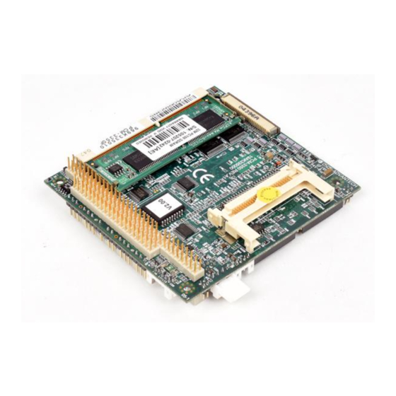
- Page 1 PCM-3350 Series NS Geode 586-Level PC/104 CPU Module with SVGA/LCD/ LAN Interface User's Manual...
-
Page 2: Copyright Notice
Copyright notice This document is copyrighted, 2001. All rights are reserved. The original manufacturer reserves the right to make improvements to the products described in this manual at any time without notice. No part of this manual may be reproduced, copied, translated or transmitted in any form or by any means without the prior written permission of the original manufacturer. -
Page 3: Packing List
Packing list Before you begin installing your card, please make sure that the following materials have been shipped: • 1 PCM-3350 All-in-one single board computer • CD-ROM or Disks for utility, drivers, and manuals (PDF format) • 1 2.5" IDE flat cable, 44-pin to 44-pin •... -
Page 4: Table Of Contents
Contents Chapter 1 General Information Introduction ............... 2 Features ................3 Specifications ..............4 1.3.1 Standard SBC functions ..........4 1.3.2 VGA function .............. 4 1.3.4 Ethernet function ............5 1.3.5 Solid state disk ............. 5 1.3.6 Mechanical and environmental ........5 Board dimensions ............ - Page 5 2.11 VGA connector (CN9) ........... 13 2.11.1 CRT display connector (CN9) ......... 13 2.12 Main power (+5 V / +12 V) connector (CN11) ..13 2.13 PS/2 keyboard/mouse connector (CN12) ....14 2.14 FDD connector (CN14) ..........14 2.14.1 Connecting the floppy drive ........14 2.15 CompactFlash™...
- Page 6 4.2.5 Power management setup ......... 33 4.2.6 PnP/PCI configuration ..........34 4.2.7 Integrated peripherals ..........35 4.2.8 Change password ............36 4.2.9 Save & exit setup ............37 4.2.10 Exit without saving ..........37 Chapter 5 PCI Bus Ethernet Interface Introduction ..............
- Page 7 C.6 PC/104 connector (CN6) ..........70 C.7 Parallel port connector (CN7) ........70 C.8 Backlight connector (CN8) ........... 71 C.9 VGA connector (CN9) ........... 71 C.10 Main power (+5 V) connector (CN11) ......72 C.11 PS/2 keyboard/mouse connector (CN12) ....72 C.12 FDD connector (CN14) ..........
- Page 8 Figures Figure 1-1: PCM-3350 dimensions ..............6 Figure 2-1: Locating connectors (component side) ........9 Figure 2-2: Locating connectors (solder side) ..........9 Figure 3-1: Contents of the PCM-3350 Series utility disk ......22 Figure 3-2: BIOS VGA setup screen .............. 23 Figure 4-1: BIOS setup program initial screen ..........
- Page 9 Tables Table 2-1: Connectors ...................... 8 Table 2-2: Serial port connections (COM1, COM2) ............11 Table 2-3: Serial port default settings ................12 Table B-1: PCM-3350 PC/104 connectors (CN6) ............64 Table C-1: Ethernet connector (CN1) ................66 Table C-2: LCD connector (CN2) ..................67 Table C-3: COM1 connector (CN3) ................
-
Page 11: Chapter 1 General Information
General Information This chapter gives background information on the PCM-3350. Sections include: • Introduction • Features • Specifications • Board dimensions... -
Page 12: Introduction
Flash chip holds the system BIOS and the VGA BIOS. This minimizes the chip usage and eases configuration. You can change the display BIOS simply by programming the Flash chip. If you need additional functions, the PCM-3350 has a PC/104 connec- tor for future upgrades. PCM-3350 User's Manual... -
Page 13: Features
1.2 Features • Ultra-compact size single board computer, smaller than a 3½" hard disk drive (96 mm x 90 mm) • Onboard NS Geode GX1 300MHz CPU • Up to 128 MB system memory, by way of SODIMM (SDRAM) • Onboard VGA/18-bit LCD interface •... -
Page 14: Specifications
• Display type: Supports CRT and TFT LCDs. Able to display both CRT and flat panel simultaneously • Flat-panel display mode: Panel resolution supports up to 1024 x 768 @ 18 bpp. Supports 18-bit TFT LCD panel PCM-3350 User's Manual... -
Page 15: Ethernet Function
• CRT display mode: Non-interlaced CRT monitor resolutions up to 1024 x 768 @ 24 bpp 1.3.4 Ethernet function • Chipset: Intel 82559 ER • Ethernet interface: PCI 10/100 Mbps Ethernet. IEEE 802.3 U protocol compatible • Connection: On-board 2 x 5 2.0 mm connector •... -
Page 16: Board Dimensions
1.4 Board dimensions Figure 1-1: PCM-3350 dimensions PCM-3350 User's Manual... -
Page 17: Chapter 2 Installation
Installation This chapter tells how to set up the PCM-3350 hardware. It includes instruc- tions on setting jumpers and connecting peripherals, switches and indicators. Make sure you read all the safety precautions before you begin the installation proce- dure. -
Page 18: Connectors
PC/104 connector Parallel port connector Backlight connector VGA connector CN11 Main power (+5 V) connector CN12 PS/2 keyboard/mouse connector CN14 FDD connector CN16 CompactFlash™ socket CN17 USB Connector CN18 COM2 RS422/485 connector Multifunction Jumper Slot 1 SODIMM socket PCM-3350 User's Manual... -
Page 19: Locating Connectors
2.2 Locating connectors Warning: Make sure you use the correct component side. Improper installation can cause serious damage to your hardware! Figure 2-1: Locating connectors (component side) Figure 2-2: Locating connectors (solder side) Chapter 2 Installation... -
Page 20: Safety Precautions
CMOS configuration. Refer to "BIOS Setting" in Chapter 4 for more information. 2.5 LCD display connector (CN2) CN2 is a 40-pin dual-in-line header and is used to connect an LCD display. PCM-3350 User's Manual... -
Page 21: Serial Ports
2.6 Serial ports (CN3: COM1; CN4: COM2/RS-232; CN18: COM2/RS-422/485) The PCA-3350F offers two serial ports: COM1 in RS-232 and COM2 (CN4: RS-232, CN18:RS-422/485). Refer to CMOS "Integrated Peripher- al" for RS-232, 422 or 485 settings. These ports let you connect to serial devices (mouse, printers, etc.) or a communication network. -
Page 22: Eide Hdd Connector (Cn5)
If you install two drives, you will need to set one as the master and one as the slave by using jumpers on the drives. If you install just one drive, set it as the master. 2.8 PC/104 connector (CN6) Refer to Appendix B in this manual. PCM-3350 User's Manual... -
Page 23: Parallel Port Connector (Cn7)
2.9 Parallel port connector (CN7) Normally, the parallel port is used to connect the card to a printer. The PCM-3350 includes a multi-mode (ECP/EPP/SPP) parallel port. It is accessed via CN7, a 26-pin flat-cable connector. You will need an adapter cable if you use a traditional DB-25 connec- tor. -
Page 24: Ps/2 Keyboard/Mouse Connector (Cn12)
Look for a number on the circuit board indicating pin number one. In addition, you should check if the connector on the floppy drive has an extra slot. If the slot is up, PCM-3350 User's Manual... -
Page 25: Compactflash™ Socket (Cn16)
pin number one should be on the right. Please refer to any documenta- tion that came with the drive for more information. If your cable needs to be custom made, you can find the pin assign- ments for the board's connector in Appendix C. 2.15 CompactFlash™... -
Page 26: Multifunction Jumpers (Mj1)
MJ1-D 12-16 IR connect Pin14: Receive Pin15: GND Pin16: Transmit Watchdog Pin 18-19: IRQ11 MJ1-E 18-20 connect Pin 19-20: reset 2.17.1 Auxilary power connector (MJ1-A) Supplies secondary power to peripherals that require -5 V and -12 V. PCM-3350 User's Manual... -
Page 27: Fan Connector (Mj1-B)
2.17.2 Fan connector (MJ1-B) The PCM-3350 is equipped with a low power dissipation GX1 CPU. With only a heat sink, the PCM-3350 will operate normally at tempera- tures up to 60° C. At temperatures above 60° C, a fan is recommended. A CPU fan power supply connector is provided (+5 V input) in addition to the CPU power supply. -
Page 28: So Dimm Socket (Slot1)
The SODIMM should not move around in its socket. Important: Only use standard form SODIMM memory modules (as shown in the diagram below). Standardized dimensions ensure a proper fit. Check with your memory supplier about the SODIMM modules you will use. PCM-3350 User's Manual... - Page 29 Chapter 2 Installation...
- Page 30 PCM-3350 User's Manual...
-
Page 31: Chapter 3 Software Configuration
Software Configuration This chapter details the software configu- ration information. It shows you how to configure the card to match your applica- tion requirements. Award system BIOS is covered in Chapter 4. Sections include: • LCD display configuration • Connections for two standard LCDs... -
Page 32: Introduction
It is also capable of driving color panel displays with resolutions of 1024 x 768 in 18 bpp. The LCD type is configured completely via the software utility, so you do not have to set any jumpers. Configure the LCD type as follows: PCM-3350 User's Manual... -
Page 33: Figure 3-2: Bios Vga Setup Screen
1. Apply power to the PCM-3350 Series with a color TFT display attached. This is the default setting for the PCM-3350 series. Make sure that the AWDFLASH.EXE and *.BIN files are located in the working drive. Note: Make sure that you do not run AWDFLASH.EXE while your system is operating in EMM386 mode. -
Page 34: Connections For Two Standard Lcds
3.4.1 Connections for Toshiba LTM10C042(640 x 480 TFT color LCD) Table 3-1: Connections for Toshiba LTM10C042 LTM10C042 PCM-3350 Series CN 2 Name Name SHFCLK PD12 PD13 PD14 PD15 PD16 PD17 PD10 PD11 ENAB +5 V +5 V PCM-3350 User's Manual... -
Page 35: Connections For Toshiba Ltm12C275A (800 X 600 Tft Color Lcd)
3.4.2 Connections for Toshiba LTM12C275A (800 x 600 TFT color LCD) Table 3-2: Connections for Toshiba LTM12C275A LTM12C275A PCM-3350 Series CN 2 Name Name NCLK SHFCLK PD12 PD13 PD14 PD15 PD16 PD17 PD10 PD11 ENAB M/DE +5 V +5 V Chapter 3 Software Configuration... - Page 36 PCM-3350 User's Manual...
-
Page 37: Chapter 4 Award Bios Setup
Award BIOS Setup This chapter describes how to set BIOS configuration data. -
Page 38: System Test And Initialization
The PCM-3350 CMOS memory has an integral lithium battery backup. The battery backup should last ten years in normal service, but when it finally runs down, you will need to replace the complete unit. PCM-3350 User's Manual... -
Page 39: Award Bios Setup
Award BIOS setup Award’s BIOS ROM has a built-in Setup program that allows users to modify the basic system configuration. This type of information is stored in battery-backed CMOS RAM so that it retains the Setup information when the power is turned off. 4.2.1 Entering setup Power on the computer and press <Del>... -
Page 40: Standard Cmos Setup
This standard Setup Menu allows users to configure system components such as date, time, hard disk drive, floppy drive and display. Once a field is highlighted, on-line help information is displayed in the left bottom of the Menu screen. Figure 4-2: CMOS setup screen PCM-3350 User's Manual... -
Page 41: Bios Features Setup
4.2.3 BIOS features setup By choosing the BIOS FEATURES SETUP option from the INITIAL SETUP SCREEN menu, the screen below is displayed. This sample screen contains the manufacturer’s default values for the PCM- 3350. Figure 4-3: BIOS features setup Chapter 4 Award BIOS Setup... -
Page 42: Chipset Features Setup
4.2.4 Chipset features setup By choosing the CHIPSET FEATURES SETUP option from the INITIAL SETUP SCREEN menu, the screen below is displayed. This sample screen contains the manufacturer’s default values for the PCM-3350. Figure 4-4: Chipset PCM-3350 User's Manual... -
Page 43: Power Management Setup
4.2.5 Power management setup By choosing the POWER MANAGEMENT SETUP option from the INITIAL SETUP SCREEN menu, the screen below is displayed. This sample screen contains the manufacturer’s default values for the PCM-3350. Figure 4-5: Power management setup Chapter 4 Award BIOS Setup... -
Page 44: Pnp/Pci Configuration
4.2.6 PnP/PCI configuration By choosing the PnP/PCI CONFIGURATION option from the Initial Setup Screen menu, the screen below is displayed. This sample screen contains the manufacturer’s default values for the PCM- 3350. Figure 4-6: PnP/PCI configuration PCM-3350 User's Manual... -
Page 45: Integrated Peripherals
4.2.7 Integrated peripherals By choosing the INTEGRATED PERIPHERALS option from the INITIAL SETUP SCREEN menu, the screen below is displayed. This sample screen contains the manufacturer’s default values for the PCM-3350. The PANEL TYPE by default supports a 18-bit 640 x 480 TFT LCD panel display. -
Page 46: Change Password
(user-defined), you can change the password stored in the CMOS. The password can be at most eight (8) characters long. Remember - to enable this feature, you must first select either Setup or System in the BIOS FEATURES SETUP. PCM-3350 User's Manual... -
Page 47: Save & Exit Setup
4.2.9 Save & exit setup If you select this option and press <Enter>, the values entered in the setup utilities will be recorded in the chipset’s CMOS memory. The microprocessor will check this every time you turn your system on and compare this to what it finds as it checks the system. - Page 48 PCM-3350 User's Manual...
-
Page 49: Chapter 5 Pci Bus Ethernet Interface
PCI Bus Ethernet Interface This chapter provides information on Ethernet configuration. • Introduction • Installation of Ethernet driver for Windows 98/NT/2000 • Further information... -
Page 50: Introduction
MS-DOS or Windows. Note: The windows illustrations in this chapter are exam- ples only. You must follow the flow chart instructions and pay attention to the instructions which then appear on your screen. PCM-3350 User's Manual... -
Page 51: Installation For Windows 98/2000
5.2.2 Installation for Windows 98/2000 1. a. Select "Start", "Settings". "Control Panel". b. Double click "Network". 2. a. Click "Add" and prepare to install network functions. Chapter 5 PCI Bus Ethernet Interface... - Page 52 3. a. Select the "Adapter" item to add the Ethernet card. 4. a. Click "Have Disk" to install the driver 5. a. Insert the CD into the D:\drive b. Fill in "D:\PC104\3350\LAN\82559ER\W9x&w2k" c. Click "OK" D:\PC104\3350\LAN\82559ER\W9x&w2k PCM-3350 User's Manual...
- Page 53 6. a. Choose the "82559ER" item. b. Click "OK". 7. a. Make sure the configurations of relative items are set correctly. b. Click "OK" to reboot. Note: The correct path for Windows NT is: "D:\PC104\3350\LAN\82559ER\WinNT" Chapter 5 PCI Bus Ethernet Interface...
-
Page 54: Further Information
5.3 Further information Realtek website: www.Realtek.com EMAC website:www.emacinc.com PCM-3350 User's Manual... -
Page 55: Chapter 6 Svga Setup
SVGA Setup • Introduction • Installation of SVGA driver for Win- dows 95/98/NT... -
Page 56: Introduction
Note 3: When you are using a CRT display, please make sure that your flat panel resolution settings (in the BIOS setup) are the same as your VGA resolution settings (in Windows). Otherwise your display may behave strangely. PCM-3350 User's Manual... -
Page 57: Installation For Cyrix Mediagx Certified Drivers For Windows 95/98. Insert The Disk Into The Cd-Rom Drive
6.2.1 Installation for Cyrix MediaGX Certified drivers for Windows 95/98. Insert the disk into the CD-ROM drive. 1. Select "Start" then "Run". 2. Type the correct path for the driver (like the example below) "D:\PC104\3350\VGA\Win9xc_40" 3. Click "OK" D:\PC104\3350\VGA\Win9xc_40 Chapter 6 SVGA Setup... - Page 58 2. Click "Finish" to continue. 3. Click "Next" to proceed to the next step. Click "Yes" after you read the license agreement. PCM-3350 User's Manual...
- Page 59 4. Follow the instructions which appear on the screen. 5. Insert the Win95/ 98 CD-ROM into the CD-ROM drive. Type the correct path for the Win9 x source file. Chapter 6 SVGA Setup...
- Page 60 6. Choose "Yes", then click "Finish" to restart the computer. PCM-3350 User's Manual...
-
Page 61: Installation For Windows Nt
6.2.2 Installation for Windows NT 1. a. Select "Start", "Settings" then "Control Panel" to get to the screen below. b. Double click on the "Display" icon. 2. a. Choose the "Settings" selection. b. Click the "Display Type" button. Chapter 6 SVGA Setup... - Page 62 3.Press the "Change..." button. 4. Click on the "Have Disk..." button PCM-3350 User's Manual...
- Page 63 5. a. Insert the disk into the CD-ROM drive. b. Type "D:\PC104\3350\VGA\WINNT\VGA.110\" c. Press "OK". D:\PC104\3350\VGA\WINNT\VGA.110\ 6. a. Select the highlighted item. b. Press "OK". Chapter 6 SVGA Setup...
- Page 64 7. Press "Yes" to proceed. 8. Press "OK" to reboot. PCM-3350 User's Manual...
- Page 65 9. a. Repeat Step 1 in this manual, select the "Settings" label. b. Adjust the resolution and color. c. Click "Test" to see the results. d. Click "OK" to save the settings. Chapter 6 SVGA Setup...
-
Page 66: Further Information
Further information For further information about the PCI/SVGA installation in your PCM-3350, including driver updates, troubleshooting guides and FAQ lists, visit the following web resources: Cyrix web site: www.national.com EMAC web site: www.emacinc.com PCM-3350 User's Manual... -
Page 67: Appendix A Programming The Watchdog Timer
Programming the Watchdog Timer The PCM-3350 is equipped with a watchdog timer that resets the CPU or generates an interrupt if processing comes to a standstill for any reason. This feature ensures system reliability in industrial standalone or unmanned environments. -
Page 68: Programming The Watchdog Timer
You must make your program so that it writes 1 to I/O port 443 at an interval shorter than the timer's preset interval. The timer's intervals have a tolerance of ± 30%, so you should program an instruction that will refresh the timer about every second. PCM-3350 User's Manual... -
Page 69: Appendix A Programming The Watchdog Timer
The following example shows how you might program the watchdog timer in BASIC: Watchdog timer example program X=Out &H443,1 REM Enable and refresh the watchdog GOSUB 1000 REM Task #1, takes 1 second to complete X=Out &H443,1 REM Refresh the watchdog GOSUB 2000 REM Task #2, takes 1 second to complete... - Page 70 PCM-3350 User's Manual...
-
Page 71: Appendix B Installing Pc/104 Modules
Installing PC/104 Modules This appendix gives instructions for installing PC/104 modules. -
Page 72: Installing Pc/104 Modules
(Refer to the diagram on the following page.) 4. Mount the PC/104 module onto the CPU card by pressing the module firmly but carefully onto the mounting connectors. 5. Secure the PC/104 module onto the CPU card using the four mounting spacers and screws. PCM-3350 User's Manual... -
Page 73: Figure B-1: Pc/104 Module Mounting Diagram
PC/104 Mounting Support Male Female PC/104 module PCM-3346 Figure B-1: PC/104 module mounting diagram 82.5 95.9 90.8 90.8 85.1 90.2 Figure B-2: PC/104 module dimensions (mm) (±0.1) Appendix B Installing PC/104 Modules... -
Page 74: Table B-1: Pcm-3350 Pc/104 Connectors (Cn6)
SA10 IRQ7 — — IRQ6 — — IRQ5 — — IRQ4 — — IRQ3 — — DACK2* — — — — BALE — — +5 V — — — — — — — — * low active PCM-3350 User's Manual... -
Page 75: Appendix C Pin Assignments
Pin Assignments This appendix contains information of a detailed or specialized nature. It includes: • Ethernet connector • LCD connector • COM1 connector • COM2 connector • EIDE HDD connector • PC/104 connector • Parallel port connector • Backlight connector •... -
Page 76: Ethernet Connector (Cn1)
C.1 Ethernet connector (CN1) Table C-1: Ethernet connector (CN1) Signal Signal Vcc (+5 V) ACTLED- LILED- PCM-3350 User's Manual... -
Page 77: Lcd Connector (Cn2)
C.2 LCD connector (CN2) Table C-2: LCD connector (CN2) Signal Signal VDDSAFE +5 V VDDSAFE +5 V VDDSAFE +3.3 V VDDSAFE +3.3 V SHIFT CLOCK FLM (FIRST LINE MARKER) M (DISPLAY ENABLE) LP (LATCH PULSE) ENABKL ENAVEE Note: The model number of the CN2 socket is DF13A-40DP-1.25V (Hirose Electric Co., Ltd.) Appendix C Pin Assignments... -
Page 78: Com1 Connector (Cn3)
C.3 COM1 connector (CN3) Table C-3: COM1 connector (CN3) Signal Signal RLSD C.4 COM2 connector (CN4) Table C-4: COM2 connector (CN4) Signal Signal RLSD PCM-3350 User's Manual... -
Page 79: Eide Hard Drive Connector (Cn5)
C.5 EIDE hard drive connector (CN5) Table C-5: EIDE hard drive connector (CN5) Signal Signal *RESET *IOW *IOR IOCHRDY *DACK SA 0 *HDCS1 *HDCS3 * low active Appendix C Pin Assignments... -
Page 80: Pc/104 Connector (Cn6)
C.6 PC/104 connector (CN6) For details on PC/104 connectors, please refer to Appendix B. C.7 Parallel port connector (CN7) Table C-7: Parallel port connector (CN7) Signal Signal *STROBE ERROR INIT SLIN ACKNOWLEDGE BUSY PE (PAPER EMPTY) SLCT * low active PCM-3350 User's Manual... -
Page 81: Backlight Connector (Cn8)
C.8 Backlight connector (CN8) Table C-8: Backlight connector (CN8) Signal +12 V BACKLIGHT ENABLE C.9 VGA connector (CN9) Table C-9: VGA connector (CN11) Signal Signal RED_OUT VCC_VGA GREEN_OUT BLUE-OUT D2C_DATA D2C_CLOCK Appendix C Pin Assignments... -
Page 82: Main Power (+5 V) Connector (Cn11)
Table C-10: Main power (+5 V) connector (CN11) Signal +12 V Vcc (+5) C.11 PS/2 keyboard/mouse connector (CN12) Table C-11: PS/2 keyboard/mouse connector (CN12) Signal PS/2 KB CLOCK PS/2 KB DATA PS/2 MOUSE CLOCK PS/2 MOUSE DATA PCM-3350 User's Manual... -
Page 83: Fdd Connector (Cn14)
C.12 FDD connector (CN14) Table C-12: FDD connector (CN14) Signal Vcc (5 V) INDEX Vcc (5 V) DRIVE SELECT 0 Vcc (5 V) DISK CHANGE NC (READY) NC (HD OUT) MOTOR ON DIRECTION SELECT NC (1.6 MB IN) STEP WRITE DATA WRITE GATE TRACK 00 WRITE PROTECT... - Page 84 C.13 USB connector (CN17) Table C-13: USB connector Signal Signal USBVCC (5 V) 2 USB VCC (5 V) DATA 0- DATA 1- DATA 0+ DATA 1+...
-
Page 85: Compactflash™ Socket (Cn16)
C.13CompactFlash™ socket (CN16) Table C-13: CompactFlash™ socket (CN16) Signal Signal *CS0 *ATA SEL +5 V *IOCS16 *CD2 *CD1 *CS1 *VS1 *IORD *IOWR INTRQ +5 V *CSEL *VS2 *RESER IORDY *INPACK *REG *DASP *PDIAG * low active PCM-3350 User's Manual... -
Page 86: Figure C-1: Compactflash™ Socket
Figure C-1: CompactFlash™ socket Appendix C Pin Assignments... -
Page 87: Com2 Connector For 422/485 (Cn18)
RXD - 485 RXD + 485 TXD + 485 TXD - 485 C.15 Multifunction Jumpter (MJ1) Table C-15: MJ1-A, -5 V, -12 V input Signal -5 V -12 V Table C-16: MJ1-B, fan connector Signal +5 V +12 V PCM-3350 User's Manual... -
Page 88: Table C-18: Mj1-D, Ir Connector
Table C-17: MJ1-C, reset button Signal *system reset Table C-18: MJ1-D, IR connector Signal +5 V Receive Transmit Table C-19: MJ1-E, watchdog jumper Signal *IRQ11 Watchdog signal *system reset *low active Appendix C Pin Assignments... - Page 89 PCM-3350 User's Manual...
-
Page 90: Appendix D System Assignments
System Assignments • System I/O ports • DMA channel assignments • Interrupt assignments • 1st MB memory map... -
Page 91: Table D-1: System I/O Ports
Parallel printer port 1 (LPT1) 380-38F SDLC, bisynchronous 2 3A0-3AF Bisynchronous 1 3B0-3BF Monochrome display and printer adapter (LPT1) 3C0-3CF Reserved 3D0-3DF Color/graphics monitor adapter 3F0-3F7 Diskette controller 3F8-3FF Serial port 1 Watchdog timer ** default setting PCM-3350 User's Manual... -
Page 92: Dma Channel Assignments
D.2 DMA channel assignments Table D-2: DMA channel assignments Channel Function Available Available Floppy disk (8-bit transfer) Parallel** Cascade for DMA controller 1 Available Available Available ** Parallel port DMA default setting: DMA 3 Parallel port DMA select: DMA 1, 3 Appendix D System Assignments... -
Page 93: Interrupt Assignments
IRQ 10 Available IRQ 11 Reserved for watchdog timer IRQ 12 PS/2 mouse IRQ 13 INT from co-processor IRQ 14 Preliminary IDE IRQ 15 Secondary IDE for CompactFlash USB and Ethernet IRQ is automatically set by the system PCM-3350 User's Manual... -
Page 94: 1St Mb Memory Map
D.4 1st MB memory map Table D-4: 1st MB memory map Addr. range (Hex) Device F000h - FFFFh System ROM E000 - EFFF Unused CC00 - DFFF available C800 - CBFF Ethernet ROM* C000h - C7FFh VGA BIOS B800h - BFFFh CGA/EGA/VGA text B000h - B7FFh Reserved for graphic mode usage...
Need help?
Do you have a question about the PCM-3350 Series and is the answer not in the manual?
Questions and answers